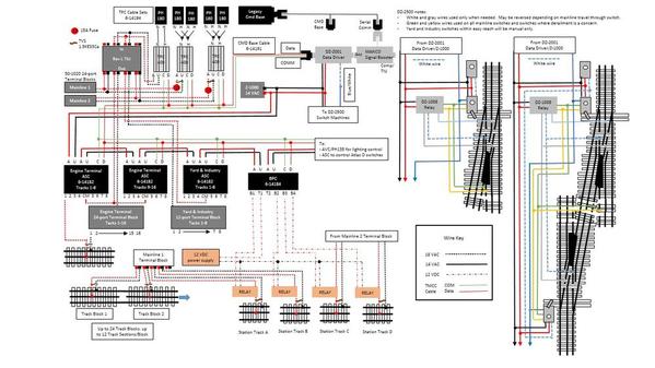
Below is the electrical diagram for my layout. The purpose of the diagram is to help me keep track of all the wires, but I thought I'd post it for others to review and let me know if I missed anything or made any errors. This plan is for the first stage of my layout, which includes two mainline tracks, several engine terminal tracks to park engines, and a five track yard plus a couple of industries. Layout control will be through TMCC except for a few switches within easy reach; these will be manual. The TIU is for MTH engine control only. Most switches will be controlled by DZ-2500 switch machines, but there will be a few Atlas O switches controlled by an ASC. While I will run mostly command control, the plan allows conventional control through TPCs. The plan allows 15 amps to the mainline tracks to run my multi-engine, 10+ car passenger trains (K-line cars with power consuming Streamlighting). However, the second PH180 attached to each TPC will not be turned on unless needed. To get the 15 amps to the mainlines, the TIU is set up in passive mode for those tracks. Also because of the 15 amps, I will use relays controlled by a BPC I have to turn on/off 4 blocks on the mainlines.
I currently own all the components in the diagram, so I don't plan to buy anything else (except the relays, I'm still looking for those). Any comments on my plan would be appreciated. Thanks.
Ron


