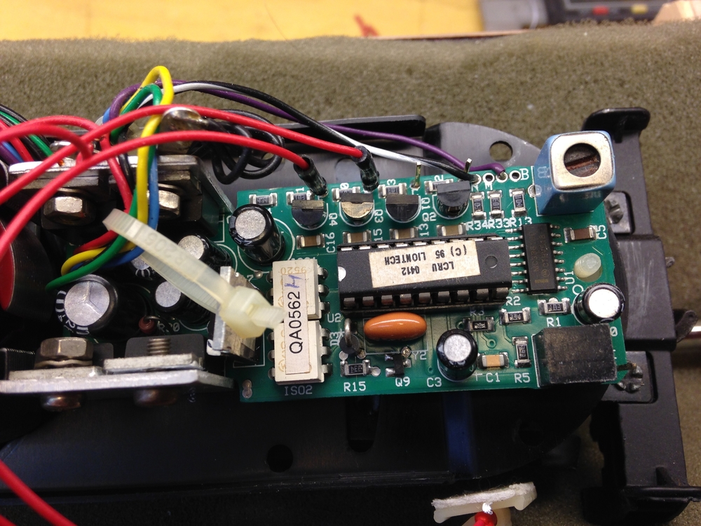
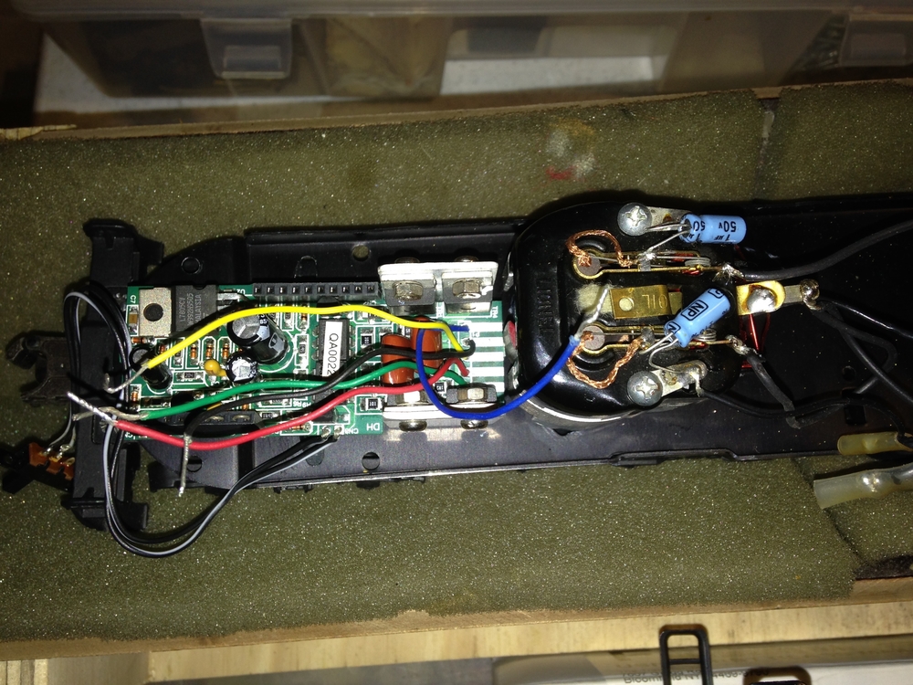
Need Info on an electronic e-unit for Pullmor motors, p/n 610-8689-126. The PWB appears to be 6108918-126. Got it off da Bay and haven’t found any source of specific info regarding the two 10-pin header sockets. I found a few mentions of this unit on OGR and other train related places, but nobody talks about the purpose of those two sockets. This is clearly a Lionel unit, but is has whiffs and overtones of a Protosound 1 board, what with the sockets and all. I have the basic wiring sorted out, motor, power and lockout switch, and the unit is fully functional when it comes to running and reversing a motor.


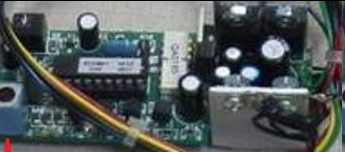
One of the two 10-pin sockets has two jumpers in place – purpose? Some of the pins on the opposite socket have pcb traces running to them, but no jumpers are present, so they may serve some function? I was really hoping to get some directional lighting off this board, but don’t know if that was part of the design.
The board is used on a Dash 8-40B, #4002, p/n 6-18211, and on Dash 8-40B, #4004, p/n 6-18218 and on an SD-60 #5500 6-18216.
Any help you can offer with regard to the sockets and/or directional lighting would be much appreciated!
George