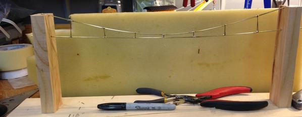
I've started building some catenary sections for my future empire.  I'm using 1/16"  and .032" brass rod.  The distance between support posts is about 17" +/-.  The 1/16" rod comes in 36" lengths, so one rod is enough for one complete section, suspension and contact wires.  

The last layout that had catenary was about 30 years ago.  I built that one in place using the 1/16" rod alone.  It worked well but the carriers were a bit over sized.  Plus, since I don't have a layout yet, building the catenary in place would be somewhat difficult.....LOL   

In those days I soldered it all with a tiny gas torch.  It was nothing more than a gas capsule, similar to CO2 capsules, housed in an open frame.  There was a thumb screw on the top that punctured the tip of the capsule.  I was alot younger then too.  I have since upgraded to a butane refillable torch.

In that layout of long ago the catenary was live which allowed me more possibilities for running more trains on the same track.

Anyway, here are some photos of what I am doing.  I built a jig to make the task a bit simpler.  For some reason, the contact wire appears to be drooping.  It has something to do with the photo, as it is actually straight.

IMG_4582IMG_4583IMG_4584

Attachments

Images (3)
  • IMG_4582
  • IMG_4583
  • IMG_4584
Last edited by Former Member
Original Post

Replies sorted oldest to newest

Excellent work, Dan.  I look forward to your progress, as some day I'll be fabricating my own catenary.

The perceived bend in the trolley wire is only an optical illusion caused by the bent telegraph wire. 

I wonder if some sort of a jig that lays on a flat surface would serve you better, although I see the advantage in having access to both sides while soldering.  My thinking is that a simple jig of nails into a 1X4 board would ensure consistently identical replicas.   Wrapping the end wires once around each nail then tacking it with solder will produce a nice loop for attachment to the next section.  In this way you could either solder or bolt the sections together, depending on your preference, or your need for adaptation. 

I'm leaning towards 1/2" extruded aluminum U for uprights and simple bar for the crossbars.   I have the materials to experiment with, it's finding the time.

Bruce

Add Reply

Post
The Track Planning and Layout Design Forum is sponsored by

AN OGR FORUM CHARTER SPONSOR

OGR Publishing, Inc., 1310 Eastside Centre Ct, Suite 6, Mountain Home, AR 72653
800-980-OGRR (6477)
www.ogaugerr.com

×
×
×
×
Link copied to your clipboard.
×
×