Congratulations Trainman!! I always run trains before I get to far along in wiring, just to make sure nothing has to be changed
Clem
|


|
Congratulations Trainman!! I always run trains before I get to far along in wiring, just to make sure nothing has to be changed
Clem
Thanks Clem. I've really appreciated your input to get this far. I've been advised to leave that loop as long as possible so I can keep running trains to kill the boredom of building. I also want to bring the engines out one at a time and charge their batteries.
Work was very short today since my client has just moved to a new location and didn't need a consultant hanging around. I just checked in to see if things were going as planned and left. That gave me some serious time to continue working on the control panel.
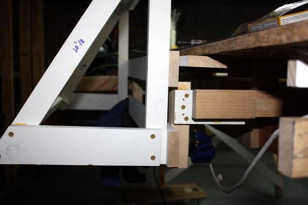
Here's the panel frame clamped onto the braces that are in turn assembled to the joists under the layout.
The top rail will be held with SPAX screws, but the lower section will be held to the braces with carriage bolts. All the braces are screwed AND glued with Titebond.
Here's the suspension structure. It's 1 X 3s with a 2 X 2 hanger. There will be two points of suspension.
The back, bottom and sides will be sheathed with 1/4" ply to which all the circuitry will be fastened.
Here's an artist rendering of the ply installed
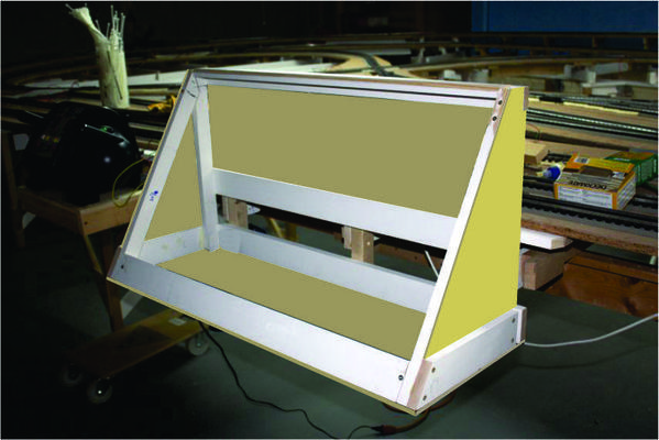
and another artist impression of the final job with the panel in place. Aren't graphics programs cool?
I hope someone can help me understand how to power all the indicator lights with LEDs. I understand they're DC and that polarity is important and that you must limit the current to each one. But is there a way to feed all of them so that you don't need the resistor at each LED. I've got 74 of them on this panel. There's a green and red at each block and there are 37 blocks. I think I'll pose this question on the electrical forum too.
Like yesterday, I got done with work early and finished up the control panel installation. So here's the finished unit. Compares very closely to yesterday's "artist's impression".
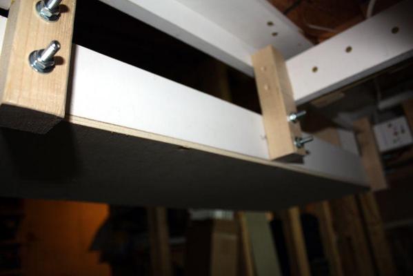
Here's a shot from the back showing the robust bolting that holding the lower section to the layout structure. The upper part is secured with five long screws into the white 2 X 3 that's secured to the layout edge. I can pick myself up from the scooter so it's pretty strong.
The last thing I did was drill the three holes on top to secure the plexi to the frame. I use a oval-head screws with dress-washers. I modified a small drill for plastics work as before, and the drilled the holes. I was rushing! I forgot to reduce the DeWalt's speed to the slowest and it drilled the holes very fast. So fast that on the 3rd hole the drill buried itself in the wood structure beneath the panel and enlarged it too big. When I put the screw in the hole, there was no wood left for any threads to grab.
After dinner I went down and filled the hole with J-B Weld and tomorrow I'll re-drill with a pilot-sized drill and thread the screw in again. I also took some of the epoxy and reinforced the one rail at the swing gate that was a bit shaky. J-B Weld is some powerful stuff. It's a steel-powder filled epoxy that is drillable after it cures. It cures very slowly (24 hours), but it's worth the wait.
Tomorrow I will fit the piano hinge that goes across the entire bottom of the plexi and will secure the lower portion. I haven't decided if I'm going to mount all the hardware and wiring with the panel on or off. I see advantages in doing it in either way.
I have another opportunity which is to mount the MTH DCS TIUs vertically on the back wall of the box. This would make running wires from the TIUs to the block toggles. I would have to drill vent holes in the top of the box's back so there would be convective air flow from bottom to top. I know that the DCS book says to minimize the length of wire runs from TIUs to track, but my toggles all reside here in the panel. I would rather have the TIUs here and accessible than buried under the layout tied to a leg or something. Since I'm also planning on adding Lionel Legacy, the power brick would have to go outside of the box, but it doesn't have the multitude of wires emanating from it.
I would like to paint the unit, but I haven't decided on what color. I was going to paint the fascia boards a hunter green, but that seems to dark for the panel box. I was also thinking about a UP Armour Yellow or gray, or maybe Pennsy Tuscan Red since both are roads that I feature.
I'm still researching the LED lighting question. I can get the LEDs themselves for very little money (80 of them for like 10 dollars), but it's the power supply and the current limiting resistors that may cost more money. I also have to find out when running a panel full of them if you need a resistor at EACH LED or can a resistor that feeds the bank of them. Help is always needed!
Trainman, I dont know where your shopping, but generally resistors, in 100-200 quantity shouldn't be more than 5 cents each for 1/4 watt units. You can get LED's with the resitor build in to operate on 12Vdc but they are pricey. you can also get LEDS with the resistor and a nice mounting benzel (not sure if thats the right term here) but they are upwards of 1.00 each. Do some online research, and dont fall victim to Radio Shacks over priced stuff, you'll be lucky if they have 5 in stock any way
Ryan
check these out, 1.75 each, but really nice
http://www.allelectronics.com/...or-Assemblies/1.html
You have come this far with the layout, and the control pannel will be a attention grabber, so do it right, I dont think 160.00 for indicators that look nice is too much., just my opinion. I think i will be using these on my control pannel
they also offer this guide on there site
Trainman.... was sitting here reading your last post about the plunger and all and thought wonder if a simple infra red detector a simpler approach to gate opened or closed?
I'm no electronics guru so forgive me if i inject something more involved or?
I have enjoyed your build so far thanks for sharing it with us.
I do have to comment from the photo of control panel it appears high and looks to hide the layout some? had a crazy thought of if it could be raised and lowered below layout height when using command control via DCS or? or do you intend to use the control panel to change the track switches?
have fun with your two Grandson's and train layout work and better yet running some trains with them.
$oo
Good morning Trainman
Taking a break from spiking rails,what a boring job, don't know how those 2 rail guys do it. Do you think maybe a magnet might be used for your relays?
Clem
I'm glad everyone is enjoying the build. It's fun to write about it and it lets me learn at the same time.
Infrared might be a way to go. I'm stuck in a mechanical paradigm...
I could use an MTH infrared track detector and reflect it off a target on the door. You'd still need a relay to switch the main power, but the IR could probably switch the signal lights all by itself.
Panel Height:
The panel is going to control all the switches. I'm not planning on using an AIU (at least not now) although "scene" feature would a useful function to line up a half dozen switches when doing some of the moves. I ran the trains from a panel like this before and found it to be fun.
So the height was a compromise between "not block too much view" and "reaching the switch controllers at the panel's bottom". Also, I wanted the kids to be able to reach everything, but also have it convenient for me. It's in front of a section of all straight track without any switches so there's nothing much to see at that point. The panel's too wide to lay horizontal without really cutting into the aisleway. Actually that was a section where due to my panel cutting errors, had very little free space beyond the track. It was so close that it would have been difficult to ballast the track there. By adding the 2 X 3 mounting rail, and the the panel frame, it really closes this danger spot off. I will fill that area and landscape it up to the panel. The location is also an area where I have the most floor space around the panel, but also have a view of most of the yard tracks.
Clem, were you thinking about "Hall Effect" switches when you mentioned magnets? If not, you'll need to explain more. I already have the micro switch, the relay and the time circuit, so I don't want to spend too much more money on this.
Trainman~ I'm not sure. I thought there was a sensor that would trip a relay when a magnetic field was close.
Yes, there are magnet switches which are mechanical and then there are Hall Effect switches that are solid-state devices that change state in presence of a magnetic field. I'll let you all see the microswitch plan when it's finished. It should work okay. I want to trip the circuit the minute the latch is no longer latched rather than waiting for the gate to actually start moving. That way if anyone leaves the latch unhooked while the gate looks closed the indicator will be red and the trains won't go through this section.
Here's my attempt at the schematic. I'm using an RC bellcrank to transfer the vertical motion of the plunger to horizontal motion to the microswitch. I'm doing this only because it will allow more flexibility in aligning all the parts. There are extra contacts in the relay so I'll be using most of them.
I'm using the normally open (NO) contacts for the track power. This way when the microswitch closes it energizes the relay coil and closes those contacts energizing the swing-gate blocks. Meanwhile the other set of NO contacts will energize the green signals at the dwarf block at the gate and the panel indicator green. When the gate latch is lifted sufficiently to release the microswitch, it de-energizes the relay coil and the contacts open breaking the circuit to the track blocks. It also opens the green indicator contacts turning the green off and the normally closed contacts make energizing the red signal indicating the gate is not locked and track power is off. This will be the first time I've ever designed and installed a relay circuit. I know some of the guys on the forum use them for all sorts of things. As I get more comfortable I may do that also.
Please critique. For example, I'm not sure if using the NO contacts for the track power is the best approach being that the relay coil is continuously energized in this mode. If I used the NC set, the coil would only energize when the gate opens (also by selecting the NC contacts on the microswitch which passes current when the switch is in the non-activated position). I've been told that the relay doesn't mind being energized all the time; they're designed to do this.
This graphic was produced on Microsoft Visio which is a great program for knocking stuff out quickly. I've been using it since version 1 in the early 90s.
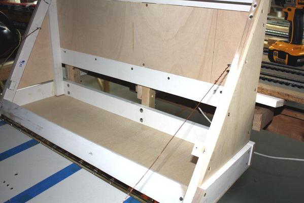
I was supposed to work today, but #1 grandson was off from school so I took the day off too. I finished up the Panel construction with the additional of the piano hinge at the bottom and some picture wire to support the panel face when it's open.
My grandson, meanwhile, was unpacking more locomotives and again, right out of a four-year hibernation, they all ran superbly. He got the coal turbine running which he claims is one of his 5 favorites. We even smoked the place up a bit with the engine smoke generators (2) all fired up. It was an engine that my wife selected at the train store in 2000. She saw it sitting on the shelf and thought it looked cool and said I should buy it. When your spouse says you should buy a huge locomotive, the only word you should then say is, "Yes!"
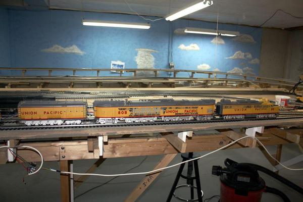
In case anyone ever gets the idea to run this engine on anything smaller than O88, take a look at the overhang coming around this corner. You have to be very careful what scenery and signaling is put trackside.
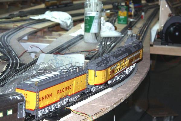
We also ran my 3rd Rail Pennsy T-1 Demonstrator, which is one of my favorite engines. Most of the engines are my favorites since I bought all of them.
Grandson then suggested that I paint the new control in Union Pacific and Pennsy colors. So I took a nice Pennsy Bobber caboose and a UP caboose to The Home Depot and had them match the colors. They were able to get a good read off the UP caboose because it had nice smooth sides, but the bobber gave them some trouble but they found a very similar shade in their computer already.
I painted the yellow first. Tomorrow, I'll mask the yellow and paint some the unpainted external areas Tuscan red. Should look nice.
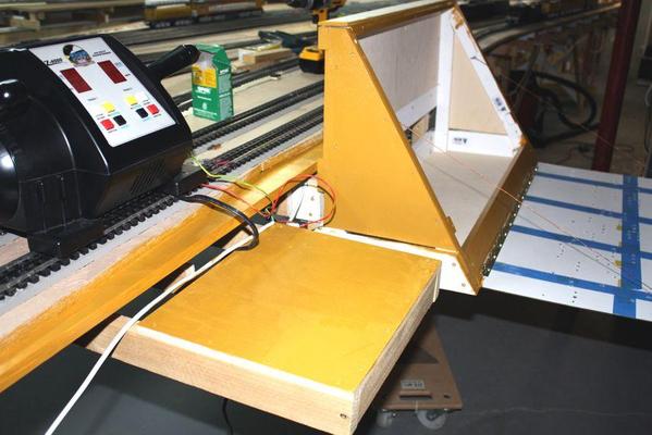
While out, I stopped at Radio Shack and ordered 10, 8 position barrier strips and buss bars to make the input section from the DCS TIU. I've got the wiring figured out. I'm going to be able to select whether I'm driving from the fixed voltage output from the TIU from the left channel on the Z4000 or from the right variable channel. This will be done with all those DPDT toggles on the panel. In this way any section of the layout can either be digital or analog by operators selection. This doesn't negate being able to use the Z4K DCS feature, but lets me run the railroad with cab control before I buy the digital equipment. I will have two terminal connections in the digital run... to the barrier strips in the control panel, and where the track pigtails join the run below the platform. I will directly splice the lead from the output of the toggles all the way to the track so I won't be using another barrier strip. When originally wired, all these leads went through a barrier strip so the panel could be removed and shipped. This layout's not going anywhere.
And I bit the bullet and ordered 250 feet each of 14 and 16 gauge twisted pair from OGRR. I will use that avionics wire to power all the switches and other power users on the layout, but not the track. It's only 20 gauge. It's also shielded with a very-difficult-to-remove insulation that I didn't want to mess with any more than I have to. I may need a bit more than this, but for the very short runs near the panel I can use other wire that I have.
I still have to drill the cooling holes on the box. Forgot to that before I painted it. Oh well...
So the LEDs are ordered along with a power supply, the terminal strips are ordered as is the wiring. I already have all the DPDT switches I need. All that's left to buy is the digital equipment.
BTW: What is the current production version of MTH's DCS? I keep seeing them on eBay and I'm a little squeamish about buying one on-line. There's good train stores in town that should get my business.
Put some final touches on the control cabinet. It's painted Tuscan Red and UP Armour Yellow. I cobbled together some logos from both roads and decorated the sides with them. Later this week, when the supplies arrive, I will start doing some actual wiring. I'm getting bored running trains only around the outer loop.
I pulled the 3rd Rail, J1-a out of it's long slumber. Oiled it up and it ran perfectly. I love this engine and like how it looks elevated at eye level. It's old technology, now 16 years old, but it works nicely. I suppose someday I'll upgrade its electronics so it will have more bells and whistles — after all, it's a steam engine... it already has SOME bells and whistles. I have the drawbar set on the closest hole. With my curves I think it could even be a bit closer.
Trainman,
You can buy LEDs that have the necessary resister built-in. You must specify the voltage. Please see the attached datasheet that I downloaded from Jameco.
Jan
Now you tell me... Unfortunately, that train has left the station...no pun intended. Since I already have a brace of red and green 5mm LEDs, I will slog on. I also realized that the resistor doesn't have to be physically connected to the LED, just somewhere in series with the LED, power and ground. So I can put the LEDs in the board run leads down to the terminal strips and install the resistors there...whatever's easiest. The less stuff physically hanging on the Plexiglass, the better I like it.
I also realized in yesterday's operating session that I better build that ^%#(@) interlock on the swing gate. I turned on the H-8 and had it running down the front tangent only to look down and see that the GATE WAS OPEN! Since I was closer to the gate than the throttle, I walked very quickly, got to the gate when the engine was 2 feet away and got it closed in a nick of time. TOO CLOSE...WAY TOO CLOSE! It was real "Casey Jones" moment.
This was not the first time that the gate was open when the trains were moving. I have the interlock scheme all figured out and should build it as soon as I can. Having a $1,700 brass engine hit the concrete is more than I could handle.
Sorry about being a day late.
You can also get RYG LEDs and R or G ones too. The latter have three leads. I'm not totally certain on how the RYG work but I believe they work based on the polarity - pos to neg gives red, neg to pos gives green, and AC gives yellow.
Jan
I built the mechanical parts of the interlock. I went to the Hobby Shop and got some RC components to go with the microswitch that I bought at Radio Shack. It seemed like the best way was to mount the components on brass and then attach them to the layout. In these pictures, the wood block is not yet fastened down. I need to grind the trigger stem flat since the latch can ride off it and not engage the power.
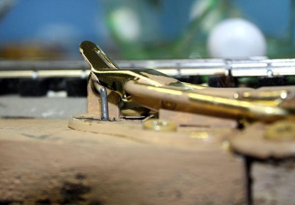
I had to play with the spring location so it pulled up properly without binding. There's also a plastic sleeve in the layout structure to provide a running surface for the trigger. This is also a model aircraft component.
Here's the "closed" state:
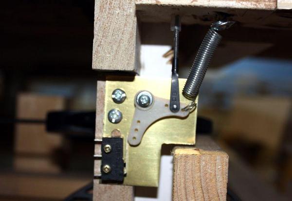
When the latch is raised, the relay will cut the power to all the blocks butting up to the swing gate and switch the indicator LEDs on the panel from green to red.
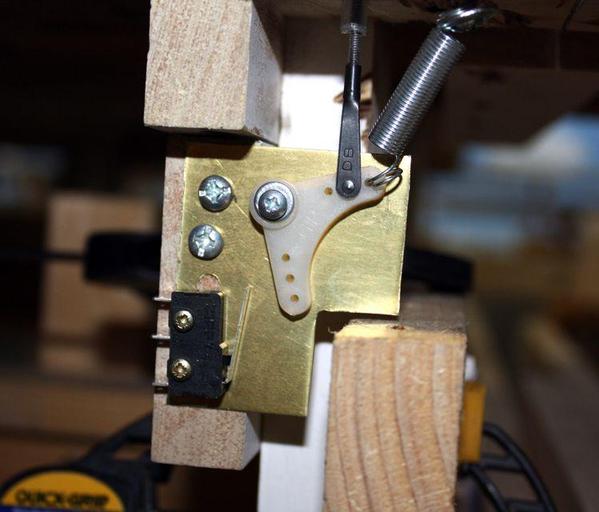
When closed, a timing circuit will hold the power off for a period of time to give the operator(s) the opportunity to make sure everything is okay before energizing the circuit. I'm going to add a stop on the trigger shaft so it doesn't rise too high. This will also help keep the latch from overriding the trigger.
Just as a memory jogger; here's the design drawing I made.
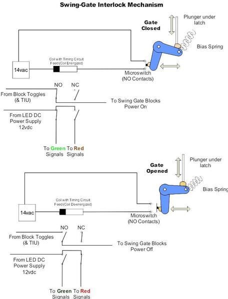
I will wire it up next session (maybe tonight...definitely tomorrow).
Started to officially wire the layout today. Did a little this morning while grandson #2 was building a space alien with modeling clay, then got involved in building the Motorized Marble Madness Machine by K'nex. It's a monster project which gets built and torn down every couple of years. The kids love it. But, I did get back down to the shop this evening and got a little more done.
I fastened all the barrier strips to the cabinet floor based on this schematic I drew yesterday.
Barrier strips alternate being 'hot' and 'common' with the throttles (green and red) down each side. I have enough hot terminals for one wire at each since some will come off the interlock strip on the right side, but some of the commons returning from the field will be doubled up.
Here's the barrier strips screwed down to the base. I doubled the ply in the base since I was using a 3/4" screw and it would have poked through the bottom. Doubling made this problem go away.
The barrier strips all have jumper bars so they each have 16 screw terminals all with the same voltage. The center strip in the right end with the 6 terminals has a split jumper forming two 3-terminal strips. This is where the interlock blocks will get power. It's interrupted by the relay circuit. The interlock leads are fastened in this view.
Here's the power wiring in place. I went around the layout and replaced some of the "American Style" barrier strips with "Euro-style" ones, and of course I ended up reversing the polarity.
When or if I go with MTH's DCS digital control, I will substitute the power feeds from the red throttle with the feeds from the DCS. The rest of the wiring will remain exactly as it is since I'm already using "home run" wiring with heavier gauge twisted-pair as they recommend. If I didn't intend on ever using DCS, I wouldn't have been as particular with the barrier strips and would have used a ground loop for the common returns instead of bringing every common back to the control panel. But this gives me flexibility and I can add the control system whenever I want.
I turned on the transformer to make sure that all was okay. The idea here is to install one circuit, test and verify it and then move onto the next one. So I turned it on, the engine on the track made some funny sounds and didn't move, the other channel on the transformer was showing voltage and current loads, and then the overload light lit. I pulled on the leads from the "Red" channel which was NOT going to the track and the short still existed. So I realized it must be something out of the panel. I checked each of the places where I exchanged the strips and there it was.
I put the blue wire into the hole with the brown wire on the other side and vice versa. Dead short! Exchanged the wire locations and there were no more shorts. I'm not colored blind, but screwups like this make me wonder...
I have more meetings tomorrow, but I may get some more time in the shop. I have to buy larger lead ends for the 14 gauge wire I bought for the long runs. The ferrules and spade lugs I have are not large enough.
Access to this requires an OGR Forum Supporting Membership
