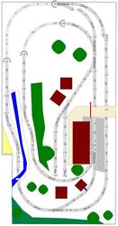
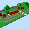
I finally had some time this weekend to get started on the new layout. It is an L-shaped 10x12 with 2 main lines. The objective here was to create a modular layout that could be put up a few times a year and otherwise stored in the garage.


I built the benchwork out of 1x4s in 4 modules (roughly 43x66 each). The legs can be removed and the modules are held together by carriage bolts and wing nuts. (Below is a picture of a test run to see how the track plan fits)

layout_062412


I have to say that seeing the plans come to life surprised me in the actual size. It looked more compact in the plans (see attached). Storing it in the garage will take up even more space once scenery is added. I am working on a system that will consume the least amount of space yet provide enough protection for the tracks.


Since the picture was taken, I have now installed fiberboard to put a flat surface on the benchwork. The next decision is to whether to add a layer of building foam (homasote) or start the terraforming with mountains and plaster right way.


Also I noticed that the connection and disconnection of Fastrack can be pretty forecful/jerky. If anybody has suggestions on how to best connect fastrack pieces between modules without endangering scenery, I would be interested.

Attachments

Images (2)
  • layout_062412
  • track10
Original Post

Replies sorted oldest to newest

Why is it necessary to physically connect the Fastrack[forceful/jerky] at the Module joints? I am not familiar with Fastrack and may be missing something.

Can you not just have them electrically connected via separate wire runs to each Module's track with track simply butted together with just a minicule narrow gap where it physically crosses the joint between units? The train won't know that the rails are not connected. 

It is possible to remove the pins that connect fastrack, thus allowing you to have two pieces of track that butt together but are not physically connected.  Pry-up and Loosen the metal tabs undeneath each  rail to remove the pins.


Another idea is to have a piece of track span the gap.  Then cut the track to align with the joint. 


As mentioned, you then have to eletrically connect the track segments with wires and connectors.

Last weekend I went through the dry-fitting process to test out the concept from the CAD drawings. I reworked the design to make it smaller (no more L-shape) and more compact. Running the tracks all the way to the edges would leave only minimal space for scenery or a safety zone for accidents.
Sometimes less is more and the reduced scope will help with the usability and portability.

The new design is attached as well as a picture of the test tracks.
track12
I will fasten the fasttrack to the foam on each module with drywall screws and then cut off the plastic tabs for the connecting pieces. With the modules being connected to each other, it should provide sufficient connection. Since I was running into some electrical issues with test-running, I will make sure to have sufficient wiring to each track block. The different modules will be connected via plugs.

Attachments

Images (3)
  • track12_3d: 3D rendering of the revised track plan
  • track12: Revised track plan
  • dry_fit: Dryfitting the new track plan

After a few more weekends I was able to get the layout moving again. I did a lot of electrical work to get it set up for conventional block control. A control panel with two cabs is now in place and operational. The plan had to be adjusted a few times to make it work better. Since the basic track is now functioning, I am having my son test run the layout before we start with the more advanced (permanent) scenery.


It is still a modular layout that can be taken apart and stored. The electrical connections from module to module and via plugs and work really well. I do have some dead spots on some of the older Fastrack pieces. though, that I am trying to identify and fix. In addition I getting the operating accessories installed as well.

There is no good spot for the cattle loading platform and I will need to leave it out. You don't want it close to a regularly used track since the loading platform needs to be very tight to fit and that can make passing trains get caught.


photo 1


Close up of the control panel. I plan to update it with some LED's indicating the blocks and potentially the switch direction. The current paper map will also be updated with a plexi-class cover to give it a more finished look. Otherwise it is full workable and well situated.

photo 2


Testing in progress with more items in play. We notices also that the yard was too far in the middle of the layout and moved it in by 10 inches. That makes the operating easier. The tunnel is just the wood frame. Next step will be to install the tunnel portals and build up the hillside. I plan to have a removable hill-top above.

The incline from Woodlands Scenics was a great investment. It really made the transitions easy. 3% incline allows for some variation and is not too much for the trains to handle.

photo 3

photo 4


No California layout is complete without palm trees.

photo 5

Attachments

Images (5)
  • photo 1
  • photo 2
  • photo 3
  • photo 4
  • photo 5
Post
The Track Planning and Layout Design Forum is sponsored by

AN OGR FORUM CHARTER SPONSOR

OGR Publishing, Inc., 1310 Eastside Centre Ct, Suite 6, Mountain Home, AR 72653
800-980-OGRR (6477)
www.ogaugerr.com

×
×
×
×
Link copied to your clipboard.
×
×