@DoubleDAZ posted:

John,

My thought is that it’s better to wire a single long run with larger gauge wire to a terminal strip so you can use smaller gauge wire for the shorter runs from the strip to the power feeds. I have no idea what length defines a long run though. 🤣

That's a good idea with a layout this size. Depending on how many trains will be running at once it may be necessary to extend two TIU channels to each zone marked on the layout for load balancing. Something to consider.

When it comes to wire I tend to follow what the car guys have out there for information, specifically a wire ampacity chart over distance. Amps are amps. So, following Dave's suggestion the wire out to the remote strips can be 14 ga out to about 20 feet, 12 from 20 feet on. All of the drops to the terminal strips under 5 or 6 feet can be 18 ga.

If you want to turn those whisker/siding tracks on and off with DCS you will need to study what effects this will have on the watch dog interaction between the TIU and DCS engines. In short, watch dog signals are generated by the TIU when track power is first applied to a TIU channel. If the engines don't see this watch dog they will come up in conventional mode. There are several long threads on this and @gunrunnerjohn found an elegant solution.

@DoubleDAZ posted:

John,

Here's a diagram to generate some conversation regarding how best to wire the layout. It is by no means the best way or the only way, just something for discussion.

As you can probably tell, I put the control panel (gray) on the yard side of things. I then ran wires to the yard and to the left/top sides where terminal strips would be. The Blue, Green and Yellow sections would be further broken into power blocks and I'd block each spur so you could store an engine on each and turn off the power. You'd also want to block each whisker track. You'd then divide the Blue, Green and Yellow tracks into blocks being sure to limit the size of each to conform to recommended DCS lengths and number of joints. Remember, these are just for power feeds, so 2 smaller blocks are better than 1 longer one.

John 2021-01-12b Daz wiring

Ok here is a question on panel placement. The majority of track in the green area is yard and roundhouse. I would anticipate most of those being powered off for train storage. With the control panel being in that area, it will have the lowest draw which would be able to handle having the longest run from panel. Why have the panel there and not across the isle? Is it for yard switching? I am sure I do not have the working knowledge of this situation.

All comments are needed and welcome

Unless you are planning a control panel of "olden" days with a track diagram and toggle switches protruding from it at given locations, many of the panels now seen on these pages are just locations where power and wiring start, with the biggest concerns being large enough to handle power supplies, heat and access for repairs or modifications.  So if yours is to be of the newer style, the best location would be on either side of your widest aisle.  Then, you would put your toggle switches (or whatever you decide to control your powered on-off sidings) right on the railroad fascia near the siding location.

On the other hand, if you choose the "olden" style panel, Dave's location is probably best because you will probably spend a lot more time building and disassembling trains in the yard and moving engines in/out of the roundhouse than anything else.  The current versions of "olden" style panels generally conceal the power supplies and wiring under an angled panel top where the user sits next to it.

Chuck

Dan, that makes much more sense, thanks for clarifying.

John, there’s nothing magical about the placement of the panel, I just put it somewhere. If it were me, I’d probably put it on the left so power runs to the top and bottom terminal strips would be similar in length. Like Chuck mentioned, a lot depends on how you define “panel”. For me, it’s simply your transformer and TIU. “Old style” design would then suggest a “control” panel near the yard. It would be a diagram of the yard with toggle switches for power and turnout activation. There’d be another one across the aisle for the turnouts in that section. However, modern designs generally locate power and turnout controls along the facia or on the layout because a lot of control is now done from the remote, not by manually pushing buttons or toggling switches. Where you locate the transformer/TIU generally depends on if you plan to run conventional where you need access to the transformer handle(s). If not, then they can be tucked out of the way. A lot of folks put then on a cart or panel that can be pulled out for maintenance, etc.

Last edited by DoubleDAZ
@PRR1950 posted:

Unless you are planning a control panel of "olden" days with a track diagram and toggle switches protruding from it at given locations, many of the panels now seen on these pages are just locations where power and wiring start, with the biggest concerns being large enough to handle power supplies, heat and access for repairs or modifications.  So if yours is to be of the newer style, the best location would be on either side of your widest aisle.  Then, you would put your toggle switches (or whatever you decide to control your powered on-off sidings) right on the railroad fascia near the siding location.

On the other hand, if you choose the "olden" style panel, Dave's location is probably best because you will probably spend a lot more time building and disassembling trains in the yard and moving engines in/out of the roundhouse than anything else.  The current versions of "olden" style panels generally conceal the power supplies and wiring under an angled panel top where the user sits next to it.

Chuck

Great Info and I hope to have a newer style panel and definitely provide air flow, access and  power for that panel. This leads me to be swapping to the other side of the aisle and keeping the higher power demands at the shortest distance that is practical.  Hope this will be a good choice? If anyone has other suggestions please post them and those posts will be appreciated.

Thanks John

@DoubleDAZ posted:

Dan, that makes much more sense, thanks for clarifying.

If it were me, I’d probably put it on the left so power runs to the top and bottom terminal strips would be similar in length. Like Chuck mentioned, a lot depends on how you define “panel”. For me, it’s simply your transformer and TIU.

However, modern designs generally locate power and turnout controls along the facia or on the layout because a lot of control is now done from the remote, not by manually pushing buttons or toggling switches. Where you locate the transformer/TIU generally depends on if you plan to run conventional where you need access to the transformer handle(s). If not, then they can be tucked out of the way. A lot of folks put then on a cart or panel that can be pulled out for maintenance, etc.

Hi Dave, I am not sure what you are saying with power runs to the top and bottom terminal strips being similar in length ?  And when you say left side, is that where you placed it on the drawing you posted?

And I was anticipating having transformer, TIU and two AIU's in this configuration. With circuit breakers, fuses and an arduino micro for special functions.

Thanks John

Last edited by Aegis21

John,

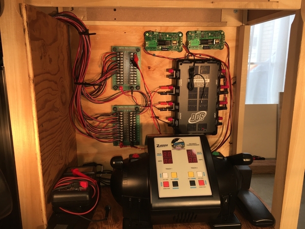
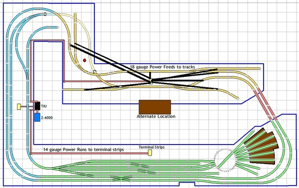
Here's a new photo. You can place the control panel with the Z-4000, TIU and AIUs pretty much anywhere. However, if you place it where the Brown rectangle is across from the yard AND you include the terminal strips like Mark did, you'll have to run a large number of power feeds all the way around the layout to get power to the yard. Looking at Marks photo, it appears he ran about 22 feeds and used larger gauge wires from the terminal strips to the tracks than from the TIU to the terminal strips.

My suggestion is simply that you place your terminal strips closer to the track power blocks. If you leave the control panel where the Brown rectangle is, you need a single long feed to yard terminal strip, a medium length feed to the bridge terminal strip and a short feed to the town terminal strip. If you locate it where I have it though, you have a shorter run to the yard strip, a similar length run to the town strip and short run to the bridge strip. I don't the gauges wires Mark used, but if it matters, you'd use less of the larger gauge wire and more of the smaller gauge wire.

I added Red power feeds to the terminal strips and Black feeds to the tracks in the town. You'd have similar feeds from the other 2 terminal strips to the yard and bridge tracks.

I don't think either configuration is wrong, I just don't like having to trace long feeds when building or troubleshooting. Most wiring designs I've seen place terminal strips closer to the action, so to speak. If you unfold the design with the Green tracks on the left, the Blue in the middle and the Yellow on the right, you end up with all the terminal strips where the Brown rectangle is on one end of a long run.

Just food for thought, nothing more.
John 2021-01-12b Daz wiring

Attachments

Images (1)
  • John 2021-01-12b Daz wiring

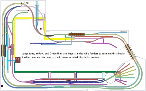
Ok here is a first try at power distribution for this layout. Following MTH guidelines (at least I think I did?) and everyone's input, here is the result for now. Three separate power districts, feed by 14ga. stranded wire from three tiu outputs which will have over current protection and indicator lamps. Then tracks are feed by 18ga stranded wire from terminal strips to tracks with a method of switching power (yet to be determined) to isolate those blocks from each other for both engine control (shutting off engines not in use in round house or spurs) and fault isolation. I tried my best to color code things to help make sense of this potential rats nest. Labeling the wire runs maybe something along TIU-PD1 to PD1-T1-1,2  So this would be connection between the first TIU output to power district 1 terminal strip 1, terminals 1 and 2 Making odd always black return and even numbers red hot side.

Everyone, please let me know of better power distribution methods, labeling etc. Always a better way to skin a cat!

Thanks in advanceJohn 2021-07-20_Block_Wiring

Attachments

John, I'm so sorry I didn't get back to you!!!  Thank you for reminding me!!  I inadvertently deleted the email reminder on my phone, and didn't think of it.

First off, PT is going well.  I just finished 6 weeks of it already.  I am getting some more flexibility and strength, and there is less back pain.  In fact, very little back pain except when I get up in the morning for a half hour or so.  My sciatic nerve is a different story, though I think I am seeing progress.  I had a couple nights with less pain from it.  The therapist told me I won't see a steady progress, but there will be ups and downs.  I am taking a challenge tomorrow in that I am going to go to the Monroeville Greenburg show.  I did okay a couple weeks ago driving to see my mum at the hospital which was a 45-minute drive each way.  She got a pacemaker, and is back at her personal care home.  I'm going to not take Rt 8 and Turnpike, but go an alternate route that doesn't take much longer, but I can stop whenever I need to.  The trip to Monroeville takes about an hour and 15 minutes.  The therapist wants a report on how I do when I go back in on Monday.

On to your wiring diagram.  Following along, you did the same thing I did, except I only have one major terminal since my layout is smaller.  Looking at all the drops, they all make sense, unless I missed one or two.  However, if you missed any on the diagram, you will pick it up when you are wiring.  That happened to me; I missed one and am glad I bought 24-terminal blocks and not 12-terminal blocks.  I would have been one short on the sidings.

Have you made any more progress on the benchwork or had any thoughts on the backdrop?

Hi Mark,

Glad to hear you are doing better and by the looks of your wiring on your layout, you must be doing really well to do such an outstanding job combing those wires into perfect positions. I am finally getting back to building the benchwork on my setup after months of it being idle. I did get some time to tinker with controlling layout block power and block occupancy detection and turnouts, using wireless ESP8266 system on chip (SOC) the idea is to eliminate wiring each block sensor, turnout, and block power control back to either control center or toggle switches. I have the basics working and will wait until some track is laid before final verification of viability and usefulness is vetted. I'll start to post some picks as I restart bench work progress.

Thanks for your help and inspiration to get back to the layout.

John

John, thank you for the compliments!  I’m glad you are getting some time to get back to your layout.  Your plan for block occupancy and turnouts sounds great!  Even with my setup, after I drew a schematic, I sat on my stool in front of the AIU panel and mocked up a circuit with the AIU, DZ1000, and push button, and alligator clip jumpers.  I’ll look forward to seeing what you are doing!

Hi Mark, General gist is to use AIU to set an input to the "home unit" esp32 which in turn will wirelessly send the command to a "slave" esp8266 relay board swiching a turnout or enabling power to a block depending on what you want to do. Also have an esp8266 detect block occupancy by using one of two inputs with an isolated outside rail as a switch detecting occupancy and second input detecting block power. This one will send status back to "home" esp32 and light up led's for visual and maybe an arduino mega controlling signals and the like. Obviously still in planning stage, however I did write the code and verified it  working to at least control the relays and status leds. So back to bench work! I am getting to the last stretch of base bench work as I have a straight wall then into an alcove, back wall straight then right angle back to be almost even with starting bench work on opposite wall . The last straight run is not completed yet. I'll post some pics later when I get a chance. Oldest daughter is moving out this week and I will be busy for sure with her move to Pittsburg area. Thank goodness it is not too far!

Add Reply

Post
The Track Planning and Layout Design Forum is sponsored by

AN OGR FORUM CHARTER SPONSOR

OGR Publishing, Inc., 1310 Eastside Centre Ct, Suite 6, Mountain Home, AR 72653
800-980-OGRR (6477)
www.ogaugerr.com

×
×
×
×
Link copied to your clipboard.
×
×