@Aegis21 posted:

Mark, totally agree on needing to change around TT and recheck spacing. This is a first draft so to speak and a starting point.  I have started another topic only dealing with benchwork. not sure if that was a good idea to split things up or not... As for drawing it on scarm, well the track is on the floor and the supports are in the air! LOL

Yes, that is the kind of thing I struggles with as well!! 

Again, John Armstrong does a great job on explaining the variations and relationship of  TT and RH.  His work is well worth a read to better understand the why and wherefore of so much of what we do.

As far as "L" girder construction vs flat deck I do not see it as a either / or but the need to use which ever format that best serve the situation.

Another consideration is the flex nature of the building material to be selected.   I have built layouts with 5.5 mm Meranti and they have survived for decades.  I have seen layouts built with 3/4" CDX which turned into potato chips within one year.  1/2" Pine decked layouts which became shallow hammocks.

Here is an inverted example of a 5.5 mm waffle bottom module:

Walk in add on waffle module bottom & top view 006

So it is not just the thickness but more so the quality of the material and the techniques used in assembly.

One of the more recent products available to us today is Advantech by Huber industries.  I have used this successfully for over a decade without incident.

I mention this because one of my Millhouse TTs is sitting in an Advantech hole on two partial fingers with out any additional support elements since 2010.

Here is the triple bunk bed style module upon which one of my Millhouse TTs are mounted.  Nothing fancy, overbuild or girdered.  Just a pair of fingers.  TT is on the top tier.

3 level module 002

The only support is a pair of short recessed fingers, one of which is vaguely seen half way down the right  frame edge.   The sandwich of Advantech and Homasote is very sturdy.  I thought it to be about time to apply a fascia so blocks are mounted ready to go.

IMG_9712

A side suggestion for mounting these Millhouse TTs.  I found that 1/4" threaded T-nuts recessed into the Advantech deck then covered with Homasote is a real clean firm method to pick up the tabs plus it makes it real easy to use a socket and extension or a nut driver to fine tune the bridge track  to the radial rail heads as opposed to multiple nuts and wrenches with a drop through screw.

Attachments

Images (3)
  • Walk in add on waffle module bottom &  top view 006
  • 3 level module 002
  • IMG_9712
Last edited by Tom Tee
@DoubleDAZ posted:

John, here's a version with the everything raised 1" above the bench work. The way to do it is to hide the bench work, then select everything else and use the Height Shift tool in the Toolbox to increase the height to 43" (or whatever you want).

test2

Dave, This is wh you are the scarm wizzard! How do I get the green bbaseboard up to that height, or do I put in other polgons and raise those up for terrain?

John, to get the baseboard up to the height you have to draw a transparent polygon around the baseboard and select "snap to grid". However, as you can see, that covers up your bench work. So, it's best no to select "snap to grid" and select a color for the polygon. In this case I chose yellow and placed it on the Decking layer. As you'll see when you open the file, the decking covers almost everything and prevents you from selecting a lot of objects while making changes, so you have to turn off that layer.

test1

test2

Attachments

Images (2)
  • test1
  • test2
Files (1)
@DoubleDAZ posted:

John, to get the baseboard up to the height you have to draw a transparent polygon around the baseboard and select "snap to grid". However, as you can see, that covers up your bench work. So, it's best no to select "snap to grid" and select a color for the polygon. In this case I chose yellow and placed it on the Decking layer. As you'll see when you open the file, the decking covers almost everything and prevents you from selecting a lot of objects while making changes, so you have to turn off that layer.

test1

test2

No Doubt you are the Wizard of Scarm!

@DoubleDAZ posted:

John, to get the baseboard up to the height you have to draw a transparent polygon around the baseboard and select "snap to grid". However, as you can see, that covers up your bench work. So, it's best no to select "snap to grid" and select a color for the polygon. In this case I chose yellow and placed it on the Decking layer. As you'll see when you open the file, the decking covers almost everything and prevents you from selecting a lot of objects while making changes, so you have to turn off that layer.

Hi Dave,  I see that the turntable is a millhouse 28" 36 position 10 degree The round house footprint, is that based off of a 3 stall Korber RH? And is it positioned up against the TT or set back some distance for clearances? Since I have neither TT or RH, it would be great to keep options open. Ross is the other TT I have "looked" at and Altoona, Brennen, and Korber make nice roundhouses. All with pros and cons.

Thanks John

John, thanks to your question it looks like the Atlas RH mated to the 28" Millhouse TT was indeed placed too close to the TT, though it wasn't touching. Whoever created the RH object in SCARM added a floor that extended past the front. You could see it wasn't touching when viewed in 3D. However, it was still too close, so I moved it further away and reconfigured the floor so it didn't extend past the RH.

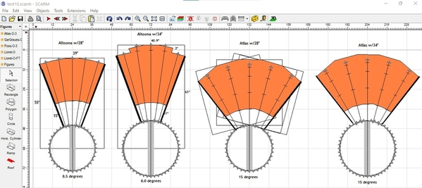
I've spent much of the day fiddling with specs, drawings and photos for both brands. Here's what I've been able to put together for the Atlas on the top and the Korber on the bottom. Atlas says their RH is supposed to fit inside a 40x40" box butted against the TT, while Korber says their RH is supposed to fit in a 30.0x28.5" box and be 16.2" from the TT, so that's what I've done, you can see the outlines.

The top left is Atlas RH with 28" TT.
Top right is Atlas RH with 34" TT.
Bottom left is Korber 3-stall with 34" TT.
Bottom right is Korber 4-stall with 34" TT.

From what I can tell the Korber model someone created in SCARM does not match the outline, so I had to create a footprint for both the 3-stall and 4-stall models. What's missing is the Big Boy expansion kit that Korber makes. Dealing with manufacturer specs and photos of their roundhouses is a very frustrating exercise, they all provide specs differently. The bigger frustration is that people want to see models of the roundhouse and not just the footprint even though all they need is the footprint to see whether it will fit or not. I'm finding that footprints are accurate, the models folks have created for SCARM may not be.

Anyway, as you can see in the top photos, the box touches the TT and the RH fits inside. The 34" configuration needs to be moved up 3" and to the right 12.4" to fit the space and will increase the depth of the bench work in that area. You can see where the TT would be located in the bottom photos.

You can also see how the Korber model doesn't fit inside the box properly, so it needs a little more space than expected. Korber did provide enough specs for me to create the footprint diagrams and place them 16.2" from the TT. AFAIK, that should be correct. Unfortunately, Atlas was not so forthcoming. Here again I don't know if the RH is accurate. Atlas says the track from the TT to the rear wall of the RH is 37.25". If I place the RH in the photos so the track touches the 37" track, it will touch the TT instead of the rear wall. I don't think Atlas means the "rear wall" literally and I think I have it in the right position and it's about 3" from the TT. Trouble is their photo shows it a lot further from the TT than 3", so I'm lost. If you look at the model, the front and back corners touch the sides of the box, so I think it's accurate. The whiskers are 15° just like Atlas says and appear to be properly aligned inside the RH. I hope you can see how difficult it is for me to say with certainty that things will fit. I'm fairly confident with the footprints, just not the SCARM models.

test4

Attachments

Images (1)
  • test4

Hi Dave, Sounds like I opened landlord's boxes. You certainly dig into things for sure. I also was on a similar garden path today, although it sounds like you got some answers. Everything you said makes sense and is technically sound. Not sure if putting in a 34 or 33"  TT is worth the extra space and added reach hassles. Alll comments welcome. I don't anticipate getting a Big Boy loco within the next 50 years. Btw I'm going to be 68 next month. I know "never say never"  At this point my thoughts are for more stalls for RH 5 max and 28" or 27" TT

Can see how uncertain things are for fitting. Foot prints that are vague or specs that differ from RH mfg. To TT mtg do not lend themselves to instill confidence in anyone. The box concept for RH is shared by Altoona RH at this point I think they measured box from center of TT. Like 60" x  35" I'll do some more research tomorrow . One other note, RH mtg did not mention TT angle of at least I did not see it.  I did not look at Atlas RH which you said was 15° Now that is not only accurate info but useful too!

Again many thanks  john

John, no worries, just a little frustrating that all manufacturers don’t define their footprint the same way, at least not on their websites. Altoona seems to be the best. They measure from the center of the TT and appear to have 2 models; 55” with 26” walls and 60” with 32” walls. Both have capability for 3” extensions to extend the walls to 29” and 35”.

They say the 55” is for use with 26-30” TTs and show the 1” difference in distance from TT to front wall between 28” and 30” TTs. This suggests another 1” for the 26” making the distances 14, 15 and 16”. They don’t say it can’t be used with larger TTs, but I suppose the assumption is that if you need a 34” TT, then you need a longer RH.

Then they show the 60” with the 34” TT, but say nothing about smaller TTs, so I don’t know for sure if you simply add 1” for a 32” TT or if it can even be used with smaller TTs, though I see no technical reason it can’t.

To muddy things more, they go on to show a 15-stall model with a 34” TT that appears to use the 55” version because it mentions the 26” wall and 60” to the rear wall. However, they don’t show how far is it from the TT. So they make you guess by subtracting the 26” wall and the radius of the TT (17”) from the 60” to end up with the RH 17” from the TT. How hard would it be to include those dimensions?

Now, by turning off the track outline and turning on the center rail in SCARM, I’ve been somewhat successful creating roundhouses as long as they provide a footprint box. It takes a lot of trial and error because they never provide the degree of offset. Korber does the best job of explaining what happens if you try to place the RH closer to the TT, but Brennan carries this further by discussing the use of curved leads to the RH. Unfortunately, they don’t mention engine clearance, or at least I didn’t see it. The key is extending the straight track outside enough so the engine will clear regardless of the curve, but they don’t even hint at that, so it becomes trial and error. I suppose most folks who buy this stuff contact the manufacturers to get the information and they have large layouts. I get frustrated because I can’t definitively tell someone if something will fit or not. I’m pretty sure I understand things, but so far no one has validated that understanding other than Bob from Altoona when I was asking all these questions for anther layout.

Here’s what I’ve gone through with Altoona and Atlas 5-stall RHs and 28”/34” TTs. The Altoona took the longest because of all the trial and errors to figure out the angles. The Atlas took about 10 minutes because the provided the angle. Once I figured out the angled, it was just a matter of rotating the RH that many degrees and adding the whisker tracks. To get the walls it’s just half the angle and drawing a line to the edge of the box. The Atlas was a bit more involved, but it was just a matter of rotating the box 15°, then 7.5° for the sides. However, I don’t know the length of the sides, so I just guessed at about 28”. The main thing is the size of the box and you can see how much wider the Atlas is compared to the Altoona. The Atlas doesn’t have the Big Boy extension, so it appears shorter than the Altoona, but it won’t be. It’s obvious the Atlas takes up the most room, especially width.

Not sure what this all means, but maybe it’ll help you figure out what the next step is.

F3D8872C-F03F-452A-8359-A1C986CBB856

Attachments

Images (1)
  • F3D8872C-F03F-452A-8359-A1C986CBB856

Hi Dave,

It is beginning to look like a 27" or 28" TT and a three or four stall RH, With all the input and considering finances, I am leaning Towards a 3 or 4 stall Korber RH with Ross 27" TT    Just looking at the space reality and $  Nothing is set in stone until there is a good indication on the best physical fit for both. I think this RH on scarm is close to Korber RH. This was the best I could do with sifting through the pile of data. LOL

And of course you have been a huge help with everything. ThanksJohn 2020-11-30 daz

Attachments

Images (1)
  • John 2020-11-30 daz
Files (1)
Last edited by Aegis21

Hi John,

Not to belabor this issue, but if you're leaning toward the Korber and Ross combo, I feel it's useful to get as close as possible to the real thing., So, I redid the footprint for Korber 304 model RH with 4 stalls and mated it to the Ross 27" TT. While looking for photos of the actual model, I found 2 threads related to the RH and included the links just FYI. I don't know why I didn't think to check with Mike CT, I consider him an expert on roundhouses and turntables, but I didn't know he's built at least 2 of these kits. I'm going to ask him to take a look at this thread, at least this last post.
https://ogrforum.ogaugerr.com/...ll-korber-roundhouse
https://ogrforum.ogaugerr.com/...s-and-build-problems

Anyway, the photos I found lead me to think I found out why the Korber model I have for SCARM doesn't look right. It's because I believe it includes the Big Boy extension. The 4-stall RH is supposed to fit in a 30.7"x38" box and the one in SCARM doesn't. It also has to be 16.2" from the TT and it's not. So, I replaced it with what I think is close to the real model (lite gray) and added 4 extensions (dark gray). Now, the extensions aren't needed for your use, though you could add just 1 on the 1st (lowest) whisker track where a large engine could go straight into the RH without having to be turned on the TT. That's one way to future-proofing a change of heart at some point and you decide to purchase a large engine.

I also redid the whisker tracks outside the RH to make sure the curves were O-72 or greater.


test

Attachments

Images (1)
  • test
Files (1)
@DoubleDAZ posted:

Hi John,

Not to belabor this issue, but if you're leaning toward the Korber and Ross combo, I feel it's useful to get as close as possible to the real thing., So, I redid the footprint for Korber 304 model RH with 4 stalls and mated it to the Ross 27" TT. While looking for photos of the actual model, I found 2 threads related to the RH and included the links just FYI. I don't know why I didn't think to check with Mike CT, I consider him an expert on roundhouses and turntables, but I didn't know he's built at least 2 of these kits. I'm going to ask him to take a look at this thread, at least this last post.
https://ogrforum.ogaugerr.com/...ll-korber-roundhouse
https://ogrforum.ogaugerr.com/...s-and-build-problems

Anyway, the photos I found lead me to think I found out why the Korber model I have for SCARM doesn't look right. It's because I believe it includes the Big Boy extension. The 4-stall RH is supposed to fit in a 30.7"x38" box and the one in SCARM doesn't. It also has to be 16.2" from the TT and it's not. So, I replaced it with what I think is close to the real model (lite gray) and added 4 extensions (dark gray). Now, the extensions aren't needed for your use, though you could add just 1 on the 1st (lowest) whisker track where a large engine could go straight into the RH without having to be turned on the TT. That's one way to future-proofing a change of heart at some point and you decide to purchase a large engine.

I also redid the whisker tracks outside the RH to make sure the curves were O-72 or greater.


test

Hi Dave, You are not belaboring this issue at all. Great work as always on scarm and even better detective work! My leaning towards the 27"TT and Korber RH is based on fit and how to reach that back corner for scenery/track work and then after completion, maintenance could be an issue with access. Note, I did not say easy access. That being the case, in your opinion, would trying to fit in a 33" or 34" TT be too much?  It appears your RH/TT combo fits well and the one straight thru stall being deeper, is you showing off your forward thinking ability. That does sound like the best of both worlds. However, since I am a complete novice, my wants maybe unreasonable or worse, too conservative. Please all comments are welcome from everyone.

Thanks

John

John, writing on just the information here and your roundhouse topic, it seems to me the Ross-Korber combination would work best for you.  The Atlas combination would eat up too much room.  Millhouse turntables are great, but expensive as one would expect for the quality and features.  Again, I have no practical experience on the topic, just hashing through all the great information everyone has posted in reply to your questions.

John, I’m not sure trying to fit a 34” turntable gets you anything. I don’t how big your largest engine is, but I suspect it will fit on the Ross 27” model. My largest is a 4-6-0 with tender and it’s only 17”. That leaves a whopping 10” for something bigger.

My biggest concern is how far you already are from the double-crossover. You can still reach it from the corners of the RH area, but expanding that area simply increases the potential difficulties dealing with derailments, etc. I don’t foresee problems with the curves or landscaping in the lower left corner once they’re done unless you decide to renovate at some point, but dealing with a renovation once every few years or so is quite different than perhaps having to deal with a pesky switch every time you run trains.

I’ve given you a way to store a large engine in the RH. However, since that might limit that stall’s use, I changed some other things around to provide an option to park it outside the RH between the 2 yard leads. The other thing is that unless you plan to have several large engines, there’s just no need to use 37” tracks for all the whisker tracks.

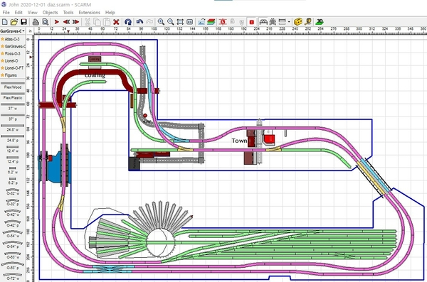
Anyway, here how I’d do it. The gray whisker tracks are optional and depend on how much reach you want to give up. They only impact the purple tracks and right end of the double-crossover. If I had that many engines, I’d deal with the reach issues. BTW, the outline is where the original RH and TT were.

john 2020-12-01 daz

Attachments

Images (1)
  • john 2020-12-01 daz
Files (1)
@DoubleDAZ posted:

John, I’m not sure trying to fit a 34” turntable gets you anything. I don’t how big your largest engine is, but I suspect it will fit on the Ross 27” model. My largest is a 4-6-0 with tender and it’s only 17”. That leaves a whopping 10” for something bigger.

My biggest concern is how far you already are from the double-crossover. You can still reach it from the corners of the RH area, but expanding that area simply increases the potential difficulties dealing with derailments, etc. I don’t foresee problems with the curves or landscaping in the lower left corner once they’re done unless you decide to renovate at some point, but dealing with a renovation once every few years or so is quite different than perhaps having to deal with a pesky switch every time you run trains.

I’ve given you a way to store a large engine in the RH. However, since that might limit that stall’s use, I changed some other things around to provide an option to park it outside the RH between the 2 yard leads. The other thing is that unless you plan to have several large engines, there’s just no need to use 37” tracks for all the whisker tracks.

Anyway, here how I’d do it. The gray whisker tracks are optional and depend on how much reach you want to give up. They only impact the purple tracks and right end of the double-crossover. If I had that many engines, I’d deal with the reach issues. BTW, the outline is where the original RH and TT were.

john 2020-12-01 daz

Yes I Totally agree on the reach for the double cross over. Since the yard entrance is relatively some distance from the DBX Since the grades aren't too steep yet, the DBX can be moved to the right some distance, so as to not reach over the RH to deal with the derailment issue of the DBX

Your thoughts?

@Mark Boyce posted:

John, writing on just the information here and your roundhouse topic, it seems to me the Ross-Korber combination would work best for you.  The Atlas combination would eat up too much room.  Millhouse turntables are great, but expensive as one would expect for the quality and features.  Again, I have no practical experience on the topic, just hashing through all the great information everyone has posted in reply to your questions.

Good to hear your thoughts on this as your opinion is certainly valued! I am hoping a four stall RH will fit.

Thanks again john

John, if you lower the bridge to 6", here's what things look like. I evened out the switches on both sides of the river, so that section is now flat. I also changed the 2 switches on either side of the town to an even 2.5" and 4.0". That put the left switch 6.5" below the 9" outside mainline. Your steepest grade is now 2.5%.

John 2020-12-01b daz

Attachments

Images (1)
  • John 2020-12-01b daz
Files (1)
John 2020-12-02b daz@DoubleDAZ posted:

John, if you lower the bridge to 6", here's what things look like. I evened out the switches on both sides of the river, so that section is now flat. I also changed the 2 switches on either side of the town to an even 2.5" and 4.0". That put the left switch 6.5" below the 9" outside mainline. Your steepest grade is now 2.5%.

John 2020-12-01b daz

@DoubleDAZ posted:

John, if you lower the bridge to 6", here's what things look like. I evened out the switches on both sides of the river, so that section is now flat. I also changed the 2 switches on either side of the town to an even 2.5" and 4.0". That put the left switch 6.5" below the 9" outside mainline. Your steepest grade is now 2.5%.


Great job as always Dave! Looks like things are shaping up nicely. Now I need to fit in buildings, scenery and benchwork. Dave if you do any more enhancements, please use this file as I think I have made all track tinplate and not stainless. It will help me in the parts listing to get a general idea of the quantity of track this project will require. Thanks

Attachments

Images (1)
  • John 2020-12-02b daz
Files (1)
Last edited by Aegis21

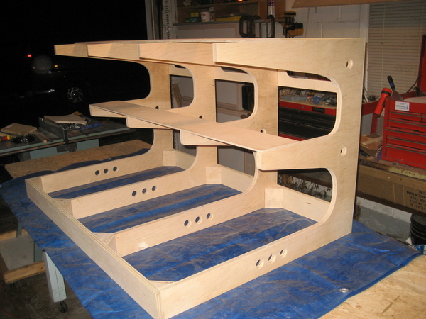
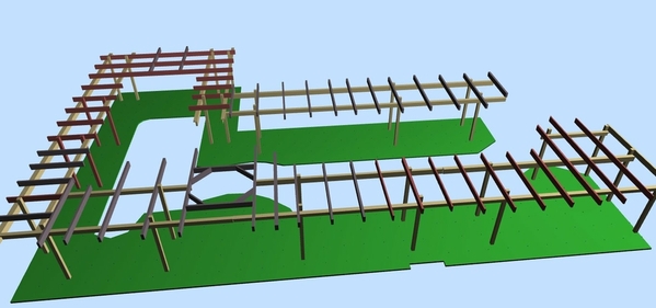
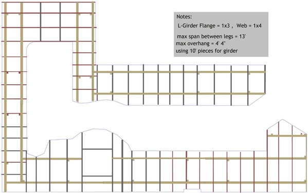
With everyone's help, comments, suggestions, knowledge, especially Dave, Mark and many others . Here is the present state of the design with first attempt at bench work.  If anyone sees any faults or improvements with the bench work or track plan, please shout out. Even if you suggest starting over, all comments are welcome. I almost, never take offense and try to keep an open mind. Again Thanks to everyone!BenchWork_12_04John 2020-12-04John 2020-12-04a

Attachments

Images (3)
  • BenchWork_12_04
  • John 2020-12-04
  • John 2020-12-04a
Files (1)

This has been my favorite thread to follow since it's inception. It's a testament how lucky we ORG Forum members are to get support from this awesome community. Shout out to Dave D who never gets tiered of helping others and Mark B for always encouraging. I look forward to this layout coming to fruition.

Last edited by Dave Ripp.
@Dave Ripp. posted:

This has been my favorite thread to follow since it's inception. It's a testament how lucky we ORG Forum members are to get support from this awesome community. Shout out to Dave D who never gets tiered of helping others and Mark B for always encouraging. I look forward to this layout coming to fruition.   

I TOTALLY agree on ALL the help and effort put into these projects by everyone. Cannot thank Dave and Mark enough and everyone else on this forum.

THANKS!

John

John, Thank you very much!!  I don't know if a 13-foot maximum span between legs is too much.  I would have shortened that since where I see the long spans, there are shorter spans right beside.  I also wonder if it would be good to have legs close to where the turntable will be.  Maybe they won't help and would just get in the way.  These are all questions.  I hope someone who has built a layout of this size will offer some practical answers.

Mark,
I couldn't find any 13' sections, so I don't think John updated the Notes after adding legs above the river.

John,
Since your L-girder rails will be constructed using 10' lengths of 1x material, you won't have a span greater than 10'. I haven't found any standards on how far apart legs can be placed. Using 10' as an example, if you place them 1' in on each end, you'll end up with an 8' span and a 1' overhang.

I put my spin on it. First I changed the grid in SCARM to 16" and aligned the main joists on them. I spread out the 2 joists around the river, so you don't have a joist in the middle of the river and can make the river as deep as you want. I'm not sure why the staggered girder setup that I circled in the lower left corner, but I didn't change it. I also didn't change the different length girders under the river, but I would if it were me.

Mark mentioned the legs near the turntable frame, but I didn't move them because I don't know if it will make a difference.

Just a note. Since I see you drew some L-girders, I want to make sure you know the 1x2 (or 1x3) flange goes on top of the 1x4 girder, not alongside.

As always, these are just my $.02 and food for thought, I've never used L-girder. Most modelers keep their joists (and crossmembers) somewhat symmetrical, like 16" on center, or 24" like Mianne, so that's pretty much what I did.

John 2020-12-04 daz

Attachments

Images (1)
  • John 2020-12-04 daz
Files (1)

Dave, yes I read it from the notes.  I made my joists on top of my metal wall brackets 16” centers, one per wall stud.  Yes the Mianne part is 24” centers.  It doesn’t seem to sag.  
That’s a good move, putting the l-girders on either side of the river.  If I hadn’t planned for it, I would be moving my river when I started building it!  LOL

@Mark Boyce posted:

John, Thank you very much!!  I don't know if a 13-foot maximum span between legs is too much.  I would have shortened that since where I see the long spans, there are shorter spans right beside.  I also wonder if it would be good to have legs close to where the turntable will be.  Maybe they won't help and would just get in the way.  These are all questions.  I hope someone who has built a layout of this size will offer some practical answers.

Lumber yard had 10 foot 1x 4's and 1 x 6's . The 1x6 I ripped into two 1x3's for the flange of the l-girder

Going from Lin Wescott's book the longest span for that I-girder is at least 14 feet I'll double check in morning. Although the longest wood I have is 10 feet so that should be good

I'll move the legs away from the TT to allow more floor access under the TT

Thanks

@DoubleDAZ posted:

Mark,
I couldn't find any 13' sections, so I don't think John updated the Notes after adding legs above the river.

John,
Since your L-girder rails will be constructed using 10' lengths of 1x material, you won't have a span greater than 10'. I haven't found any standards on how far apart legs can be placed. Using 10' as an example, if you place them 1' in on each end, you'll end up with an 8' span and a 1' overhang.

I put my spin on it. First I changed the grid in SCARM to 16" and aligned the main joists on them. I spread out the 2 joists around the river, so you don't have a joist in the middle of the river and can make the river as deep as you want. I'm not sure why the staggered girder setup that I circled in the lower left corner, but I didn't change it. I also didn't change the different length girders under the river, but I would if it were me.

Mark mentioned the legs near the turntable frame, but I didn't move them because I don't know if it will make a difference.

Just a note. Since I see you drew some L-girders, I want to make sure you know the 1x2 (or 1x3) flange goes on top of the 1x4 girder, not alongside.

As always, these are just my $.02 and food for thought, I've never used L-girder. Most modelers keep their joists (and crossmembers) somewhat symmetrical, like 16" on center, or 24" like Mianne, so that's pretty much what I did.

John 2020-12-04 daz

Dave, Thanks for checking drawing for 13 sections My scare skills are beginner at best, so I could have unintentionally drew a 13 footer. I think the longest span Linn Westcott has listed is 14 feet I'll check in am  Thanks for the clean up and making grid 16 inches shows why you are the wizard of scarm! Staggered legs was to keep under table access open. That set up should be more than adequate for stability. If not I'll adjust during build.

Thanks a ton

John, I could be wrong, but I think Mark was saying he wasn’t sure if the legs should be closer to the turntable section for stability, but I get your point about access. However, I don’t think you need to move them any further away. In fact, if you do put all those whisker tracks there and store engines on all or most of them, that’s going to be quite a bit of weight. Tom Tee might be able to shed some light on leg placement in that area. BTW, I believe most people put angled braces in the corners of the square for the turntable creating an octagon inside.

Regarding the area I circled, I have no problem with the leg arrangement, I was just curious why the rails were staggered and why the inside rail going up/down stopped short of the wall?

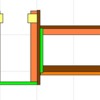
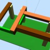
Here are 2 ways I envision rails being joined. One way (Photos 1&2) is with (yellow) sister cleats across the outside of the rails. The other way is (green) end caps butt-joined to each other. Use of end caps also allows  a set of L-girders going in one direction to be butt-joined to a set going in the other direction (Photos 3&4), like in the lower left corner and the upper corner to the left of the town in your design. Of course, you can screw through the rails into the ends of the connecting rails, but I think using end caps gives a strong joint and I think Photo 4 is stronger than staggering the L-girders and doesn’t affect placement of the legs.

Just more food for thought. Like I said, I’ve never used L-girder and the photos I’ve seen don’t show joints.

l-girder

l-girder 3d

l-girder joint

l-girder joint 3d

Attachments

Images (4)
  • l-girder
  • l-girder 3d
  • l-girder joint
  • l-girder joint 3d

John 2020-12-05 dazOf course great ideas Dave. As for specifications for benchwork, these are from Linn Wescott's book how to build model bench work second edition page 35 fig.2

  • The longest span between two sets of leg supports is 13 feet with 1x4/1x2 L-girder       
  • The longest L-girder over hang is 4'-4"  so longest L-girder is 21'-8" (I cannot transport lumber that long LOL)
  • The longest canterliver for joists measuring 1x4 is  30"
  • Support girder distance is 7'-6"

So these are the parameters I tried to follow.

I did put corner braces in the TT "box" that did not show on pics. not sure why???

Thanks a ton Dave for the great graphics and joinery ideas for the girders. Also the load on the whisker area you pointed out could be large (if I only won the lotto and had that many loco's) So I will revisit that and make some calculations based on Linn's book.

Thanks Mark & Dave for being so diligent and helpful!

Attachments

Images (1)
  • John 2020-12-05 daz
Files (1)
Last edited by Aegis21
@Mark Boyce posted:

Dave is right on what I wondered about the legs by the turntable.  I don’t think they should be moved farther away from it.   It has been so long since I read Westcott’s book I don’t recall at all what his recommendation is.  I generally over do my building

Hi Mark, It is ALWAYS better to over build than under build! The distance between supports is one of L-Girders huge advantage. 1x4's do not have huge moment of deflections within 8' and cantilever strength is 30" My mechanical engineering professor explained safety factor - If you are building a walkway over a two foot culvert safety factor could be as low as 1.01 When you design the cables for the elevators in the empire state building it should be a little more (tongue in cheek)  Safety factor always determines how much you over build something. It is not a case of, if you should over build, it is a case of how much you should over build.  So like you I have always over built. 

Thanks John

John, You learned about safety factors in mechanical engineering.  I learned about safety factors in electronics engineering. 

My copy of Lynn Westcott's book must be boxed up in the closet under the stairs which I stored there when we moved here over 9 years ago.  I have never had room to get all my railroad books out.  The stairs have a landing in the middle and turn back in the reverse direction.  That lowest spot behind a wall is where the boxes of books are.  Several years ago, I emptied the closet of empty train boxes and other items once and got out the books I thought I would use.  It isn't on the shelf with the others I removed.

I had forgotten the maximums were so large, since my little layouts never came close to the maximums.  I'm glad you have that reference book!!

@Aegis21 posted:

Hi Mark, I know all to well on having things packed away! LOL The pages are falling out of this book I have read it so many times. I am a slow learner.

I did major in electronics and minored in mechanical. So long ago, I have forgotten all but the funny stories!

I took a slide rule into work almost 20 years ago now to show a younger coworker.  I couldn't remember how to use it.  I would even have to look up Ohm's Law to make sure I got it right.  I even graduated Magna Cum Laude, but what good did it do me??  I was always behind the curve on promotions and raises wherever I went.  Yet my uncle was a very average student.  He became an aerospace engineer with Boeing, worked on the Apollo project at Huntsville and Cape Canaveral and earned more money than they can use! 

Your wife is correct, a functional yard takes up a lot of room.  Personally, I think you have a nice long run around the room even with the yard.  I would keep it pretty much as the latest design shows.

I don't want to sound rude, but your wife is kind of stating the obvious to a model railroader.  The only way to shrink a yard is to cut the number of tracks (from 6 to 2 as an example) or to shorten the length of all yard tracks.  Beware, though, that shortening too much may result in one or two tracks not being worth the cost of the switches to build them.

Also, as noted earlier, you can modify your "engine" area by eliminating everything but the turntable and the approach tracks.  There may be other answers, but it would help if we knew your wife's real concerns (cost, scenery space, time to build, complexity of wiring & maintenance?).

You might also show her pictures of Frank Ellison's 'Delta Lines' that he ran as a true point-to-point O gauge operation with a nice yard on each end and a middle "division point" yard.  Then turn to her and brag that you are conservatively building only one yard.  Seeing what you could (but don't) want sometimes turns the tide.  Alternatively, offer her a big section across from the yard that she can scenic and manage anyway she wants.

Chuck

Last edited by PRR1950
@Aegis21 posted:

Dave, How do I print out a magnified section of the benchwork in scarm? I tried snapshot in scarm which didn't work for me. got the entire plan I could use photoshop but wanted to avoid the extra work.

Thanks

The only way I know how to do it is to zoom in on what you want to print and capture a screenshot. I use the Windows Snip & Sketch tool to do that. I don’t know any way to do it from SCARM or Chrome directly. I could be wrong, but  I think you get a better print zooming in for the capture vs doing the capture and then cropping.

@Aegis21 posted:

Ok I know it is getting late in the game, however my wife pointed out the yard takes up a huge amount of real estate. Other than doing away with entire yard I haven't a clue on how to shrink the yard without destroying the functionality. anyone with suggestions?

The only time it’s late in the game is after tracks have been laid and she says that. 😉 The question is how much functionality do you want? For example, if you only have 5 engines and a standard amount of cars, then 2-4 trains will be operating, leaving half or less in the yard. If you’re trying to save money on switchers, then you can reduce the number of spurs, eliminate the runaround track and if you’re content to back trains in, you can even eliminate the escape crossover. You can still break down and build up trains, just not prototypically. You can also eliminate all those whisker tracks and leave some trains parked on the mains between running sessions. A yard like yours is expensive and IMHO way more than you need, other than for appearance. If I was building it, I wouldn’t even have the roundhouse, just open whisker tracks, maybe with a dual-stall engine house, or even a single-stall. I’d have the 27” or 28” turntable and 5 yard spurs.  But then I don’t plan to break down or build up consists. I can play with it, but it’ll be later today.

@DoubleDAZ posted:

The only time it’s late in the game is after tracks have been laid and she says that. 😉 The question is how much functionality do you want? For example, if you only have 5 engines and a standard amount of cars, then 2-4 trains will be operating, leaving half or less in the yard. If you’re trying to save money on switchers, then you can reduce the number of spurs, eliminate the runaround track and if you’re content to back trains in, you can even eliminate the escape crossover. You can still break down and build up trains, just not prototypically. You can also eliminate all those whisker tracks and leave some trains parked on the mains between running sessions. A yard like yours is expensive and IMHO way more than you need, other than for appearance. If I was building it, I wouldn’t even have the roundhouse, just open whisker tracks, maybe with a dual-stall engine house, or even a single-stall. I’d have the 27” or 28” turntable and 5 yard spurs.  But then I don’t plan to break down or build up consists. I can play with it, but it’ll be later today.

Dave, Thanks for the input, no need to do anything right now. The cost of turnouts is not a consideration, as I would rather wait and have proper funding for what makes a good layout than regret moving fast and wishing I hadn't. Before my wife even chimed in I was concerned how dominate that 20'x4' flat yard area would be and would I use it as it should be used. I do love the TT & RH however if it is too much well it is too much.

John, as we always say, it’s your layout, your time and your money. 🤪 You can still reduce the size of the yard by 2 tracks and reduce the number of whisker tracks while keeping the other functionality. Maybe she just can envision the landscaping with buildings, elevations, etc., and that’s why it looks overbearing.

@DoubleDAZ posted:

Couldn't resist downsizing a bit to see what it would look like.

John 2020-12-05 daz

That is looking good, I had at the same time moved the two main lines closer buy the yard/ wall bump. Here is that scarm file.  Would you please incorporate this change into that file so my wife can see the full effect? No rush if you decide to do it.  It also has the bridge entry cleaned up to have both angles at 60 degrees Hopefully I didn't mess up grades or anything else....John 2020-12-06 daz

Thanks

John

Attachments

Images (1)
  • John 2020-12-06 daz
Files (1)

John, here you go. The changes did raise the max grade to 2.8% going to the bridge, but the grades will undoubtedly change a bit as you add in the slope transitions.  People push for grades =<2%, but modern engines can do 5%, so anything =<3% is more than reasonable.

I did change some of the flex tracks because they were "weaving" in opposite directions.
I flattened the switches and spurs that you added.
I moved the escape crossover in the yard a bit, but the exact position will depend on how much room you'll actually need. Please note that it doesn't have to be long enough for your largest engine because you can always disconnect a large engine and use a switcher to pull the cars into the yard.
I fixed the lengths of the yard spurs.

John 2020-12-06a daz

Attachments

Images (1)
  • John 2020-12-06a daz
Files (1)

Thanks Dave! Looks like there is now wiggle room. I am tempted to do away with one or two more whisker tracks. I'm actually cutting legs for benchwork in the garage! Hoping to get general ideas for layout finished enough to start on girders and top. I'm planning on making one 4' x 8' section and then see what reach is needed and where I may need to scale back or can live with the TT bump out.

Thanks for being so through, flattening the switches etc. Really appreciated!

@DoubleDAZ posted:

Here's yet another option that I think looks cleaner and more balanced.

John 2020-12-06b daz

Yes Dave definitely cleaner and balanced! Nice job!

I might have gotten things out of balance with moving river/bridges down a bit and moving yard switch back to the left.  I am trying to keep in mind the reach factor and putting in scenery/buildings etc.

Please all take a look and add comments and definitely criticisms... Again Thanks All!

On another note all legs supports have been cut, holes drilled for 3/8-16 tee nuts and bolts for leveling. drilled to accommodate 4" bolts to allow for raisining the table up a couple inches if it seems too low. Now if I can stop procrastinating and actually decide on a final layout, then joists can be cut. I have six L-Girders cut, screwed and glued that are 10' long. So I could put together a "bench" section 48 inches wide by 10' long. I have a spare 4x8 Sheetrock which I could throw on top and check reach and work-ability. Is that a word? Thanks in advance.  JohnJohn 2020-12-08a daz

Attachments

Images (1)
  • John 2020-12-08a daz
Files (1)

John, I think Dave’s last plan will help with the reach.  I definitely think setting up the section with the sheet rock will help you decide on the reach and height issues.  The 4” bolts will give you some nice leeway on height.  I would suggest just building Benchwork along one Wall, lay some track, and wire it To run a train back and forth before building all the benchwork and then realizing it is way to high or too short

@Mark Boyce posted:

John, I think Dave’s last plan will help with the reach.  I definitely think setting up the section with the sheet rock will help you decide on the reach and height issues.  The 4” bolts will give you some nice leeway on height.  I would suggest just building Benchwork along one Wall, lay some track, and wire it To run a train back and forth before building all the benchwork and then realizing it is way to high or too short

Yes Mark, Dave did a great job!

Mark, you give sage advise with setting up a trial section for height and reach

@Aegis21 posted:

Yes Mark, Dave did a great job!

Mark, you give sage advise with setting up a trial section for height and reach

Thank you, John.  I have seen online, whether here or other forums or email groups in the past, where someone raised a layout larger than yours, and someone else lowered a layout larger than yours.  Certainly not a one man-Saturday afternoon job by any means.  I wouldn't wish that dilemma on anyone!! 

Last edited by Mark Boyce

Mark, I'm sure you mentioned it, but how high is your layout. At this time my base will be 40" and could use adjustment to go to 43"  Hoping this will be a good height with elevations and mountains. Most likely the only area that will be at baseline level is the yard and roundhouse. I also have the option to use some styrofoam to increase elevation and provide places for drainage ditches etc.

@Dave Ripp. posted:

John, Remember the higher the table is the harder it is to reach over scenery. Hight can negatively affect your reach which is pushed with your yard and elevations. Just my opinion.

Hi Dave,  I do not have any experience at all for making this call. What would be a good height range in your opinion? 37-40   40-43    43-46    etc???  Right now it is easy to cut down to lower the overall height. In fact I would start with all new legs at 50" or 20" I do not have an good idea. it seemed 38-42" seemed good for me sitting on a rolling stool and my wife standing I am 6' wife is 5' 1.5"

Thanks

John, when it comes to height, there are a lot of variables. Of course, you have to consider reach, but if you have to reach that often, then something probably needs fixed; a quirky switch, misaligned tracks, underweight rolling stock, etc. And you have to consider getting underneath to work on wiring, but once built, how often? Most folks seem to be comfortable with 40-42", but some folks like to look down on the operation or sit down while operating, so I've seen them as low as 36". The easiest way to judge is to take your dining room table and raise it with 2x4 blocks or something to see what's most comfortable for you. Set up some tracks and run a train back and forth. If you have a 2x4, set some tracks on that and raise one end to see about grades.

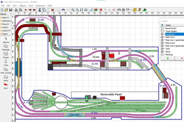
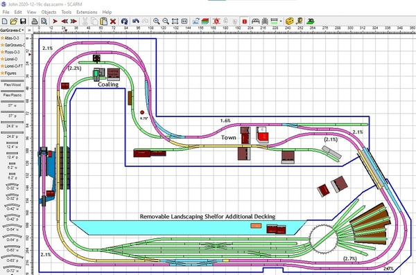
Anyway, here's a version of your latest changes. You can't just throw flex track in to make things fit. I aligned things for clearance, including moving the mains closer to the wall to get enough clearance from the yard. I also straightened the track coming off the bridge. I added a coaling and water station to the yard, but the coaling station I have is a tight fit. But, just for kicks I added a removable panel along the yard to show how you can have room for landscaping while reducing reach. The panel can be several smaller panels that would connect like those side panels on pickup truck beds. You could fill that small area behind the roundhouse the same way.

John 2020-12-09 daz

Attachments

Images (1)
  • John 2020-12-09 daz
Files (1)

John, The layout I'm currently building is 39.5. I have no elevations and at 5-11 can reach the center which is 36 inches. Once I add scenery I suspect it will be a little tougher but my table is 6 x 20 with access to both sides. You don't  want to have to climb up to reach things as scenery gets damaged and I have a top side creeper from my old larger layout but never enjoyed dragging it around for use. I would do the 37 to 40 as this will be more comfortable to reach over things. I'm sure others will have thoughts on this to.

John, Mine is 43" high.  The top of the grade is 50" high.  I had planned on 42" and 48", but somewhere I goofed on the base measurement, so it wound up at 43.  I decided I needed another inch of clearance at the underpass, so 48 became 50.  I can measure a half dozen time with the same result and still goof things up.  With 29" deep shelves it works okay for me except that spot where I decided later on to put in the switch going off the mainline to the wye.  That is because the peninsula going to the lift up bridge is in the way.  I stood on a 2-foot high step up platform to put that switch in and it wasn't bad at all.  I am 5' 11" tall also, but less agile than Dave Ripp I would think.  That's the price I pay for always thinking of things after the fact. 

Actually I like it higher than many folks.  My N-scale layout was 50" high as I recall, although I was half my age now when I built it.

@DoubleDAZ posted:

John, when it comes to height, there are a lot of variables. Of course, you have to consider reach, but if you have to reach that often, then something probably needs fixed; a quirky switch, misaligned tracks, underweight rolling stock, etc. And you have to consider getting underneath to work on wiring, but once built, how often? Most folks seem to be comfortable with 40-42", but some folks like to look down on the operation or sit down while operating, so I've seen them as low as 36". The easiest way to judge is to take your dining room table and raise it with 2x4 blocks or something to see what's most comfortable for you. Set up some tracks and run a train back and forth. If you have a 2x4, set some tracks on that and raise one end to see about grades.

Anyway, here's a version of your latest changes. You can't just throw flex track in to make things fit. I aligned things for clearance, including moving the mains closer to the wall to get enough clearance from the yard. I also straightened the track coming off the bridge. I added a coaling and water station to the yard, but the coaling station I have is a tight fit. But, just for kicks I added a removable panel along the yard to show how you can have room for landscaping while reducing reach. The panel can be several smaller panels that would connect like those side panels on pickup truck beds. You could fill that small area behind the roundhouse the same way.

John 2020-12-09 daz

Thanks Dave for your input on layout height much appreciated. Great to have as many view points as possible.

A double thanks on straightening out the stuff I mess up with cheating flex track. Great idea with the drop down panels in front of yard. It appears there is still enough walking room and much needed tabletop room in that area. I would be tempted to suare off the TT area by extending that drop down panel(s) to the left another 2 feet I Am hoping to have time today to put up an L-grider section with a 4x8 sheet of either plywood or sheet rock, to check reach and height.

Aggain Thanks for all your work and input

@Dave Ripp. posted:

John, The layout I'm currently building is 39.5. I have no elevations and at 5-11 can reach the center which is 36 inches. Once I add scenery I suspect it will be a little tougher but my table is 6 x 20 with access to both sides. You don't  want to have to climb up to reach things as scenery gets damaged and I have a top side creeper from my old larger layout but never enjoyed dragging it around for use. I would do the 37 to 40 as this will be more comfortable to reach over things. I'm sure others will have thoughts on this to.

Hi Dave, I am a bull in a china closet, so I get the "scenery gets damaged" statement. Hoping to get a top side creeper as that will be the only way to work on the layout passed 30-36" reach. So I will have to wait and see how that will reall work out for e. Have read lots of pros and cons on creeper. I am taking into account for the creeper footprint with my bench work legs and bracing. I am leaning toward 40" as ground zero at this point. Hopefully I will get a section thrown up to have a good test of reach and visual perspesctive.

Thanks for the input, much appreciated.  John

@Mark Boyce posted:

John, Mine is 43" high.  The top of the grade is 50" high.  I had planned on 42" and 48", but somewhere I goofed on the base measurement, so it wound up at 43.  I decided I needed another inch of clearance at the underpass, so 48 became 50.  I can measure a half dozen time with the same result and still goof things up.  With 29" deep shelves it works okay for me except that spot where I decided later on to put in the switch going off the mainline to the wye.  That is because the peninsula going to the lift up bridge is in the way.  I stood on a 2-foot high step up platform to put that switch in and it wasn't bad at all.  I am 5' 11" tall also, but less agile than Dave Ripp I would think.  That's the price I pay for always thinking of things after the fact. 

Actually I like it higher than many folks.  My N-scale layout was 50" high as I recall, although I was half my age now when I built it.

Mark you layout is coming along fantastically! Cannot believe your shelves are 29 inches. Comparing our layouts, it seems I am trying to cram too much track into any given area. Track per square foot on my layout has to be a lot more than yours, yet your layout appears much more functional and realistic. You are doing a great job!

@Mark Boyce posted:

I think other than the yard area your plan doesn't have any more track per square foot than mine.  You have plenty of room for scenery and buildings.

The room looks great and ready for a layout!!

This has always been my achilles heel, visualizing the potential in a space. Maybe when track gets laid down I will get a better feel for the scenery and terrain. It is funny, I keep on putting buildings in front of track as if the track were a road.... LOL I need to clean out some more boxes, just am running out of room. I am hoping to use under table storage, however that doesn't help during construction. That old work bench in the back is 38" high and I am leaning towards that for table base height

Last edited by Aegis21

One of the biggest problems is getting folks to measure or get the footprint (length, width and height) of buildings, accessories, etc., that they have or plan to buy. It doesn’t take much to create an object in SCARM to those dimensions and move them around the layout to see where they might fit. Some have been created in more detail here.

Last edited by Rich Melvin

Hi Dave, Just finding out what the sizes are for things you may want to purchase is either easy or almost impossible, nothing in-between. I have made some buildings and got the bascule bridge from the site you posted. I hope it is a close fit as that one is not that tight to begin with, except the control building on one side, which you picked up on quickly. The building I did were not very well detailed or close to mimicking the real structure in architecture, more of a foot print and height perspective for placing on scarm for general fit overall appearance. I am sure once benchwork is done and track laid, roads and buildings will be adjusted as the track changes and looks dictate. Off to cut a pile of gussets and put together first L-girder span. Have a great day All! Again many thanks for all the help everyone provides!

John, good deal on mass producing L-girder parts!!

I agree about the problems getting building sizes to use in planning.  Having built layouts in HO and N scale, I am finally starting to get in the groove on O scale sizes.  I have sold 4 or 5 built-ups to other Forum members at a good discount not having the heart to cut up some wonderful buildings.  I got the dimensions for the Carolina Craftsman Kits Thomas, West Virginia station from the manufacturer and knew it would fit.  Then a fellow on a Western Maryland Modeler's group who is switching from O 2-rail to HO is selling all his buildings.  He is the one who I bought the Thomas engine house from.  It is actually CCK O scale prototype after they did it in HO.  I got the dimensions and knew I could squeeze it in one of two spots.  Squeeze is the word for all those following my layout build.  This guy also had the Elkins, West Virginia station built up for sale, but it is massive!  The prototype has been refurbished in Elkins.  Both Thomas buildings were demolished long ago.

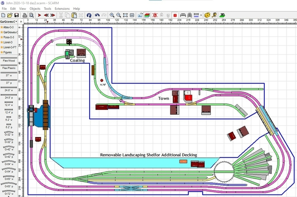
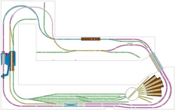
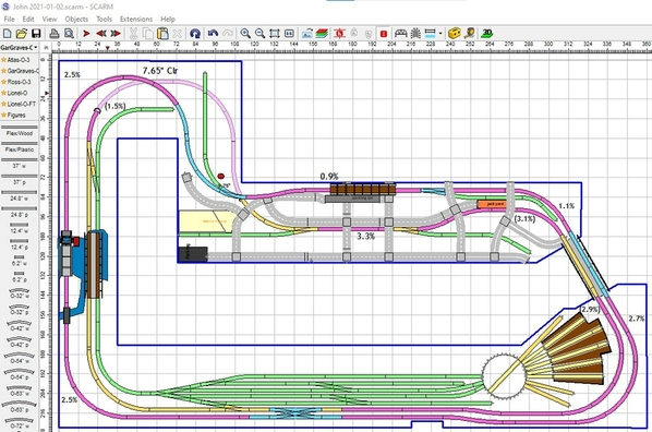
John 2020-13-18Hello All !  Been messing around with getting more space around the yard area and making the roundhouse/turntable area more accessible. The right side of the layout does not have walls so I tried to fit the TT/RH on that side which is more accessible. I am sure I messed up the functionality of the yard with trying to incorporate that 4 way yard switch. I am almost embarrassed to post this layout as I am sure there are lots of mistakes and will show how little I know about yards and railroading. Let me know if this is totally foolish and how to fix/improve or scrap. Thanks in advance.

John

Attachments

Images (1)
  • John 2020-13-18
Files (1)
Last edited by Aegis21

Two comments:

1. Your lower level / interior mainline now runs through the curve portion of two switches to cross the river and avoid entering the yard.  Since it's a lot easier for long trains to go through the straight leg of switches, try moving the same mainline closer to the other mainline at the river crossing, but leave your yard lead entrance "north" of the river.  Will require another bridge, but provide a nice long yard lead and a straighter mainline.

2. You've had this problem for a while and I'm not too sure how to fix it.  Trains leaving the yard with the engine in the lead can only run counter-clockwise.  That means: a) to run a train clockwise, it must be backed out of the yard and on to the mainline, and b) to bring a counter-clockwise running train into the yard, it must be backed into the yard a long distance.  A train able to enter / depart the yard from both directions at least allows multi-direction travel, even if no reversing is possible.

Of course, #2 might be moot because your mainlines have no passing sidings away from the yards. So maybe two trains running counter-clockwise is all you plan to do.

Chuck

Last edited by PRR1950

John, I have to say you like to play fast and loose with flex track, so I cleaned those up to remove some squiggles and tight curves. I moved the TT and added the RH back. Note I smoothed out the baseboard and added the removable shelf for landscaping. IMHO, it doesn't make sense to make the changes you made unless you deal with reach along that stretch.

That said, I think you've taken a few steps backwards.
- The top yard lead and crossover don't make any sense to me. You can pull a train in and disconnect the engine, but then what? There's no way to break down the cars, if that's what the crossover is supposed to be for.
- I'm not sure you need all those tracks connecting to the TT.

John 2020-13-18 daz

However, here are some options I think you should consider:

John 2020-13-18 daz2
Trains would arrive on the Yellow track where the engine disconnects to return to storage. A switcher then breaks down the arrival train and prepares a departure train on the Blue track. An engine uses the top yard track to come out of storage and go down to pick up the departing train. If you want a train to go counterclockwise, 1 engine will pull the train out and temporarily foul mainline2 until another engine picks it up. When trains return, they will either have to back into the arrival track or a switcher will have to pull them in.

John 2020-13-18 daz3
I
n this version I changed the elevations of the yard, lead tracks and double crossover to 43" and added the crossover to the Blue tracks. An arriving train still has to back in, but can do so without straddling the bridge too much. In this case, a departing train would have to be prepared on the Yellow tracks.

I just noticed I put a stream through a building for the small bridge you added. Oh well, that's an easy fix. I'm sure I missed something else or there's a better way, so we'll see what others have to say.

Attachments

Last edited by DoubleDAZ

Chuck, both good points. I was going to do something about the bridge situation, but haven't had time to bring it up. I thought I mentioned it some time ago, but may have decided to drop it until I had time to offer a solution. I just notice John added another bridge, so maybe that could be moved. Even though it's just a model railroad, I don't like trains having to go through that many switches using the curved part.

And you'll see in my post a bit ago, I mentioned the direction problem. I'm not sure fouling the main to back into the yard though is a big deal. Mainlines get fouled all the time in reality. We often see trains stopped along I-10 and I-40 all the time waiting for other trains to get out of the way. Granted, it's not ideal, but I don't see a solution given John's desire for elevation changes, etc. The only solution that's been mentioned is a 2nd bridge across the entryway. There are spurs on both sides that could be joined easy enough to make the yard a through yard. Add in changing the bridge on the left to make a longer lead. I may work on doing that after I get my shower.

@DoubleDAZ posted:

John, I have to say you like to play fast and loose with flex track, so I cleaned those up to remove some squiggles and tight curves. I moved the TT and added the RH back. Note I smoothed out the baseboard and added the removable shelf for landscaping. IMHO, it doesn't make sense to make the changes you made unless you deal with reach along that stretch.

That said, I think you've taken a few steps backwards.
- The top yard lead and crossover don't make any sense to me. You can pull a train in and disconnect the engine, but then what? There's no way to break down the cars, if that's what the crossover is supposed to be for.
- I'm not sure you need all those tracks connecting to the TT.

John 2020-13-18 daz

However, here are some options I think you should consider:

John 2020-13-18 daz2
Trains would arrive on the Yellow track where the engine disconnects to return to storage. A switcher then breaks down the arrival train and prepares a departure train on the Blue track. An engine uses the top yard track to come out of storage and go down to pick up the departing train. If you want a train to go counterclockwise, 1 engine will pull the train out and temporarily foul mainline2 until another engine picks it up. When trains return, they will either have to back into the arrival track or a switcher will have to pull them in.

John 2020-13-18 daz3
I
n this version I changed the elevations of the yard, lead tracks and double crossover to 43" and added the crossover to the Blue tracks. An arriving train still has to back in, but can do so without straddling the bridge too much. In this case, a departing train would have to be prepared on the Yellow tracks.

I just noticed I put a stream through a building for the small bridge you added. Oh well, that's an easy fix. I'm sure I missed something else or there's a better way, so we'll see what others have to say.

Thanks Dave ! Yes you are being polite about my use of flex track. I use it to see if the plan is at all possible, then to look at overall design to see if it made things better, worse or no difference.

I do not have the railroad/big layout yard experience to make intelligent changes. So all your help and those of others is totally welcome.  I love the idea of the removable shelf, not sure how to implement it with bench work and scenery. Guess that is another challenge that needs to be met, although certainly possible, otherwise you would not have put it in! 

@PRR1950 posted:

Two comments:

1. Your lower level / interior mainline now runs through the curve portion of two switches to cross the river and avoid entering the yard.  Since it's a lot easier for long trains to go through the straight leg of switches, try moving the same mainline closer to the other mainline at the river crossing, but leave your yard lead entrance "north" of the river.  Will require another bridge, but provide a nice long yard lead and a straighter mainline.

2. You've had this problem for a while and I'm not too sure how to fix it.  Trains leaving the yard with the engine in the lead can only run counter-clockwise.  That means: a) to run a train clockwise, it must be backed out of the yard and on to the mainline, and b) to bring a counter-clockwise running train into the yard, it must be backed into the yard a long distance.  A train able to enter / depart the yard from both directions at least allows multi-direction travel, even if no reversing is possible.

Of course, #2 might be moot because your mainlines have no passing sidings away from the yards. So maybe two trains running counter-clockwise is all you plan to do.

Chuck

Chuck, Great comments and on point! I am pressed for family xmas duties and need to attend them, however I'll return to these asap

Again Big THANKS for the input!

John, just needling you about the flex, I know why you use it and there’s almost always a way to smooth it out. When it comes to the removable shelf, I envision 3 or 4 sections. Truth be told they’re only a foot deep, so I think they could be simple bolt-on’s, but I haven’t given it that much thought. I’ll work on an idea using drawer-like slides.

@DoubleDAZ posted:

John, just needling you about the flex, I know why you use it and there’s almost always a way to smooth it out. When it comes to the removable shelf, I envision 3 or 4 sections. Truth be told they’re only a foot deep, so I think they could be simple bolt-on’s, but I haven’t given it that much thought. I’ll work on an idea using drawer-like slides.

Dave, you can always needle me so I get the point. Lol since the shelf is part of the flat yard, that should be easier to do.

@PRR1950 posted:

Two comments:

1. Your lower level / interior mainline now runs through the curve portion of two switches to cross the river and avoid entering the yard.  Since it's a lot easier for long trains to go through the straight leg of switches, try moving the same mainline closer to the other mainline at the river crossing, but leave your yard lead entrance "north" of the river.  Will require another bridge, but provide a nice long yard lead and a straighter mainline.

Sounds like it would be a good improvement, plus I do have another bridge😀

2. You've had this problem for a while and I'm not too sure how to fix it.  Trains leaving the yard with the engine in the lead can only run counter-clockwise.  That means: a) to run a train clockwise, it must be backed out of the yard and on to the mainline, and b) to bring a counter-clockwise running train into the yard, it must be backed into the yard a long distance.  A train able to enter / depart the yard from both directions at least allows multi-direction travel, even if no reversing is possible.

This issue was the initial rework Of the yard and putting rh/th at other end hoping I would see a solution. I obviously did not come up with anything. Thanks for bringing this up as I was wondering what real operational effect this has on layout. Again thanks! 😃

Of course, #2 might be moot because your mainlines have no passing sidings away from the yards. So maybe two trains running counter-clockwise is all you plan to do.

Chuck

Last edited by Aegis21

John, the direction problem did not arise because you moved the TT or reconfigured the yard, it’s been there all along. IMHO there’s nothing wrong with fouling the inner mainline because you have 2. Here in Phoenix we have a storage yard alongside a mainline that gets fouled all the time by an engine lash up pulling a long string of cars out of the yard then backing up to connect to another string before heading out to California. It’s been a constant irritation at the 59th Ave & Grand Avenue intersection. I used to go through that intersection often and invariably got stopped by trains fouling the mainline there. That’s where the yard ends and goes down to a single mainline heading out of town. I’ll be working on Chuck’s idea to reconfigure the bridge area. I was going to do that some time ago, but didn’t want to mess up the spurs you have there and we were concentrating on the RH/TT area.

@DoubleDAZ posted:

John, the direction problem did not arise because you moved the TT or reconfigured the yard, it’s been there all along. IMHO there’s nothing wrong with fouling the inner mainline because you have 2. Here in Phoenix we have a storage yard alongside a mainline that gets fouled all the time by an engine lash up pulling a long string of cars out of the yard then backing up to connect to another string before heading out to California. It’s been a constant irritation at the 59th Ave & Grand Avenue intersection. I used to go through that intersection often and invariably got stopped by trains fouling the mainline there. That’s where the yard ends and goes down to a single mainline heading out of town. I’ll be working on Chuck’s idea to reconfigure the bridge area. I was going to do that some time ago, but didn’t want to mess up the spurs you have there and we were concentrating on the RH/TT area.

Hi Dave,  I did realize the direction issue and was hoping to flip things around to jog an idea out of this old noggin. That did not occur...  However the access is better for the RH/TT at the right hand end of the layout. So I think something good happened out of luck.  As for the fouling of the second mainline - I Hate to design in an irritation so to speak, however everything is a trade off.

As for bridge area, move whatever needs to be moved, spurs, mainlines, Mt Everest (i know you can do it) I am saying I do not consider anything final or a must have. And yes the RH/TT took priority for sure.

  btw please return to the 12 month calendar on file naming convention. 2020 needs to end!

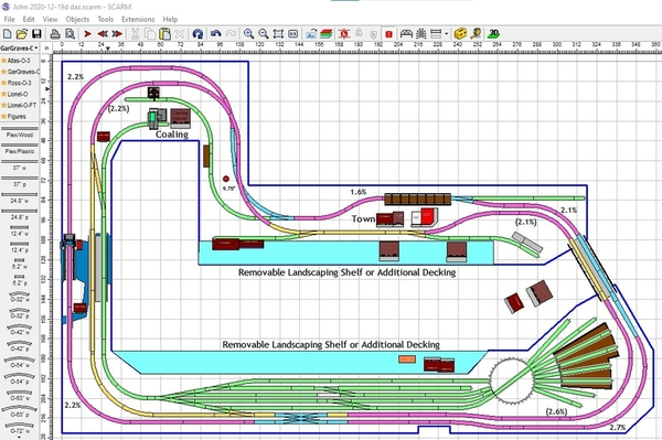
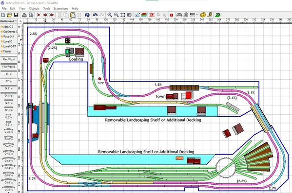
So, here's my latest version. Somehow I lost my SCARM file, so it'll take me a bit to recreate it from a backup.

Ok, thanks to auto backup each time I save that didn't take as long as I thought it would. Somehow the header got corrupted and the original file wouldn't load.

Anyway, I think I addressed all the concerns, though they might not be the most desirable solutions. I thought I mentioned the switch problem across the river and through the town some time ago, they're both the same situation, but maybe I never posted my comments. Be that as it may, mainline2 now runs through the straight section of the switches for the entire run. The yard now allows arrivals and departures in either direction with long lead tracks so there won't be any fouling of the mainline. To do all this, I had to add the 2nd bridge over the river and another cross over the entryway. I know that's not the most elegant solution, but the dual track bridge can be a lift out/up and the new cross can be a simple dropdown or another bridge.

I changed some elevations below the entryway so the out run is a bit higher than the others. That's why the Blue tracks are so much longer than the orange tracks. I updated all the grade and track height labels, so you can take a look at those by turning on those levels.

One question I have is what are the other bridges you already have and how long are they. The ones I used across the river might be too big or not big enough.

John 2020-12-19 daz

Attachments

Images (1)
  • John 2020-12-19 daz
Files (1)
Last edited by DoubleDAZ
@DoubleDAZ posted:

So, here's my latest version. Somehow I lost my SCARM file, so it'll take me a bit to recreate it from a backup.

Ok, thanks to auto backup each time I save that didn't take as long as I thought it would. Somehow the header got corrupted and the original file wouldn't load.

Anyway, I think I addressed all the concerns, though they might not be the most desirable solutions. I thought I mentioned the switch problem across the river and through the town some time ago, they're both the same situation, but maybe I never posted my comments. Be that as it may, mainline2 now runs through the straight section of the switches for the entire run. The yard now allows arrivals and departures in either direction with long lead tracks so there won't be any fouling of the mainline. To do all this, I had to add the 2nd bridge over the river and another cross over the entryway. I know that's not the most elegant solution, but the dual track bridge can be a lift out/up and the new cross can be a simple dropdown or another bridge.

I changed some elevations below the entryway so the out run is a bit higher than the others. That's why the Blue tracks are so much longer than the orange tracks. I updated all the grade and track height labels, so you can take a look at those by turning on those levels.

One question I have is what are the other bridges you already have and how long are they. The ones I used across the river might be too big or not big enough.

John 2020-12-19 daz

Great job as always Dave! Not sure on the added bridge at the entrance. The other bridge I have is MTH RailKing 40-1103 that is 30" bridge with an added girder bridge extension. I do like the river clean up a lot!

John, I knew you wouldn't like the extra bridge over the entryway, but I couldn't resist messing with you.

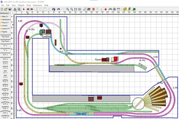
Here's a more elegant alternative that also lets you have arriving and departing trains in both directions. It requires pulling into the yard on to the long lead track and then backing into the yard, but doesn't foul mainline2.

Note that I moved the TT/RH even further right to increase the yard size and give you an extra whisker track. I saw no reason for that spur you had there and you don't gain enough to curve around the TT to extend the bottom yard track, so I left it straight.

Also note that I connected another yard track to the TT. If you do it right, it will allow you to pull a long engine straight across the TT into 2 larger bays instead of just the one I had. There also appears to be room for a 5th stall.

The placement of the crossover into the yard to the left of the double-crossover lets you continue to use the bottom yard track for storage,  Even better though is that when trains depart going counterclockwise they can go through the double-crossover to get to manline1 right away. Conversely, trains going clockwise on mainline1 can also go through the double-crossover directly onto the yard lead and then back in.

I hope you like it. I think we've got a winner here.

John 2020-12-19a daz

And this shows a little of how the removable shelf would work. Note that the joists would extend past the bench work allowing you to simply set the shelf (or series of shelves) on them. I haven't taken the time to reconfigure the L-girder framing, so not all the joists would expend, just enough of them to support the shelf.

test20

Attachments

Images (2)
  • John 2020-12-19a daz
  • test20
Files (1)
Last edited by DoubleDAZ

I have not read through the dozen pages so this comment may be out of line but I do have a thought on the placement of the double cross over.

Double cross overs when not is a congested must do circumstance can be an over done presentation.  On a long tangent dual track mainline a pair of single cross overs would serve the same purpose with less fuss and a present a broader palette  of track work.  Just a thought.

That nice long straight a way would look super with a two pair of #8 single cross overs!

I ride the rails a lot and single crossovers are plentiful.  Double crossovers are usually in tight yard approaches and passenger station entrance/exits.   I have yet to encountered a double crossover on a long tangent dual track mainline.

I agree Dave, I like this plan a lot.  The yard and turntable Roundhouse area look workable.

Tom, I don’t think your comment is out of line.  I have been following since the beginning and don’t recall any discussion on the double crossover.  It could have been early on and I forgot.  Regardless, you have knowledge from the prototype.  It could be John already has a double crossover like the four way switch and it was just a given.

@Tom Tee posted:

I have not read through the dozen pages so this comment may be out of line but I do have a thought on the placement of the double cross over.

Double cross overs when not is a congested must do circumstance can be an over done presentation.  On a long tangent dual track mainline a pair of single cross overs would serve the same purpose with less fuss and a present a broader palette  of track work.  Just a thought.

That nice long straight a way would look super with a two pair of #8 single cross overs!

I ride the rails a lot and single crossovers are plentiful.  Double crossovers are usually in tight yard approaches and passenger station entrance/exits.   I have yet to encountered a double crossover on a long tangent dual track mainline.

Hi Tom,  My lack of knowledge in this area is glaring. I have a double crossover that to me (not knowing better) thought it would enable trains to change main lines utilising something I already had. Sounds like that goes against any realistic railroad.

Guess it could go into the yard????

Thanks for your input!

@DoubleDAZ posted:

John, I knew you wouldn't like the extra bridge over the entryway, but I couldn't resist messing with you.

Dave, you have carte Blanche when it comes to messing with me!

Here's a more elegant alternative that also lets you have arriving and departing trains in both directions. It requires pulling into the yard on to the long lead track and then backing into the yard, but doesn't foul mainline2.

Note that I moved the TT/RH even further right to increase the yard size and give you an extra whisker track. I saw no reason for that spur you had there and you don't gain enough to curve around the TT to extend the bottom yard track, so I left it straight.

Also note that I connected another yard track to the TT. If you do it right, it will allow you to pull a long engine straight across the TT into 2 larger bays instead of just the one I had. There also appears to be room for a 5th stall. Hmmmm, that is enticing 5th stall plus two extended bays!

The placement of the crossover into the yard to the left of the double-crossover lets you continue to use the bottom yard track for storage,  Even better though is that when trains depart going counterclockwise they can go through the double-crossover to get to manline1 right away. Conversely, trains going clockwise on mainline1 can also go through the double-crossover directly onto the yard lead and then back in.

I hope you like it. I think we've got a winner here.

This looks great, I'll try not to mess with it. Now should the yard have some added crossover switches?

John 2020-12-19a daz

And this shows a little of how the removable shelf would work. Note that the joists would extend past the bench work allowing you to simply set the shelf (or series of shelves) on them. I haven't taken the time to reconfigure the L-girder framing, so not all the joists would expend, just enough of them to support the shelf.

The shelves being on top of the joists makes lots of sense. I'll move the joists for the TT and redraw girders and supports.

test20

John,

I’m working on changing the double-crossover, but I don’t think Tom realizes that the “long” dual tracks are at different elevations. Changing the double to separate #8 switches takes 8’ of track, almost triple what the double uses.

When it comes to switches in the yard, I really don’t know. I looked at the yards in Phoenix and New Orleans using Google Maps and don’t see switches. However, those yards are through yards with switches on both ends. I can see a need for switch’s on the TT end so switchers can move around, but adding switches is going to require changing the spacing and I’ll have to see what fits.

John,

To be honest, I didn’t put a lot of thought into where to place the double-crossover, I just wanted to get the yard tracks aligned. It probably makes more sense to put it in the middle so a switcher could move more than just itself.

The switches that replace it are more prototypical. I found an example in Philadelphia just to the right of the Girard Street Train Bridge, but it’s in a park, so you have use the satellite view to see it. Each crossover is by a light tower.

The bigger thing though is that I believe double-crossover switches are best used where speeds are slower. I’ve read posts saying they can be troublesome too, but I have no experience with them. Also, note that I used 11° switches to make the crossovers because the #8 switches Tom suggested are just too darned big and raised the grades to over 3%.

And before you ask, since the top yard track is for engines to access the TT and not for car storage, I didn’t add a crossover to it. I did move it further away and reoriented the TT/RH. There’s also no way to add a crossover to the middle 2 tracks coming off the 4-way because they’re too close. I even added the 4th straight lead to the RH area so you can park a large engine outside on the track next to the RH.

BF27E6D2-1D8C-4A9A-BE01-C88E7524D109

John 2020-12-19c daz

Attachments

Images (2)
  • BF27E6D2-1D8C-4A9A-BE01-C88E7524D109
  • John 2020-12-19c daz
Files (1)
Last edited by DoubleDAZ
@Mark Boyce posted:

I’m with Dave, I have never seen a double crossover in a small yard. I think Tom is correct, we don’t see them on prototype mainlines, but on a model railroad, cramped for space, go for it.  As Dave said you have to get the grades started, and the double crossover helps.

Sounds like the double crossover doesn't belong on this railroad.. That aside would it make sense to move the crossover to the end of the mainline curves? I think at one point they might have been, however with the TT in that area, access for a potential trouble spot was needed and it was moved down. The double crossover doesn't sound very prototypical on this layout, but Mark as you said with cramped space it does help with fitting grades and such.

@DoubleDAZ posted:

John,

The switches that replace it are more prototypical. I found an example in Philadelphia just to the right of the Girard Street Train Bridge, but it’s in a park, so you have use the satellite view to see it. Each crossover is by a light tower.

Nice research and great pic!

The bigger thing though is that I believe double-crossover switches are best used where speeds are slower. I’ve read posts saying they can be troublesome too, but I have no experience with them. Also, note that I used 11° switches to make the crossovers because the #8 switches Tom suggested are just too darned big and raised the grades to over 3%.

And before you ask, since the top yard track is for engines to access the TT and not for car storage, I didn’t add a crossover to it. I did move it further away and reoriented the TT/RH. There’s also no way to add a crossover to the middle 2 tracks coming off the 4-way because they’re too close. I even added the 4th straight lead to the RH area so you can park a large engine outside on the track next to the RH.

Wonder if it would help to move crossover to the curves before the straight runs?

BF27E6D2-1D8C-4A9A-BE01-C88E7524D109

John 2020-12-19c daz

btw Dave great job as always!

John,

This is absolutely just my personal opinion with no experience to back it up, but you’ve already bought the double-crossover, so I think you should use it. I think it’s overkill in the yard and should be put back where it was. However, it should NOT be moved to the curves. The reason it was to the right of the crossover that goes to/from the yard is so trains can either go from the outer main directly into the yard or those coming out of the yard can go directly to the outer main. Putting it anywhere else just doesn’t make sense. If you put it where you did, you raise the grade going left and lower the grades going right, just a simple exchange. However, trains have to go all the way around the layout to use it. You can still add a crossover in the yard, but you’ll only need 2 switches for that, not 4.

The bridge you added on the bottom makes no sense. The mains are too close to have any reason for 1 bridge there. It could make sense along the purple straight section in the town.

Adding another double bridge across the river makes sense as does adding a 2nd removable shelf for the town.

Dave, IMHO you make lots of sense, with suggestions and opinions. I agree on the over kill in yard with the cross over. It would be nice to use, however I could always sell it on e-bay or here. I was messing with you, putting the bridge at a random spot.   I'll make some more changes as we seem to be thinking along the same lines. I am tending to keep the double crossover for the very reason Mark stated, it helps a small layout. Not sure the best place to put switches in place of the crossover in the yard.

On other notes, the long main lines straight away against the wall, I am envisioning two different grades for those tracks. The one closest to the wall should be the higher track of the two until they meet near the entry bridge. I hope there is enough space between them to have a hillside or rock cliff between the two lines. (Leaning toward rocky cliff) Any opinions??? All are welcome.

Yes, back out on the mainline is the place for it.  I agree, Dave has given the pros and cons of placement of it on that straightaway.  I do agree it seems you are getting very close.  Once you are building, you will come up with other things.  Some things are changes because it doesn't quite work out in three dimensions, you will think of something better, or you goof something up and don't realize it for a while where you have to decide whether to go back and change it, or change things to match up with the goof up.  All of those situations happened to me! 

Hello All, I tried my best to keep Main line on the straight line of switch vs the turnout. and I straightened out the track that went through town. moved the two spurs to accommodate the main lines. Let me know if this was an improvement or did I mess something up inadvertently?

Thanks as Always!

JohnJohn 2020-12-28b newTown

Attachments

Images (1)
  • John 2020-12-28b newTown
Files (1)

John,

I spent some time trying to figure out some of the changes and fixing the TT/RH. For some reason you ended up with an 8.3% grade where the tracks on the left meet the tracks curving to the top. Fixing that forced other changes to maintain adequate separation where the curves overlap. I don't know if I figured things out close to the way you wanted them or not, you can decide.

The TT/RH is a different story. You can't just copy/paste parts of the RH and use flex track to make things look like they fit. The tracks coming off the TT going into the RH are at 9° while the others are at 10°. And I'm not even sure at this point if the whiskers are far enough from the outside walls of the RH, they might need to be 11° or 12°.

You also don't really want to add long tracks just because they fit. You only need tracks that are long enough so engines clear each other when moving to/from the TT. At this point I really don't know how long those 3 whiskers need to be, but they only need to hold engines that fit on the TT. If you want to waste track to fill the same, that's fine, just FYI.

I'm not exactly sure why, but you obviously want that bottom yard track to be as long as it can be, so I left it off the TT like you had it. You can still access the long stalls in the RH, so no problem making it as long as you want.

Basically, I like the changes you made. In fact, if you notice, the Orange/Yellow tracks are now flat past the switch, so you can make the town stretch to the left more. Each change gets you closed to a final design, at least in SCARM.

John 2020-12-28b newTown daz

Attachments

@DoubleDAZ posted:

John,

I spent some time trying to figure out some of the changes and fixing the TT/RH. For some reason you ended up with an 8.3% grade where the tracks on the left meet the tracks curving to the top. Fixing that forced other changes to maintain adequate separation where the curves overlap. I don't know if I figured things out close to the way you wanted them or not, you can decide.

Sorry I did not checks grades again, just too excited that things are working out better and better. I trust your judgement for sure.

The TT/RH is a different story. You can't just copy/paste parts of the RH and use flex track to make things look like they fit. The tracks coming off the TT going into the RH are at 9° while the others are at 10°. And I'm not even sure at this point if the whiskers are far enough from the outside walls of the RH, they might need to be 11° or 12°.

You are totally correct about TT/RH and the angles. Thanks for cleaning that up along with your other chages.  My thought was the space was adequate for the combo tt/RH Using an index tt should be able to be programmed for the correct angles. There is still some wiggle room to make corrections while building. Let me know if my thought was out of the ballpark.

You also don't really want to add long tracks just because they fit. You only need tracks that are long enough so engines clear each other when moving to/from the TT. At this point I really don't know how long those 3 whiskers need to be, but they only need to hold engines that fit on the TT. If you want to waste track to fill the same, that's fine, just FYI.

Another good point! I'll adjust to your recommendations

I'm not exactly sure why, but you obviously want that bottom yard track to be as long as it can be, so I left it off the TT like you had it. You can still access the long stalls in the RH, so no problem making it as long as you want.

no need for that either, and I am not sure flextrack  would bend to the TT as sharp as I currently have it

Basically, I like the changes you made. In fact, if you notice, the Orange/Yellow tracks are now flat past the switch, so you can make the town stretch to the left more. Each change gets you closed to a final design, at least in SCARM. Here's

Main objective was to get the main line off the turnout and on the straight part of the switch. You are too kind with your comments. Thanks!

John 2020-12-28b newTown daz

@Mark Boyce posted:

John, The first attempt looks great!  Mark that day down on a calendar.  Seeing the topside creeper, how do you think it will work out for you?

Thanks... and the creeper will be awkward for sure, however it makes the 4 foot width possible without too many hassles. I was up on it simulating working height, and it will get tiring working for a long period like that, so it will be used, however it will not be the main mode of work. I am still going to use the removable shelves, for everyday operations and maintenance.  Plus do as much far reaching work before table top is completed. Thinking on two, 2-foot sections one against wall and the other next to isle. Not putting isle in until I have to, so background can be done. I am hoping to do some painting and possibly a couple of commercial backgrounds for the city/town area  which would be wayyyy beyond the scope of my artistic abilities. LOL My wife will be called to duty with the art work. Not sure how to make a road "dissappear" into the backdrop before that scenery and track work is done. It would be great if I could get the 2 foot wall section done then paint background. I know my wife would not like the creeper and I am artistically challenged.

Last edited by Aegis21

Also Mark I think the bench work is too high and I will need to cut it down. Not a big deal as it is just screwed together. It is at 40.25 inches at the top of the joists. Add either plywood,  homosote and roadbed or plywood, foam and road bed, that is an added inch then track elevations go up to 52", that seems to big a bit tall for my wife.  What are your layout heights? And do you like then? Also I have concerns the draw bridge is 40" and track at that area is 50" so I need 90" + inches (7.5 feet) for clearance when in the upright position.

I am reading a lot on the various methods for track work, roadbed and surfaces. Homosote and foam seem to be the two top contenders. Any thoughts from you and everyone else?

John, the bench work looks nice. One suggestion is that when you get to the TT/RH area, make the stringers longer than you have in the design in case the decking needs to be a bit larger than shown. I’m still concerned about how large the RH actually is and the angles of the outside whiskers. I know the TT indexes, but I’d hate to see you resort to flex track coming off the TT to make things fit. You can always trim the stringers and decking, a lot harder to add, though you can sister in extensions. As you said there’s wiggle room during the build, just trying to make sure there’s enough.

When it comes to whiskers, don’t get me wrong, there’s nothing wrong with using a 37” track even if it’s too long, just didn’t want to see you add extra track just to fill the space. You need room for trees and such when adding landscaping. And the closer you index, the longer the whiskers will need to be for clearance near the front where engines will pass each other. Wider indexing lets you use shorter tracks, but makes the overall footprint larger in width.

I actually thought my comments were a little harsh, especially about the TT/RH. The TT/RH are a bit of a sore spot for me because it took a long time to figure things out in another design I’ve been working of for someone else and I’m still not confident I know how things will work out. I’d be fine if it were my layout, but it’s tough when it’s someone else’s. If I make a mistake with my own design, I can deal with it. But, if I make one with yours, you have to deal with it and that’s a bit unsettling for me, especially since we’re trying to cram stuff in tight spaces.

One thing I keep forgetting is that I also have the RR-Track software with some accessory libraries, so I can get footprints for a lot of buildings, etc. Unfortunately, that doesn’t include roundhouses and I haven’t looked to see how much detail I can get from the objects. Still, I should see sometime how hard it would be to convert some to SCARM, even though creating 3D objects in 2D is a tedious process because everything has to be done in layers or parts cover other parts making editing really difficult.

Anyway, the final comment is to really plan out the track laying process. I’m working on a 15’x30’ 4-level connected design with another member. Major parts of each level are the same, so to make sure things will fit as designed, he’s taken the trouble to lay one level of track on the floor, complete with power to run a train, before he’s even started the bench work. And, he’s doing it within the limitations of tubular track. A lot of folks lay out all the track before tacking anything down, though I suppose that’s harder to do with elevation changes and cookie-cutter style bench work. The hardest sections are those that include custom cut tracks. You can’t rely on the software to give you exact lengths, so you need to take extra care when laying things out before you cut. I’m sure Mark and others have plenty to say about that.

Hi Dave, Totally understand the TT/RH issue/s that I create. I will heed your advice on cutting long then trimming when it all fits. Also I agree on the whisker tracks being shorter, I cut them down to 30" and may go to 28" as a 27"TT will not handle a 30" engine...  I again appreciate your "harsh" comments as they bring the point home. You do great work and take pride in your work, which is btw totally outstanding.  I was considering putting track together on the floor, which at my age and height is not easy, but I can see yours and others points for fit. My thought is the benchwork is only critical around TT/RH. The rest is pretty much the max size I can deal with reasonably. So if I oversize the TT/RH area that maybe a good starting point to lay track on top. I wouldn't consider making any other area larger if track does not fit, so the track plan would need altering if there are clearance issues. Are these thinking errors on my part?

Last edited by Aegis21

John, how high is the ceiling? A standard table is around 30” and I believe you’re at 32.5” to the bottom of the girder (40.25-3.5 joist-4.25 girder), don’t forget about getting underneath. Since there is nothing in the way of the entry,  no door, no wall, etc., have you considered a swing-out bridge? I can envision one end being attached to a circular board attached to a 6”-12” lazy susan, like those on Amazon, that would then turn like the TT. You’d have to cut the lead tracks along the circle so they’d meet just like the leads to a TT. Another option would be a simple hinged base. You’d also need a support for the other end, but that could be as simple as a large dowel with a wheel on the bottom. Since the bridge only weights about 6 lbs, you could also do a lift-out.

John, you have to allow room at the TT end for engines to pass, so I think 28” will be cutting it too close for engines that just barely fit on the TT. You can see the tracks going into the RH at 9° are closer to each other than the outside whiskers at 10°. That’s because engines will be parked further from the TT in the RH until they’re back in service. The larger the degree, those closer engines can be parked to the TT and the shorter the whiskers need to be. BTW, I made the whiskers 10° only because I don’t know if they’ll hit the RH at 9°. That’s something you can decide during the install. Just remember that the smaller the degree, the longer the whiskers needs to be, bit it looks like there is plants of space for your needs.

John, The top of the cork roadbed on the table is 43 1/2" high.  The top of the highest point is 50"  It works here, but my layout is only 30" deep.  My table and level upper level is 1/2" or 5/8"plywood/pressed furniture wood, then 1/2" Homasote, then O scale 1/4" cork to give the tapered roadbed look.  It can total 1 3/8" total.  I only used the foam for the grades because I couldn't figure out how to make the cookie cutter work in this case, partly because of what Dave mentioned and partly because I don't have access to better tools and skills.  The foam still has Homasote and cork on top of it.

I think with your layout having deeper shelves, you may be right about lowering what you have a few inches, especially concerning your wife's height.  Also, if you do make the bridge lift up, you will need the extra height as you mentioned.  My bridges will only span 26", so it isn't a problem even though my ceiling is only 7' 4" high.  I'm working on an arrangement like Mike G. did.  Dave is right, a swing out arrangement may be better for you, although that has it's challenges too. Myles (Trainman2001) did one of those and described it at length in the early pages (maybe 5 years ago) of his Continuing Saga... topic.  I didn't want to do one like that because I have very little room to swing it out without putting me through the sliding glass door! 

Last edited by Mark Boyce
@DoubleDAZ posted:

John, how high is the ceiling? A standard table is around 30” and I believe you’re at 32.5” to the bottom of the girder (40.25-3.5 joist-4.25 girder), don’t forget about getting underneath. Since there is nothing in the way of the entry,  no door, no wall, etc., have you considered a swing-out bridge? I can envision one end being attached to a circular board attached to a 6”-12” lazy susan, like those on Amazon, that would then turn like the TT. You’d have to cut the lead tracks along the circle so they’d meet just like the leads to a TT. Another option would be a simple hinged base. You’d also need a support for the other end, but that could be as simple as a large dowel with a wheel on the bottom. Since the bridge only weights about 6 lbs, you could also do a lift-out.

Hi Dave, The ceiling is at 93" , however there is a steel beam in that area that is only 8 4" from the floor. I will check in morning to see if it will be over th bridge. Without checking, I would say it won't interfere . Swing bridge is an option for sure.

@DoubleDAZ posted:

John, you have to allow room at the TT end for engines to pass, so I think 28” will be cutting it too close for engines that just barely fit on the TT. You can see the tracks going into the RH at 9° are closer to each other than the outside whiskers at 10°. That’s because engines will be parked further from the TT in the RH until they’re back in service. The larger the degree, those closer engines can be parked to the TT and the shorter the whiskers need to be. BTW, I made the whiskers 10° only because I don’t know if they’ll hit the RH at 9°. That’s something you can decide during the install. Just remember that the smaller the degree, the longer the whiskers needs to be, bit it looks like there is plants of space for your needs.

Dave, these are things that I never think of, but demand consideration. I'll keep whiskers at 29-30 inch range. And dealing with the RH  tracks and engines interfering with each other at the TT is a definite issue. I read someplace the ties may need cutting to put tracks adjoining on the TT meeting point.

@Mark Boyce posted:

John, The top of the cork roadbed on the table is 43 1/2" high.  The top of the highest point is 50"  It works here, but my layout is only 30" deep.  My table and level upper level is 1/2" or 5/8"plywood/pressed furniture wood, then 1/2" Homasote, then O scale 1/4" cork to give the tapered roadbed look.  It can total 1 3/8" total.  I only used the foam for the grades because I couldn't figure out how to make the cookie cutter work in this case, partly because of what Dave mentioned and partly because I don't have access to better tools and skills.  The foam still has Homasote and cork on top of it.

I think with your layout having deeper shelves, you may be right about lowering what you have a few inches, especially concerning your wife's height.  Also, if you do make the bridge lift up, you will need the extra height as you mentioned.  My bridges will only span 26", so it isn't a problem even though my ceiling is only 7' 4" high.  I'm working on an arrangement like Mike G. did.  Dave is right, a swing out arrangement may be better for you, although that has it's challenges too. Myles (Trainman2001) did one of those and described it at length in the early pages (maybe 5 years ago) of his Continuing Saga... topic.  I didn't want to do one like that because I have very little room to swing it outwithout putting me through the sliding glass door! 

Mark, Thanks for your height info.,and recommendations. I will lower it and see how that looks. Using 2x6's and standing on those will give me a good idea at the lower height. Also how loud or muffled are your trains on the plywood homosote cork bedding? Thanks in advance

Thanks for the positive feedback Mark. Now here I o messing around with a good layout... I think the only changes I made were in the Town area and the track going to the dog leg. My goal was to get a main street for the town with buildings so the main lines were separated to accommodate this goal.  Mark, Dave and everyone else, let me know your thoughts on this version. I believe I have elevations correct and grades a little higher but not much, at least I hope. John 2021-01-01b new dazJohn 2021-01-01c new daz

Attachments

Images (2)
  • John 2021-01-01b new daz
  • John 2021-01-01c new daz
Files (1)

John,

I fixed the color coding so you'll know where your grades are and updated the percentages. There are grades past the parking lot on mainline1 (0.9%) and through the town on mainline 2 (3.3%) that weren't obvious by the color.

There was room in the upper left corner, so I added some tracks to the mainline1 grade there to lower it from 3.0 to 2.5% and noted the spacing of 7.65".

Your junk yard equates to only 6x24 yds and the curved part of the spur is too close to the tracks. The spur is at 51" and the yard is at 46.25", so I assume the yard and road are on a hill. Scale cars are around 4.25"x1.75", so you have room for 4, or 8-12 if you stack wrecks.

Conversely, some mobile homes are just over 7"x2", so the mobile home park can contain enough to make it look right.

I think you forgot about the pole at the corner of the upper left nook because the curve and spur there look too close to it. I moved it from the Baseboard layer to the Mainline1 layer so it won't be overlooked. I fiddled with it so you could see what direction to take.

The roads through town will have to deal with grades, so getting them to look right might be a bit challenging.

John 2021-01-02

Attachments

Images (1)
  • John 2021-01-02
Files (1)

It would be a challenge, but a neat looking town with the grades.  Actually probably less grades than the part of Butler that we go through entering town from several directions including where our older daughter's house is.  I think it is good to have some ideas of what your scenery will look like, but what you actually will do will change as you are building.  The junk yard spur can be a bit of a problem, but if you ret rid of the curved part, you could just have miscelaneous junk and not items as large as cars.

@DoubleDAZ posted:

John,

I fixed the color coding so you'll know where your grades are and updated the percentages. There are grades past the parking lot on mainline1 (0.9%) and through the town on mainline 2 (3.3%) that weren't obvious by the color.

This is how little I know about layout planning. I did not realize there was a color code? Does a color signify a certain grade? What do you use?

There was room in the upper left corner, so I added some tracks to the mainline1 grade there to lower it from 3.0 to 2.5% and noted the spacing of 7.65". Thanks!

Your junk yard equates to only 6x24 yds and the curved part of the spur is too close to the tracks. The spur is at 51" and the yard is at 46.25", so I assume the yard and road are on a hill. Scale cars are around 4.25"x1.75", so you have room for 4, or 8-12 if you stack wrecks. I was hoping for a general scrap yard with gantry crane, however that doesn't sound possible at that area.

Conversely, some mobile homes are just over 7"x2", so the mobile home park can contain enough to make it look right.

I think you forgot about the pole at the corner of the upper left nook because the curve and spur there look too close to it. I moved it from the Baseboard layer to the Mainline1 layer so it won't be overlooked. I fiddled with it so you could see what direction to take. Pole is measured 9.75" x 2" from walls, I didn't forget, just turned a blind eye, hoping it would go away!

The roads through town will have to deal with grades, so getting them to look right might be a bit challenging. Roads maybe a bit challenging, however they are easier to deal with than track grades. Hoping I am up for the challenge.

John 2021-01-02

Again Dave, Many Thanks for your eye to detail and doing things correct. That is priceless!

@Mark Boyce posted:

It would be a challenge, but a neat looking town with the grades.  Actually probably less grades than the part of Butler that we go through entering town from several directions including where our older daughter's house is.  I think it is good to have some ideas of what your scenery will look like, but what you actually will do will change as you are building.  The junk yard spur can be a bit of a problem, but if you ret rid of the curved part, you could just have miscelaneous junk and not items as large as cars.

I am hoping I can deal successfully with the grades and the town comes out ok. And I am sure some things will change as I get things going and realize what I forgot or never thought of! I should have called it a scrap yard so cars would not consume the space. Thanks Mark for your help and support.

John, the color-coding is mine. It helps me identify different sections, like grades (purple), mainline1 (blue), mainline2 (orange), yard (green), etc. It also lets me select a section of tracks simply be double-clicking on 1 track in the section, particularly when trying to create grades. I select a purple section, then add or subtract tracks to see how the grade changes.

The footprint for Lionel’s Gantry Crane in RR-Track is 5.5x11.5”, so it will not fit where the junk yard is if that’s the one you’re considering.

I went back to a final room dimensions file from 2020-08-28 where you indicated the pole was 12” from the wall and 3” up from the corner, though you didn’t say how round it was. It stayed that way until file 2020-11-25 when it was shrunk from over 6” round to 3.25” round and the edge was placed 9.75” from the side wall and 3” up from the corner. Now you’re saying it’s 2” up from the corner, but still 9.75” in from the side wall, is that correct?

4EEDCF19-4E2C-4343-A548-9770C8B6454D

Attachments

Images (1)
  • 4EEDCF19-4E2C-4343-A548-9770C8B6454D
@DoubleDAZ posted:

John, the color-coding is mine. It helps me identify different sections, like grades (purple), mainline1 (blue), mainline2 (orange), yard (green), etc. It also lets me select a section of tracks simply be double-clicking on 1 track in the section, particularly when trying to create grades. I select a purple section, then add or subtract tracks to see how the grade changes.  Yes the color coding helps a ton for sure. I did not know if there was a scarm standard, should have realized that was your helpful addition.

The footprint for Lionel’s Gantry Crane in RR-Track is 5.5x11.5”, so it will not fit where the junk yard is if that’s the one you’re considering. Yes it was, but should fit in somewhere else....

I went back to a final room dimensions file from 2020-08-28 where you indicated the pole was 12” from the wall and 3” up from the corner, though you didn’t say how round it was. It stayed that way until file 2020-11-25 when it was shrunk from over 6” round to 3.25” round and the edge was placed 9.75” from the side wall and 3” up from the corner. Now you’re saying it’s 2” up from the corner, but still 9.75” in from the side wall, is that correct?

Dave, what you have drawn below here is 100% accurate! Not sure how I will hide this HUGE Chimney! LOL I also played around with some of the grades and here is what I came up with to ease the grade on the short town track. Basically lowered the entry/lift bridge to 49"  Let me know your thoughts, Thanks

John 2021-01-02 Daz102

4EEDCF19-4E2C-4343-A548-9770C8B6454D

Attachments

Images (1)
  • John 2021-01-02 Daz102
Files (1)

John, there aren't any SCARM standards for that sort of thing. I used to place grades on separate layers before I discovered that color-coded sections could be selected with a double-click. I still put them on layers when I need to be able to hide them while editing for some reason. When you do as much editing as I do, these little tricks can really speed up the process and keep me straight. Coloring is pretty much the first thing I do when someone sends me a layout or I download one from the forum.

What are your plans for the spur going up into the nook? Looks like a perfect place for a gantry crane operation of some sort, just a thought.

As far as the pole is concerned, I had it as 84". However, since much of it will be hidden by a hill, why not turn it into a water tower. I separated it into 3 parts; the bottom, the reservoir and the top (could be painted the same color as the walls). Or you could add another in the back left corner and add a Zip Line into a small forest. Instead of a gantry crane, you could add a Ferris Wheel and other carnival accessories, though I like the junk yard with crane.

tower

Attachments

Images (1)
  • tower
Files (1)

Hi Dave, I do see the advantage to color coding for selection of tracks for elevations etc. Do you have a color code like yellow is < 1% grade   Purple is 1% to 2% grade   Yellow is 2% to 3% grade   orange is 3% to 4% grade?  Spur going up the nook could be junk yard / Gantry crane area, did not have that thought out yet. Good suggestion. Also another good suggestion on the pole painting the higher portion the same as the background.  Intuitively I feel there are lack of crossovers / tunnels, I was going to work on the town area and roads before messing up a really good track layout.

Again Thanks for all the help.

John

John, no, I don’t have a color-code for grades of different slopes, never saw a need. I try to keep grades below 3% unless someone needs them lower. Besides, labels tell me what the grades are. 😉

Over/under sections are hard because you simply don’t have the space given all the other stuff you want, like the double truss bridge, double-crossover, different grades on both mains throughout, etc. if you were designing an HO layout you could have all that, but O Scale needs so much more space to get high enough. And even though modern engines can do grades of 5% or more, no one wants to go that steep because it’s not realistic. And no one (outside of Mark) wants to take the time to test their engines to see how steep they can go and what they can pull. If you look at layouts with a lot of over/under sections, they generally have trains on 2 levels with a grade between them. Very few are like freeway overpasses that they go up and over in a short distance.

@DoubleDAZ posted:

John, no, I don’t have a color-code for grades of different slopes, never saw a need. I try to keep grades below 3% unless someone needs them lower. Besides, labels tell me what the grades are. 😉

Over/under sections are hard because you simply don’t have the space given all the other stuff you want, like the double truss bridge, double-crossover, different grades on both mains throughout, etc. if you were designing an HO layout you could have all that, but O Scale needs so much more space to get high enough. And even though modern engines can do grades of 5% or more, no one wants to go that steep because it’s not realistic. And no one (outside of Mark) wants to take the time to test their engines to see how steep they can go and what they can pull. If you look at layouts with a lot of over/under sections, they generally have trains on 2 levels with a grade between them. Very few are like freeway overpasses that they go up and over in a short distance.

Dave, I'm glad you remembered!!  The testing was worthwhile in that I proved to myself that the grades could be done successfully in a small room.  Folks who don't like grades that steep, may have a lot more room to work with.    If I had more room, then it wouldn't have been an issue.

Well, Mark, you probably wouldn’t have the layout you have if you hadn’t done that test. I get the desirability of things like 2% grades, O-72 curves, articulated engines, etc., but O Scale just doesn’t allow that stuff in the spaces many of us have. I tend to look at graduated trestle sets for guidance and they approach 5% grades, so for me that’s allowed when necessary. I’d much rather have things like that than 2 simple ovals in the same space. For me it’s the difference between a Figure 8 with a crossing vs one with a graduated trestle set just to avoid a steep grade. If I had to choose one, I’d always opt for the trestle.

Yes, John Armstrong, the acknowledged dean of layout design in the scale model train world, calls it 'Givens and Druthers'.  What do you Have to have in your layout and what would you Like in your layout that could be expendable.  You are getting to the point of weighing the druthers to see which are expendable, but there is room for change of mind once you are building.

Thanks Mark for the encouraging words, I am still pondering the height of the main table level. LOL Looks liek I will go down to around 37" then add plywood, honosote, roadbed the trains will be around 38.25" I can deal with the under table work height as it is only during construction. Final table height will be for the life of the layout and will be something to always deal with, reach, viewing level maintenance etc.

@DoubleDAZ posted:

John, no, I don’t have a color-code for grades of different slopes, never saw a need. I try to keep grades below 3% unless someone needs them lower. Besides, labels tell me what the grades are. 😉

Over/under sections are hard because you simply don’t have the space given all the other stuff you want, like the double truss bridge, double-crossover, different grades on both mains throughout, etc. if you were designing an HO layout you could have all that, but O Scale needs so much more space to get high enough. And even though modern engines can do grades of 5% or more, no one wants to go that steep because it’s not realistic. And no one (outside of Mark) wants to take the time to test their engines to see how steep they can go and what they can pull. If you look at layouts with a lot of over/under sections, they generally have trains on 2 levels with a grade between them. Very few are like freeway overpasses that they go up and over in a short distance.

Guess I should be doing that exercise now while it is still in design stage and not after grades are finished! I fall into the group of not wanting to take the time... but I will, I have old Lionel Berkshire steam and Illinois Central Diesel that need to be tested along with several others. These are vintage 1960 models that I crammed in ERR upgrade. At least I tested the upgrades. They work.

John, Yes I would advise you test those two since the motors are older they may not pull as well as never engines.  With newer engines, I'm sure they would work with the short trains I can run.  You will have the room to add on more cars than I can, so they may not do it.  Of course we can always do what the prototype does, double head steam engines and mu diesels! 

John, if you lower the table height you can use the Height Shift tool in the Toolbox. Just select everything using the Edit/Select All option and decrease the height by 4.75” to go from a track base height of 43” to 38.25”. You will have to manually fix the length of your legs. In fact, if you decrease it by 43”, the framing, etc., will be below the base and all track heights will be relative to the tabletop, not the floor. Try it, you can always change it back.

Last edited by DoubleDAZ

John/Mark, the junk yard looks fine, but I did have to fix some disconnects on the left side grade at the Blue switch and the lower left road. The joints were probably hidden by the height labels and went unnoticed.

Anyway, I then had to fix the flex curve between the 2 bridges and the larger bridge. It's difficult to get a single flex track bent correctly in the software, so I inserted a 6.2" straight at an angle in the middle and connected it with flex tracks on each end to make sure the curves were O-72 or larger and minimize the "S" curve effect.

I updated the grade percentages. They're based on the bridge and switches being flat. As you can see, the grade between the 2 switches in the town is 3.3%. If you include the right-hand switch on the grade, the overall grade becomes 2.6%, but you'll then have a slight grade on the spur. The same is true on the spur going to the junk yard. I don't see a problem with that, just be aware of it because the spur has to be flat at the point where cars might be parked.

John 2021-01-02 Daz109a

Attachments

Images (1)
  • John 2021-01-02 Daz109a
Files (1)

Mark, just a quick tutorial of how I did the flex in the town. Maybe it'll help some readers. And, yes, Geometry was a favorite class in high school.

First, I added O-72 curves on each end.

01

Next, I added some straights to see how close the curves came to each other.

02

They didn't meet, so I moved one set to meet the other.

03

Then centered both.

04

Next was "snipping" each so they joined. This is tricky with curves because you have to find a point close to where both meet and the Snip Off tool shows in the menu.

05

Once that was done, I didn't like the "S" curve.

06

So, I started over with O-138 curves and noticed I could insert a 6.2" straight to reduce the "S" curve effect.

07

To get it centered, I deleted the curves and added 12.4" straights and centered a 6.2" straight between them.

08

Obviously, the straight needed to be rotated and I settled on 10°.

09

I deleted the longer straights and added the flex on both sides. As you can see, they didn't connect because the heights are different.

10

  A lot of folks see this and think they won't connect, but all you have to do is edit the heights.

11

Once that was done, I changed the color and selected the entire grade, edited one end to get the percentage and that was it.

12

The result is a smoother curve with minimal "S" curve effect.

13

Attachments

Images (13)
  • 01
  • 02
  • 03
  • 04
  • 05
  • 06
  • 07
  • 08
  • 09
  • 10
  • 11
  • 12
  • 13
Last edited by DoubleDAZ

Mark, with some experience you can cut that down to a single step with a single flex track by eyeballing the first curve, left-click, then the straight, left-click, then the final curve, right-click. Too often folks who try that though end up with a final curve that is too tight or just doesn’t look close to symmetrical. If it weren’t for the building below the end straight track, I’d have smoothed things out more with a full 12.4” straight. Of course, when track is laid it’ll be done with a single flex track, just going to take some planning and patience to get the curves smooth. And I don’t think flex is supposed to start or end with curves, but I don’t know it that’s true or not.

Mark, are you sure it didn't connect? Did you check the heights on both sides of the joint to make sure they were the same? In the example, you generally end up with the height on the left side at 48.25", while the height on the right side is 47.46" or something like that. You have to change one to match the other.

The comment about straights on the end wasn't meant to apply in the example as shown. My point there was that IF a straight section is in fact needed, then that example will not work and the section needs to be reconfigured.

In this example, I created a yellow rectangle the size of a 6.2" track. I did this because using an actual track would have let the flex track connect to it when I want it to connect to the blue switch.
-- I then placed the yellow rectangle where a 6.2" track would usually connect (point 1) and replicated it on the other blue end (point 7).
-- I then added a 3rd rectangle as close to the center of the other two (point 3-4), both side to side and up & down.
-- I then rotated it 10°.
-- Next I added a flex track at point 1, moved it to point 2 and left-clicked.
-- I kept moving it to point 3, left-click, point 4, left-click, point 5, left-click and point 6, where it ended, so right-click. This is where you have to eye-ball where you think the curve will best meet point 6.
-- I added another flex track and moved it to point 6, left-click and point 7, right-click.

Now, because point 5 has 2 curves of flex meeting each other, I'd be inclined to end the first flex track halfway through point 3-4. That way both flex tracks have 3" straights that meet each other.

The thing is dealing with flex track in this manner is tedious work in software and those who use it need to understand how to use it. It's not unlike easements for grades where SCARM will say a grade is 3%, but it's actually more when you consider the easement to make a smooth transition, something I think you understand very well. When dealing with flex track, you can fasten the first few ties, but as soon as you begin to bend the rest, you are liable to introduce a kink at the joint in 1 rail or another. This tendency is reduced with a straight lead and why I saw the 6" recommendation.

200

Attachments

Images (1)
  • 200

John, don't take this the wrong way, but you've given me headache.

I didn't get to look at the changes you made to the left side before I noticed this version doesn't include any of the changes I made to the version with 109a in the filename.

Anyway, I also noticed that the elevations from the mobile home park through town are all messed up. The curve from the blue switch to the bridge is back to not being smooth. The orange tunnel track under the overpass goes from 1.5" on one end to 2.25" on the other, a 3.9% grade. I believe this is an error in SCARM as a result of including the switch in the grade computation. If I just use the 2 orange tracks to go from 1.5" from the purple tracks to 2" at the switch, I get 1.75" and 1.3%.

The tracks above that are now flat at 8.75" past the bridge. The switch on the right at 8.45" and the spur at 8.75" with a 1.2% grade for the first track. Unfortunately, with the switch at 8.45", the grade from the bridge to the switch is 2.0%, but after the switch to the next bridge is 3.0%. Now, if you put the switch on the grade, the lead is 8.38" while the exit and turnout are at 8.02" for a 2.5% grade. The first track of the spur then goes from 8.02" to 8.75" for a grade of 2.9%. This cab be adjusted because there is enough lead to the junk yard. The other thing is that a switch on a grade is probably frowned upon, possibly because the points may not to seat all the way and cause derailments. That's why I plan for switches to be flat and the grades to/from the switch be set to desired percentages.

Okay, so when it comes to the major change you made on the left, now that you've made me think about that whole section, a Bascule bridge doesn't make any sense there at all. Bascule bridges aren't used at higher elevations, they're designed to let boat traffic through. With the static dual-track bridge there, there can't be any boat traffic to justify the Bascule. I could deal with it along the wall because there was room for cliff-style landscaping, but even that doesn't make any sense other than just for looks. It could make sense in the bridges were swapped, but you need the dual-track truss where it is. Sorry I didn't think of this earlier. I do like the addition of the mine track and the parking lot with pier. However, the lot and pier mean the track will need to be on elevated supports leading to the bridge, not on a hillside.

The other thing is that the changes aren't straight. This is because either the top curves aren't cut right or the bottom curve does not end perpendicular because of the flex track.

Now, I can fix everything, but you need to decide if you want to use the Bascule bridge strictly for display even though it's not close to prototypical. I also need you to look at my version 109a because that's the version I'll make the changes to. It's easier for me to make these new changes to it than fixe all the errors a 2nd time in this version.

I did notice you lowered the track, bench work, etc., but you forgot about the furniture, utilities and walls. I'm not sure why those are still in the file unless you just want an overall view of the space.

So, let me know what you want me to do and if you've already made more changes before I've had a chance to consider these.

I’m just sorry I didn’t see the problem with the bascule bridge until now. I realize too that you’re still not comfortable with grades and other things in SCARM, so I’m just trying to help by pointing out things that were perhaps overlooked. And you won’t give me an aneurysm, everything can be fixed easy enough. 🤪 I just don’t want to fix things now until I know how you want to proceed or if you want to try fixing them yourself.

I honestly don’t know what to do about the bascule bridge. It’s obvious now that it wasn’t prototypical the way it was and it’s not prototypical the way it is now. I’ve been trying to find a place for it, but it pretty much doesn’t fit anywhere given the dual mainlines. If you move it back to where it was, it won’t be as obvious and you can still have the parking lot, just have to move the fishing pier. There are plenty of examples of parking under bridges, though probably not railroad bridges. I’m pretty sure though there’s parking under the elevated trains in places like Chicago, just not for fishing. 🤔

Right now I won’t do anything unless you say so.

Dave it should be my responsibility to look up and see what is close to realistic and what is just plain wrong. The bascule bridge is my fault for sure. I am attaching " John 2021-01-02 Daz109.scarm" let me know if that is the last correct version without my added foolishness. Thanks for your patience and enormous help. As far as fishing in chicago under a bridge, I fished many a rubber ball from the drains under the Myrtle Ave EL elevated line in Queens NY.

John 2021-01-02 Daz109

Attachments

Images (1)
  • John 2021-01-02 Daz109
Files (1)
Last edited by Aegis21

No, the last one had "109a" in the filename. It fixed the curve between the blue switch and the bridge in town to minimize the "S" curve effect. I've renamed it "John 2021-01-10 daz.scarm" to reset the filename structure. FWIW, I don't know where the 102, 103, and 109 came from, I suppose they were difference versions of the same file, but if I change a file on the same day, I simply add an a, b, c, etc., to the date.

John 2021-01-10 daz

Attachments

Images (1)
  • John 2021-01-10 daz
Files (1)

Hi Dave,  Here is my best attempt at getting the Bascule and double track brides to be somewhat realistic. I Raised the double up 4.5" and lowered Bascule to 0". The grades are  a bit steep, but that was the best I could do with my limited scarm abilities.  This is just food for thought and a try at getting it realistic. By no means is the best alternative. I am sure the grades need to be fixed, changed and corrected. I tried to allow for level bridges and turnouts with grades in mind. Let me know how far off I am and how much tylenol I need to fedex to you?

John 2021-01-12a Daz

Attachments

Images (1)
  • John 2021-01-12a Daz
Files (1)
Last edited by Aegis21

John, that's a great idea, but unfortunately it just won't work that way. I fixed a bunch of stuff around the layout to get all the grades below 3% and update the labels. Then it dawned on me that I didn't check to see what you did with the bridge on the left. At first I thought maybe you just had it on a grade, which would have been ok. Then I feared you didn't put the tracks on the bridge at the same height and I was right. It's a dual track bridge, so both sides have to be at the same height. It took a bit of work, but I got the grades down to less than 3%. Rather than explain what I had to do, I'll just let you look things over. You'll see I did a lot with the curved switches. Part of this while process was to let you move big engines into the roundhouse, so that O54/O72 switch was not going to cut it. I was able to fit an O72/O96 in its place. The other curved switch was just too close to the tunnel entrance and the bridges, so I moved it. The grades in the junk yard area were messed up to as was the bridge. I made a lot of changes, so you really need to look at it all.

John 2021-01-12b Daz

Attachments

Images (1)
  • John 2021-01-12b Daz
Files (1)

Add Reply

Post
The Track Planning and Layout Design Forum is sponsored by

AN OGR FORUM CHARTER SPONSOR

OGR Publishing, Inc., 1310 Eastside Centre Ct, Suite 6, Mountain Home, AR 72653
800-980-OGRR (6477)
www.ogaugerr.com

×
×
×
×
Link copied to your clipboard.
×
×