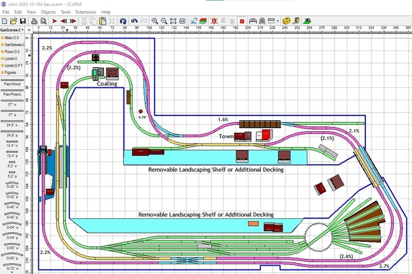
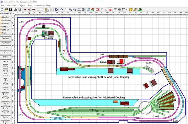
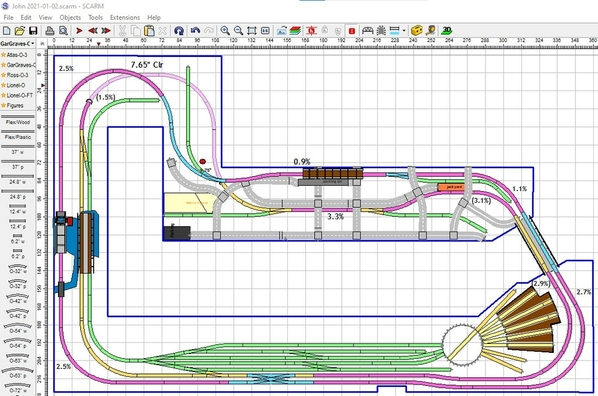
I have moved the crossover to the start of the straight runs, incorporated a double track bridge (which I'll have to find one to fit) Not sure what , if anything stills needs to be done to the yard. Thoughts everyone?
John,
This is absolutely just my personal opinion with no experience to back it up, but you’ve already bought the double-crossover, so I think you should use it. I think it’s overkill in the yard and should be put back where it was. However, it should NOT be moved to the curves. The reason it was to the right of the crossover that goes to/from the yard is so trains can either go from the outer main directly into the yard or those coming out of the yard can go directly to the outer main. Putting it anywhere else just doesn’t make sense. If you put it where you did, you raise the grade going left and lower the grades going right, just a simple exchange. However, trains have to go all the way around the layout to use it. You can still add a crossover in the yard, but you’ll only need 2 switches for that, not 4.
The bridge you added on the bottom makes no sense. The mains are too close to have any reason for 1 bridge there. It could make sense along the purple straight section in the town.
Adding another double bridge across the river makes sense as does adding a 2nd removable shelf for the town.
Dave, IMHO you make lots of sense, with suggestions and opinions. I agree on the over kill in yard with the cross over. It would be nice to use, however I could always sell it on e-bay or here. I was messing with you, putting the bridge at a random spot. ![]() I'll make some more changes as we seem to be thinking along the same lines. I am tending to keep the double crossover for the very reason Mark stated, it helps a small layout. Not sure the best place to put switches in place of the crossover in the yard.
I'll make some more changes as we seem to be thinking along the same lines. I am tending to keep the double crossover for the very reason Mark stated, it helps a small layout. Not sure the best place to put switches in place of the crossover in the yard.
On other notes, the long main lines straight away against the wall, I am envisioning two different grades for those tracks. The one closest to the wall should be the higher track of the two until they meet near the entry bridge. I hope there is enough space between them to have a hillside or rock cliff between the two lines. (Leaning toward rocky cliff) Any opinions??? All are welcome.
Attachments
Looks good and possibly we are nearing the final phase. Again Thanks for ALL the help and support.
Ok, it's up to you to decide which is more important; access to the double-crossover or different elevations leading up to the dual track bridge.
Attachments
Yes, back out on the mainline is the place for it. I agree, Dave has given the pros and cons of placement of it on that straightaway. I do agree it seems you are getting very close. Once you are building, you will come up with other things. Some things are changes because it doesn't quite work out in three dimensions, you will think of something better, or you goof something up and don't realize it for a while where you have to decide whether to go back and change it, or change things to match up with the goof up. All of those situations happened to me! ![]()
@DoubleDAZ posted:
I like this version a lot and will start playing with elevations for the town etc. Again thanks for all the help from you and everyone else!
Merry Christmas to all !
Merry Christmas, John!
Merry Christmas to all
Merry Christmas everyone.
Santa was very kind and generous to me this year. There under the tree was a topside creeper Traxion model 3-100. Which I put together today and tried it out for reach and comfort. I have to admit it may take some getting use to leaning on, however it gives me an easy 4 foot reach, which is what I was hoping to get. ![]() Thank you Santa!
Thank you Santa! ![]()
Santa is old enough to know the value of such a gift. 
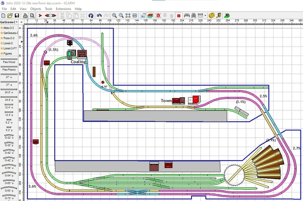
Hello All, I tried my best to keep Main line on the straight line of switch vs the turnout. and I straightened out the track that went through town. moved the two spurs to accommodate the main lines. Let me know if this was an improvement or did I mess something up inadvertently?
Thanks as Always!
Attachments
John,
I spent some time trying to figure out some of the changes and fixing the TT/RH. For some reason you ended up with an 8.3% grade where the tracks on the left meet the tracks curving to the top. Fixing that forced other changes to maintain adequate separation where the curves overlap. I don't know if I figured things out close to the way you wanted them or not, you can decide.
The TT/RH is a different story. You can't just copy/paste parts of the RH and use flex track to make things look like they fit. The tracks coming off the TT going into the RH are at 9° while the others are at 10°. And I'm not even sure at this point if the whiskers are far enough from the outside walls of the RH, they might need to be 11° or 12°.
You also don't really want to add long tracks just because they fit. You only need tracks that are long enough so engines clear each other when moving to/from the TT. At this point I really don't know how long those 3 whiskers need to be, but they only need to hold engines that fit on the TT. If you want to waste track to fill the same, that's fine, just FYI.
I'm not exactly sure why, but you obviously want that bottom yard track to be as long as it can be, so I left it off the TT like you had it. You can still access the long stalls in the RH, so no problem making it as long as you want.
Basically, I like the changes you made. In fact, if you notice, the Orange/Yellow tracks are now flat past the switch, so you can make the town stretch to the left more. Each change gets you closed to a final design, at least in SCARM. ![]()
Attachments
@DoubleDAZ posted:John,
I spent some time trying to figure out some of the changes and fixing the TT/RH. For some reason you ended up with an 8.3% grade where the tracks on the left meet the tracks curving to the top. Fixing that forced other changes to maintain adequate separation where the curves overlap. I don't know if I figured things out close to the way you wanted them or not, you can decide.
Sorry I did not checks grades again, just too excited that things are working out better and better. I trust your judgement for sure.
The TT/RH is a different story. You can't just copy/paste parts of the RH and use flex track to make things look like they fit. The tracks coming off the TT going into the RH are at 9° while the others are at 10°. And I'm not even sure at this point if the whiskers are far enough from the outside walls of the RH, they might need to be 11° or 12°.
You are totally correct about TT/RH and the angles. Thanks for cleaning that up along with your other chages. My thought was the space was adequate for the combo tt/RH Using an index tt should be able to be programmed for the correct angles. There is still some wiggle room to make corrections while building. Let me know if my thought was out of the ballpark.
You also don't really want to add long tracks just because they fit. You only need tracks that are long enough so engines clear each other when moving to/from the TT. At this point I really don't know how long those 3 whiskers need to be, but they only need to hold engines that fit on the TT. If you want to waste track to fill the same, that's fine, just FYI.
Another good point! I'll adjust to your recommendations
I'm not exactly sure why, but you obviously want that bottom yard track to be as long as it can be, so I left it off the TT like you had it. You can still access the long stalls in the RH, so no problem making it as long as you want.
no need for that either, and I am not sure flextrack would bend to the TT as sharp as I currently have it
Basically, I like the changes you made. In fact, if you notice, the Orange/Yellow tracks are now flat past the switch, so you can make the town stretch to the left more. Each change gets you closed to a final design, at least in SCARM.
Here's
Main objective was to get the main line off the turnout and on the straight part of the switch. You are too kind with your comments. Thanks!
Attachments
John, The first attempt looks great! Mark that day down on a calendar. Seeing the topside creeper, how do you think it will work out for you?
@Mark Boyce posted:John, The first attempt looks great! Mark that day down on a calendar. Seeing the topside creeper, how do you think it will work out for you?
Thanks... and the creeper will be awkward for sure, however it makes the 4 foot width possible without too many hassles. I was up on it simulating working height, and it will get tiring working for a long period like that, so it will be used, however it will not be the main mode of work. I am still going to use the removable shelves, for everyday operations and maintenance. Plus do as much far reaching work before table top is completed. Thinking on two, 2-foot sections one against wall and the other next to isle. Not putting isle in until I have to, so background can be done. I am hoping to do some painting and possibly a couple of commercial backgrounds for the city/town area which would be wayyyy beyond the scope of my artistic abilities. LOL My wife will be called to duty with the art work. Not sure how to make a road "dissappear" into the backdrop before that scenery and track work is done. It would be great if I could get the 2 foot wall section done then paint background. I know my wife would not like the creeper and I am artistically challenged.
Also Mark I think the bench work is too high and I will need to cut it down. Not a big deal as it is just screwed together. It is at 40.25 inches at the top of the joists. Add either plywood, homosote and roadbed or plywood, foam and road bed, that is an added inch then track elevations go up to 52", that seems to big a bit tall for my wife. What are your layout heights? And do you like then? Also I have concerns the draw bridge is 40" and track at that area is 50" so I need 90" + inches (7.5 feet) for clearance when in the upright position.
I am reading a lot on the various methods for track work, roadbed and surfaces. Homosote and foam seem to be the two top contenders. Any thoughts from you and everyone else?
John, the bench work looks nice. One suggestion is that when you get to the TT/RH area, make the stringers longer than you have in the design in case the decking needs to be a bit larger than shown. I’m still concerned about how large the RH actually is and the angles of the outside whiskers. I know the TT indexes, but I’d hate to see you resort to flex track coming off the TT to make things fit. You can always trim the stringers and decking, a lot harder to add, though you can sister in extensions. As you said there’s wiggle room during the build, just trying to make sure there’s enough.
When it comes to whiskers, don’t get me wrong, there’s nothing wrong with using a 37” track even if it’s too long, just didn’t want to see you add extra track just to fill the space. You need room for trees and such when adding landscaping. And the closer you index, the longer the whiskers will need to be for clearance near the front where engines will pass each other. Wider indexing lets you use shorter tracks, but makes the overall footprint larger in width.
I actually thought my comments were a little harsh, especially about the TT/RH. The TT/RH are a bit of a sore spot for me because it took a long time to figure things out in another design I’ve been working of for someone else and I’m still not confident I know how things will work out. I’d be fine if it were my layout, but it’s tough when it’s someone else’s. If I make a mistake with my own design, I can deal with it. But, if I make one with yours, you have to deal with it and that’s a bit unsettling for me, especially since we’re trying to cram stuff in tight spaces.
One thing I keep forgetting is that I also have the RR-Track software with some accessory libraries, so I can get footprints for a lot of buildings, etc. Unfortunately, that doesn’t include roundhouses and I haven’t looked to see how much detail I can get from the objects. Still, I should see sometime how hard it would be to convert some to SCARM, even though creating 3D objects in 2D is a tedious process because everything has to be done in layers or parts cover other parts making editing really difficult.
Anyway, the final comment is to really plan out the track laying process. I’m working on a 15’x30’ 4-level connected design with another member. Major parts of each level are the same, so to make sure things will fit as designed, he’s taken the trouble to lay one level of track on the floor, complete with power to run a train, before he’s even started the bench work. And, he’s doing it within the limitations of tubular track. A lot of folks lay out all the track before tacking anything down, though I suppose that’s harder to do with elevation changes and cookie-cutter style bench work. The hardest sections are those that include custom cut tracks. You can’t rely on the software to give you exact lengths, so you need to take extra care when laying things out before you cut. I’m sure Mark and others have plenty to say about that.
Hi Dave, Totally understand the TT/RH issue/s that I create. I will heed your advice on cutting long then trimming when it all fits. Also I agree on the whisker tracks being shorter, I cut them down to 30" and may go to 28" as a 27"TT will not handle a 30" engine...![]() I again appreciate your "harsh" comments as they bring the point home. You do great work and take pride in your work, which is btw totally outstanding. I was considering putting track together on the floor, which at my age and height is not easy, but I can see yours and others points for fit. My thought is the benchwork is only critical around TT/RH. The rest is pretty much the max size I can deal with reasonably. So if I oversize the TT/RH area that maybe a good starting point to lay track on top. I wouldn't consider making any other area larger if track does not fit, so the track plan would need altering if there are clearance issues. Are these thinking errors on my part?
I again appreciate your "harsh" comments as they bring the point home. You do great work and take pride in your work, which is btw totally outstanding. I was considering putting track together on the floor, which at my age and height is not easy, but I can see yours and others points for fit. My thought is the benchwork is only critical around TT/RH. The rest is pretty much the max size I can deal with reasonably. So if I oversize the TT/RH area that maybe a good starting point to lay track on top. I wouldn't consider making any other area larger if track does not fit, so the track plan would need altering if there are clearance issues. Are these thinking errors on my part?
John, how high is the ceiling? A standard table is around 30” and I believe you’re at 32.5” to the bottom of the girder (40.25-3.5 joist-4.25 girder), don’t forget about getting underneath. Since there is nothing in the way of the entry, no door, no wall, etc., have you considered a swing-out bridge? I can envision one end being attached to a circular board attached to a 6”-12” lazy susan, like those on Amazon, that would then turn like the TT. You’d have to cut the lead tracks along the circle so they’d meet just like the leads to a TT. Another option would be a simple hinged base. You’d also need a support for the other end, but that could be as simple as a large dowel with a wheel on the bottom. Since the bridge only weights about 6 lbs, you could also do a lift-out.
John, you have to allow room at the TT end for engines to pass, so I think 28” will be cutting it too close for engines that just barely fit on the TT. You can see the tracks going into the RH at 9° are closer to each other than the outside whiskers at 10°. That’s because engines will be parked further from the TT in the RH until they’re back in service. The larger the degree, those closer engines can be parked to the TT and the shorter the whiskers need to be. BTW, I made the whiskers 10° only because I don’t know if they’ll hit the RH at 9°. That’s something you can decide during the install. Just remember that the smaller the degree, the longer the whiskers needs to be, bit it looks like there is plants of space for your needs.
John, The top of the cork roadbed on the table is 43 1/2" high. The top of the highest point is 50" It works here, but my layout is only 30" deep. My table and level upper level is 1/2" or 5/8"plywood/pressed furniture wood, then 1/2" Homasote, then O scale 1/4" cork to give the tapered roadbed look. It can total 1 3/8" total. I only used the foam for the grades because I couldn't figure out how to make the cookie cutter work in this case, partly because of what Dave mentioned and partly because I don't have access to better tools and skills. The foam still has Homasote and cork on top of it.
I think with your layout having deeper shelves, you may be right about lowering what you have a few inches, especially concerning your wife's height. Also, if you do make the bridge lift up, you will need the extra height as you mentioned. My bridges will only span 26", so it isn't a problem even though my ceiling is only 7' 4" high. I'm working on an arrangement like Mike G. did. Dave is right, a swing out arrangement may be better for you, although that has it's challenges too. Myles (Trainman2001) did one of those and described it at length in the early pages (maybe 5 years ago) of his Continuing Saga... topic. I didn't want to do one like that because I have very little room to swing it out without putting me through the sliding glass door! ![]()
@DoubleDAZ posted:John, how high is the ceiling? A standard table is around 30” and I believe you’re at 32.5” to the bottom of the girder (40.25-3.5 joist-4.25 girder), don’t forget about getting underneath. Since there is nothing in the way of the entry, no door, no wall, etc., have you considered a swing-out bridge? I can envision one end being attached to a circular board attached to a 6”-12” lazy susan, like those on Amazon, that would then turn like the TT. You’d have to cut the lead tracks along the circle so they’d meet just like the leads to a TT. Another option would be a simple hinged base. You’d also need a support for the other end, but that could be as simple as a large dowel with a wheel on the bottom. Since the bridge only weights about 6 lbs, you could also do a lift-out.
Hi Dave, The ceiling is at 93" , however there is a steel beam in that area that is only 8 4" from the floor. I will check in morning to see if it will be over th bridge. Without checking, I would say it won't interfere . Swing bridge is an option for sure.
@DoubleDAZ posted:John, you have to allow room at the TT end for engines to pass, so I think 28” will be cutting it too close for engines that just barely fit on the TT. You can see the tracks going into the RH at 9° are closer to each other than the outside whiskers at 10°. That’s because engines will be parked further from the TT in the RH until they’re back in service. The larger the degree, those closer engines can be parked to the TT and the shorter the whiskers need to be. BTW, I made the whiskers 10° only because I don’t know if they’ll hit the RH at 9°. That’s something you can decide during the install. Just remember that the smaller the degree, the longer the whiskers needs to be, bit it looks like there is plants of space for your needs.
Dave, these are things that I never think of, but demand consideration. I'll keep whiskers at 29-30 inch range. And dealing with the RH tracks and engines interfering with each other at the TT is a definite issue. I read someplace the ties may need cutting to put tracks adjoining on the TT meeting point.
@Mark Boyce posted:John, The top of the cork roadbed on the table is 43 1/2" high. The top of the highest point is 50" It works here, but my layout is only 30" deep. My table and level upper level is 1/2" or 5/8"plywood/pressed furniture wood, then 1/2" Homasote, then O scale 1/4" cork to give the tapered roadbed look. It can total 1 3/8" total. I only used the foam for the grades because I couldn't figure out how to make the cookie cutter work in this case, partly because of what Dave mentioned and partly because I don't have access to better tools and skills. The foam still has Homasote and cork on top of it.
I think with your layout having deeper shelves, you may be right about lowering what you have a few inches, especially concerning your wife's height. Also, if you do make the bridge lift up, you will need the extra height as you mentioned. My bridges will only span 26", so it isn't a problem even though my ceiling is only 7' 4" high. I'm working on an arrangement like Mike G. did. Dave is right, a swing out arrangement may be better for you, although that has it's challenges too. Myles (Trainman2001) did one of those and described it at length in the early pages (maybe 5 years ago) of his Continuing Saga... topic. I didn't want to do one like that because I have very little room to swing it outwithout putting me through the sliding glass door!
Mark, Thanks for your height info.,and recommendations. I will lower it and see how that looks. Using 2x6's and standing on those will give me a good idea at the lower height. Also how loud or muffled are your trains on the plywood homosote cork bedding? Thanks in advance
John, yes, ties will need to be trimmed at the TT. Tom Tee and Mike_CT can probably offer some advice on how best to do that.
John, I can run my MTH engines at a sound level of even 20% and still not hear any track noise except the clickety clack of wheels going over rail joints, which is music to my ears. It is nothing like the constant rumble of a train going over Fastrak on my Christmas setup.
Thanks for the positive feedback Mark. Now here I o messing around with a good layout... I think the only changes I made were in the Town area and the track going to the dog leg. My goal was to get a main street for the town with buildings so the main lines were separated to accommodate this goal. Mark, Dave and everyone else, let me know your thoughts on this version. I believe I have elevations correct and grades a little higher but not much, at least I hope. 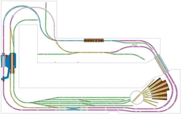

Attachments
John,
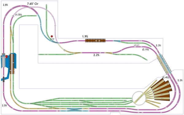
I fixed the color coding so you'll know where your grades are and updated the percentages. There are grades past the parking lot on mainline1 (0.9%) and through the town on mainline 2 (3.3%) that weren't obvious by the color.
There was room in the upper left corner, so I added some tracks to the mainline1 grade there to lower it from 3.0 to 2.5% and noted the spacing of 7.65".
Your junk yard equates to only 6x24 yds and the curved part of the spur is too close to the tracks. The spur is at 51" and the yard is at 46.25", so I assume the yard and road are on a hill. Scale cars are around 4.25"x1.75", so you have room for 4, or 8-12 if you stack wrecks.
Conversely, some mobile homes are just over 7"x2", so the mobile home park can contain enough to make it look right.
I think you forgot about the pole at the corner of the upper left nook because the curve and spur there look too close to it. I moved it from the Baseboard layer to the Mainline1 layer so it won't be overlooked. I fiddled with it so you could see what direction to take.
The roads through town will have to deal with grades, so getting them to look right might be a bit challenging.
Attachments
It would be a challenge, but a neat looking town with the grades. Actually probably less grades than the part of Butler that we go through entering town from several directions including where our older daughter's house is. I think it is good to have some ideas of what your scenery will look like, but what you actually will do will change as you are building. The junk yard spur can be a bit of a problem, but if you ret rid of the curved part, you could just have miscelaneous junk and not items as large as cars.
@DoubleDAZ posted:John,
I fixed the color coding so you'll know where your grades are and updated the percentages. There are grades past the parking lot on mainline1 (0.9%) and through the town on mainline 2 (3.3%) that weren't obvious by the color.
This is how little I know about layout planning. I did not realize there was a color code? Does a color signify a certain grade? What do you use?
There was room in the upper left corner, so I added some tracks to the mainline1 grade there to lower it from 3.0 to 2.5% and noted the spacing of 7.65". Thanks!
Your junk yard equates to only 6x24 yds and the curved part of the spur is too close to the tracks. The spur is at 51" and the yard is at 46.25", so I assume the yard and road are on a hill. Scale cars are around 4.25"x1.75", so you have room for 4, or 8-12 if you stack wrecks. I was hoping for a general scrap yard with gantry crane, however that doesn't sound possible at that area.
Conversely, some mobile homes are just over 7"x2", so the mobile home park can contain enough to make it look right.
I think you forgot about the pole at the corner of the upper left nook because the curve and spur there look too close to it. I moved it from the Baseboard layer to the Mainline1 layer so it won't be overlooked. I fiddled with it so you could see what direction to take. Pole is measured 9.75" x 2" from walls, I didn't forget, just turned a blind eye, hoping it would go away!
The roads through town will have to deal with grades, so getting them to look right might be a bit challenging. Roads maybe a bit challenging, however they are easier to deal with than track grades. Hoping I am up for the challenge.
Again Dave, Many Thanks for your eye to detail and doing things correct. That is priceless!
@Mark Boyce posted:It would be a challenge, but a neat looking town with the grades. Actually probably less grades than the part of Butler that we go through entering town from several directions including where our older daughter's house is. I think it is good to have some ideas of what your scenery will look like, but what you actually will do will change as you are building. The junk yard spur can be a bit of a problem, but if you ret rid of the curved part, you could just have miscelaneous junk and not items as large as cars.
I am hoping I can deal successfully with the grades and the town comes out ok. And I am sure some things will change as I get things going and realize what I forgot or never thought of! ![]() I should have called it a scrap yard so cars would not consume the space. Thanks Mark for your help and support.
I should have called it a scrap yard so cars would not consume the space. Thanks Mark for your help and support.
John, the color-coding is mine. It helps me identify different sections, like grades (purple), mainline1 (blue), mainline2 (orange), yard (green), etc. It also lets me select a section of tracks simply be double-clicking on 1 track in the section, particularly when trying to create grades. I select a purple section, then add or subtract tracks to see how the grade changes.
The footprint for Lionel’s Gantry Crane in RR-Track is 5.5x11.5”, so it will not fit where the junk yard is if that’s the one you’re considering.
I went back to a final room dimensions file from 2020-08-28 where you indicated the pole was 12” from the wall and 3” up from the corner, though you didn’t say how round it was. It stayed that way until file 2020-11-25 when it was shrunk from over 6” round to 3.25” round and the edge was placed 9.75” from the side wall and 3” up from the corner. Now you’re saying it’s 2” up from the corner, but still 9.75” in from the side wall, is that correct?
Attachments
@DoubleDAZ posted:John, the color-coding is mine. It helps me identify different sections, like grades (purple), mainline1 (blue), mainline2 (orange), yard (green), etc. It also lets me select a section of tracks simply be double-clicking on 1 track in the section, particularly when trying to create grades. I select a purple section, then add or subtract tracks to see how the grade changes. Yes the color coding helps a ton for sure. I did not know if there was a scarm standard, should have realized that was your helpful addition.
The footprint for Lionel’s Gantry Crane in RR-Track is 5.5x11.5”, so it will not fit where the junk yard is if that’s the one you’re considering.
Yes it was, but should fit in somewhere else....
I went back to a final room dimensions file from 2020-08-28 where you indicated the pole was 12” from the wall and 3” up from the corner, though you didn’t say how round it was. It stayed that way until file 2020-11-25 when it was shrunk from over 6” round to 3.25” round and the edge was placed 9.75” from the side wall and 3” up from the corner. Now you’re saying it’s 2” up from the corner, but still 9.75” in from the side wall, is that correct?
Dave, what you have drawn below here is 100% accurate! Not sure how I will hide this HUGE Chimney! LOL I also played around with some of the grades and here is what I came up with to ease the grade on the short town track. Basically lowered the entry/lift bridge to 49" Let me know your thoughts, Thanks
Attachments
John, there aren't any SCARM standards for that sort of thing. I used to place grades on separate layers before I discovered that color-coded sections could be selected with a double-click. I still put them on layers when I need to be able to hide them while editing for some reason. When you do as much editing as I do, these little tricks can really speed up the process and keep me straight. Coloring is pretty much the first thing I do when someone sends me a layout or I download one from the forum.
What are your plans for the spur going up into the nook? Looks like a perfect place for a gantry crane operation of some sort, just a thought.
As far as the pole is concerned, I had it as 84". However, since much of it will be hidden by a hill, why not turn it into a water tower. I separated it into 3 parts; the bottom, the reservoir and the top (could be painted the same color as the walls). Or you could add another in the back left corner and add a Zip Line into a small forest. Instead of a gantry crane, you could add a Ferris Wheel and other carnival accessories, though I like the junk yard with crane.
Attachments
Hi Dave, I do see the advantage to color coding for selection of tracks for elevations etc. Do you have a color code like yellow is < 1% grade Purple is 1% to 2% grade Yellow is 2% to 3% grade orange is 3% to 4% grade? Spur going up the nook could be junk yard / Gantry crane area, did not have that thought out yet. Good suggestion. Also another good suggestion on the pole painting the higher portion the same as the background. Intuitively I feel there are lack of crossovers / tunnels, I was going to work on the town area and roads before messing up a really good track layout.
Again Thanks for all the help.
John


