@gunrunnerjohn

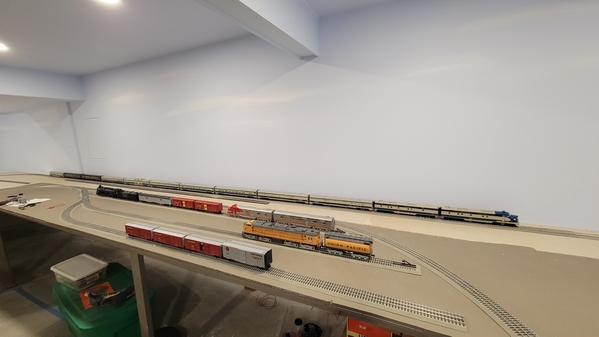
I have a very odd situation. I am building a new basement layout and decided to put a temporary O96 Fastrack dog bone with 3 O72 switches creating a 3 leg staging ladder. Power supply is a 180 W brick controlled by a Legacy Powermaster. I have a Legacy base and several LCS devices daisy chained driven off the DB9 cable/PDI cable(s). The ground/signal wire from the base goes into a ground bus. From that bus I soldered a wire to the bottom  side of the outside rail of a piece of fastrack. The dog bone spans the width of the room approximately 30'. I soldered several hot and ground wires and dropped them down to the corresponding buses under the benchwork. The Legacy base is mounted about 9' off the ground in a central location.

PROBLEM: I have a couple Vision Line stock cars. One of them will NOT respond to commands on the O96 layout. Also, on occasion various engines will blow the whistle WITHOUT the command being input to the CAB2.

When I completely power down the O96 layout (on a dedicated 20 AMP circuit) and take the very same car to my workbench which has its own Legacy Base and a test track powered by a 80W transformer the stock car DOES respond to commands. So the car works.

I have some kind of signal issue on the temporary layout. I have swapped bases...no effect. I have traced all ground wires, not one is tied to the wrong bus. I swapped out the DB9 cable....nothing. I am out of ideas and am coming to the forum for help. There are many members far smarter than I here and I am hoping someone can point me in the right direction.

thanks for any suggestions!

Original Post

Replies sorted oldest to newest

You may have a TMCC ground plane issue.  You mention "ladder" which implies elevated tracks.  The signal emanating from overhead tracks can interfere with the signal detected on tracks underneath.  There are numerous threads on the forum resolving the ground plane issue but a simple experiment to try is run a 3-wire extension cord, plugged into the grounded circuit that powers the base, along the track where the signal appears weak.  If that resolves the problem, review the ground plane threads for a better solution.

@T4TT posted:

@gunrunnerjohn

I have a very odd situation. I am building a new basement layout and decided to put a temporary O96 Fastrack dog bone with 3 O72 switches creating a 3 leg staging ladder. Power supply is a 180 W brick controlled by a Legacy Powermaster. I have a Legacy base and several LCS devices daisy chained driven off the DB9 cable/PDI cable(s). The ground/signal wire from the base goes into a ground bus. From that bus I soldered a wire to the bottom  side of the outside rail of a piece of fastrack. The dog bone spans the width of the room approximately 30'. I soldered several hot and ground wires and dropped them down to the corresponding buses under the benchwork. The Legacy base is mounted about 9' off the ground in a central location.

PROBLEM: I have a couple Vision Line stock cars. One of them will NOT respond to commands on the O96 layout. Also, on occasion various engines will blow the whistle WITHOUT the command being input to the CAB2.

When I completely power down the O96 layout (on a dedicated 20 AMP circuit) and take the very same car to my workbench which has its own Legacy Base and a test track powered by a 80W transformer the stock car DOES respond to commands. So the car works.

I have some kind of signal issue on the temporary layout. I have swapped bases...no effect. I have traced all ground wires, not one is tied to the wrong bus. I swapped out the DB9 cable....nothing. I am out of ideas and am coming to the forum for help. There are many members far smarter than I here and I am hoping someone can point me in the right direction.

First we must correct some terminology or else we are going to have one heck of a time trying to get you to troubleshoot this.

The transformers we use in model trains are isolation transformers. The output is completely 100% isolated and not connected to earth ground or the AC neutral coming into the transformer from the wall. Also, we build the track often on wooden insulating tables.  The key point is- NOTHING of the track or wiring in general of a layout is true earth "ground". You should avoid using that term to prevent confusion. I try to use the word "Common"- and since this is labeled on many devices- all outside rail of your track, that bus wiring, and the "U" terminal of the transformer is "common".

TMCC or Legacy radio signal is created by the base because the one exception here- the power supply for the base must be plugged into a grounded outlet (3 prong) and this connects the base internal electronics through it's specific and special power supply to earth ground and wiring of your house. The transmit post of the base is connected to common aka "U" and the outside rail of the entire track to form one side of the antenna. Now the important part- the rest of the wiring in your house with earth ground forms the other half of the antenna system for the base to transmit the TMCC signal. Edit- again, they key here, the base is connected to earth ground and all the earth ground wiring inside the walls and structure of your house via the special power supply for the base. It is then creating a radio signal difference- between that earth ground and the U AKA Common post, then connected to the outer rail of your entire layout. So the signal is the difference between your entire layout and wiring, and earth ground wiring inside your house.

Now, the kicker- get ready for upside down and inside out thinking. Your train sits on the track connected to outside rail, connected via common and your bus wiring to the base transmit post. The trains and TMCC action cars all have an antenna placed inside the shell isolated from the frame of the car- because the frame of the car is electrically connected to the wheels in most cases, to outside rail. But you say wait- you just said that the transmit post of the base is connected to outside rail, thus the entire frame of the car is also common at outside rail potential- but what is the antenna receiving?? Again, this is the kicker- ground- true earth ground. The antenna is coupling to all of the ground wiring in your house.

What you have to understand is that the TMCC/Legacy radio receivers are measuring the DIFFERENCE- the difference between 2 potentials- the frame and wheels common- and the difference between that and the antenna coupled to EARTH GROUND.

This is why others mentioned- one test is placing a 3 wire grounded extension cord plugged into a grounded 3 prong outlet, and you run that near or overhead the problem area of your table where TMCC/Legacy reception was a problem. This is what extending the ground plane means- you are placing earth grounded wires or metal and that compared to the common U of the track (which is NOT earth grounded, instead it is isolated by your transformer and the insulating table material, and ONLY connected to the transmit post of the TMCC/Legacy base).

So from all this:

  1. Ensure the correct power supply is used with your base that came with it and is in fact plugged into an earth grounded outlet.
  2. Check extension cords or power strips- they can affect this earth ground situation to the base power supply and thus prevent proper earth grounding of the base- seriously affecting transmit and reception of engines and cars.
  3. Consider placing an earth grounded wire above or near the table and areas -can be an earth grounded extension cord plugged into a 3 prong grounded outlet
  4. Another test- placing your hand just above but not touching a car or engine that has a TMCC radio reception issue. Your body being made mostly of water acts as a huge ground plane. Remember, the train is trying to receive the difference in potential- between the track outer rails and entire metal frame of the engine- and the antenna coupling to earth ground- or your hand.
Last edited by Vernon Barry

First thanks for the comments.

Here is the temporary dog bone loop......,

Temp Loop 1

Temp Loop 2Temp Loop 3

When I used the term "ladder" I was referring to the mini-yard created by the 3 O72 switches. All the track is on the same level.

The legacy base is plugged into an earth grounded outlet.

Earth Grounded Outlet

Here is the my power center...
Power Central

The 180 bricks are plugged into power strips that are then plugged into a dedicated switched 20 amp circuit (grey switch). I used 12-2 with a ground for that circuit. The 80W transformers are on a dedicated switched 15 amp circuit that continues into the train room with several outlets under the benchwork (almond switch and almond outlets).  I wired a third 15 amp circuit around the train room composed of white outlets that are always hot. I also dropped an earth ground wire from the breaker box to an open data box that I planned on running above the level of benchwork currently pictured. Over time I intend to build a second level on top of the existing level.

ground plane

I am going to remove the command wire from the common U bus and go directly to an outside rail. If that does not work I will unplug the transformer from the power strip. I have a lot of work to do before my train room is finished. I did a lot of planning and I bothered by this issue. I hope it is something simple. The wiring is all up to code.

thanks again for the advice!

Attachments

Images (6)
  • Earth Grounded Outlet
  • Temp Loop 1
  • Temp Loop 2
  • Temp Loop 3
  • Power Central
  • ground plane

Hello Marty,
Yes, the base at my work bench is on a power strip that I power down when i am operating in the train room. I named each base so i know which base I am communicating with too.

I plugged the brick directly into the wall outlet....No change.

I removed the command signal wire from the U common terminal block and soldered it directly to the underside of the outside rail of the fastrack...No change.

Whether I am seated at my work bench or 20 feet away in the train room the stock car responds to commands when on the work bench. But still refuses to respond to commands while on the temporary fastrck dog bone loop.

I removed the shell to make sure the antennae was plugged into the board. It was. In this pic you can see the antennae wire with eyelet that screws to the metal plate in the roof. There is a second, shorter black wire protruding from the board mounted vertically from the floor. That wire is just hanging out there and I don't know if it should be connected to something???

When I put the open car on the temp. loop and hold the antennae wire it still does not accept commands.

I am at a loss.

stock car

Attachments

Images (1)
  • stock car

@MartyE

Well I remain confused! I did swap the bases. When I controlled the temporary loop with the Work Bench Base the car (sans body) did not respond to commands. I took the car to the work bench, turned off the base in the train room and turned on the train room base connected to the bench test track and the car responded to commands from the CAB2! So I can say that the issue is not in either base! There has to be an issue with the wiring in the train room BUT no other car or engine has demonstrated the same behavior. I am absolutely stumped.

I am on a losing streak! I opened a NIB Lionel Lighthouse the dang LED in the rotating beacon did not come on. I keep telling myself this is a fun hobby

This will sound odd, but turn off all your train room lighting and see if you are dealing with an interference issue.  When we first installed solid state ballasts in our shop lighting, we found out none of our TV remotes would work because the lamps were now flashing at a 25Khz or so rate instead of 60Hz, and messing up the signal to the TV which was modulated at a 25Khz rate.  LED, CFL, florescent lamps are all flickering, you just cant see it, and at the same time making various amounts of RFI.  Also, does the bad car not work at all in the train room, or only in specific places on the layout?

If you're only having the problem with one car, have you taken it apart to check the antenna connection?  Do those cars have programming settings, toggle switches, or jumpers?  Most of us have one or two pieces of equipment that are divas, that won't work unless everything is perfect.

If everything is perfect with the car, I would disconnect all TMCC equipment from your stub layout EXCEPT a known good base.  Test.  Assuming that it works with just the base, gradually add your LCS components, etc., into the wiring mix, and retest after adding each component.  Eventually you'll find out what, if anything is killing the signal.  Good luck and let us know what you find!

Last edited by Ted S

Thanks again for all the suggestions. I have tried everything mentioned. With the shell off the car did respond to commands IF my hand is over top of it, BUT I cycled power off/on about 5 or 6 times to test/confirm and the car ONLY responded two times. So Vernon, your test...

Another test- placing your hand just above but not touching a car or engine that has a TMCC radio reception issue. Your body being made mostly of water acts as a huge ground plane. Remember, the train is trying to receive the difference in potential- between the track outer rails and entire metal frame of the engine- and the antenna coupling to earth ground- or your hand.

...proves that for whatever reason this ONE car has a ground plane issue that sporadically interferes with commands. I am struggling to understand why this car and not any other car, including a UP VL stock car, presumably identical in every way except the shell, work.

When I wired the room I dropped a bare ground wire from the ground bar in the breaker box through a data box in the wall. I ran that Earth ground wire up the benchwork and over the car BUT it did NOT respond to commands.

I am also at a loss on how to improve this car's ability to overcome the ground plane issue. Would a bigger metal plate antennae help?

Thanks again to all

I surrender. I soldered a wire to the metal plate that the antennae terminates on and wrapped about 24" of wire around the top of the shell. I put the car on the temporary O96 loop and it still did not respond to commands. I shut the train room down and went to the bench in the back shop and the car did respond to commands. I am ready to give up.

I re-read John's advice and I took it literally, so I removed the square metal plate and the additional jacketed wire I soldered to it and replaced it with a bare 14 gauge wire soldered directly to the OEM antennae wires. As you can see the car responds to commands on the workbench. Regardless of the version of the antenna (OEM, metal plate with additional jacketed wire or bare wire soldered directly to OEM antennae wires) the car has always responded to commands while on the bench.


@gunrunnerjohn

Last edited by T4TT

As you can see the Legacy Powermaster, the LCS BPC2, the UP VL stock car and the UP caboose all respond to commands. The only car that does not is the ATSF VL stock car, regardless of the antennae configuration. Up until this point the car consistently made the wheel flange noise and random hog squeal when it rolled. Once I pressed down on the car it did, my guess is not enough weight to complete the common "U" circuit. But on the bench when rolled it made the sounds. It does not seem like it is the board, but what could it be? Is there a way to read the signal the antennae is receiving? I only have a mulitmeter.

thanks

If it's not the antenna configuration, the obvious next likely choice is the RCDR that receives the TMCC signal.  It sounds like it's having a problem with weaker signals.

Have you tried an earth ground line next to the car as a test? That would be the first thing I tried.  Just a grounded extension cord plugged into a properly grounded outlet laying next to the track as a test.

You could also swap this board with one of the working cars and see if the issue follows the board.

Attachments

Images (2)
  • mceclip0
  • mceclip1

I swapped the boards and now both cars respond to commands in both locations, train room and back shop. I have no idea why. I did not even reprogram either, I just swapped the shells so the ENG info is correct. I will play with both cars over the next couple days to ensure it was not a fluke. Thanks for all the advice, I learned quite a bit!

These things can be baffling. I worked as a school bus mechanic. Had a new bus that developed a no crank to start only in the morning. Every morning. The rest of the day it was fine. I traced it to the main module. Input went in from the key switch but nothing came out to trigger the solenoid. It was easy enough to jump every morning but someone had to be there to do it. I decided to swap the modules from another new bus. Figured the problem would now travel to the other bus. Neither ever had an issue after the swap.

@T4TT posted:

I swapped the boards and now both cars respond to commands in both locations, train room and back shop. I have no idea why. I did not even reprogram either, I just swapped the shells so the ENG info is correct. I will play with both cars over the next couple days to ensure it was not a fluke. Thanks for all the advice, I learned quite a bit!

The mysteries of electronics, welcome to the 5th dimension!

My guess is wiring positioning, a poor connection at a connector, or the phase of the moon.

When I'm faced with similar issues, I just start eliminating possibilities until there's none left, and the problem is gone.

Last edited by gunrunnerjohn

Oscilloscope? I have traced down problems with first generation TMCC remotes transmitting at 26Mhz, and I have seen the TMCC signal around 450 kHz on the track.

I would try a cheap Chinese battery operated scope, because normal scopes connect the outer ring of the BNC to earth ground thru the three conductor power cord, which might make things confusing. Small as possible, so you might be able to put it on a flatcar and roll it around, probably with the ring of the BNC to some wiper hooked up to the outer rails, and the tip on an antenna.

Add Reply

Post

OGR Publishing, Inc., 1310 Eastside Centre Ct, Suite 6, Mountain Home, AR 72653
800-980-OGRR (6477)
www.ogaugerr.com

×
×
×
×
Link copied to your clipboard.
×
×