Hello all.  

   I have finally gotten my layout up and running, but there seems to be a problem. Previously I have only operated one train or accessory at a time for test purposes, but before today, not all at once.  I have two unconnected loops of tubular powered by the A and B terminals of the KW, with U being the common. Each loop is fed through their own independent bus bars, with power drops every so often.   I also use a 1033 transformer to provide fixed 16 and 11 volts through it’s A and B terminals, with C being the common in this configuration. Turnouts, lights, and accessories are powered through their own independent 16 & 11 volt bus bars.  I have ground straps running through all bust bars, effectively connecting all of the commons of both transformers. 

  This morning I was running everything, and after about five minutes the KW started emitting a very faint white smoke and an odor reminiscent of wet beef jerky. Not a burning plastic, or rubber smell.  It never got hot, or changed its vibration characteristics. It was purchased freshly overhauled, and I thought it may just be lubrication burning off. On a hunch, I unplugged the 1033, and ran two trains at a scale highball for about a half hour. No smoke, no odor. Hmmmm... plugged the 1033 back in, and after a few minutes the odor returned.  I stopped before any smoke started.  

  My turnouts are powered by fixed 16V through a bootstrap.  They’re TinMan overhauled units, and if I’m not mistaken, provide additional center rail voltage, unlike the original Lionel fixed voltage plugs do.  I believe this is my problem.  I do see a small spark when a train goes through a turnout, and also when crossing insulated track sections that power 16V accessories. No spark when the 1033 was unplugged...

  I guess I now realize the need to phase the transformers together, where I previously thought of them as electrically “unconnected.”  Is this the case?  If so, would I use the KW’s U terminals to the 1033’s C terminals since they are the commons?  Obviously it’d be the variable A and/or B for testing the hot on the KW, but which hot should I use on the 1033, since I’m using only it’s fixed voltage posts.  Would it be easier just to disconnect the transformer’s posts that feed the bus bars, and test/phase the transformers in the traditional way that’s been so well documented?

  Any and all thoughts or ideas greatly appreciated ...

Tom


Original Post

Replies sorted oldest to newest

You do have to phase the transformers, but realize with an ungrounded two prong plug, if you flip the plug they will be out of phase again. Start by plugging them both in, then set them for the same voltage as close as possible, say 12 volts AC. Then measure the voltage between the U terminal of the 1033 and the U terminal of the KW. If they are in phase they will read close to zero volts, it out of phase they will read close to 24 volts. If out of phase flip one plug over. If they now read close to zero then paint one side of the plugs so you know which is up.

Pete

One other thing to note is that you want both transformers plugged into the same leg of your 220/240V house voltage. In layman's terms, it is best accomplished with a power strip. You never know (with out testing) if an outlet on one side of the room is on the same leg as the other unless they are on the same circuit.

Also, when pairing small single train transformers such as the 1033 with a multi-train transformer such as the KW, understand that the multi-train unit uses U for the outside rail, and the single train uses U for the center rail. Therefore, you should have the KW U terminal tied with the 1033 A terminal. That means your 1033 B-U bus can't be wired up in a common ground scenario.

Last edited by bmoran4

Well you seem to be doing everything right - the 1033 "C" is electrically equivalent to The "U"(at the full throttle setting) without involving the wiper circuit.

So, setting the KW "A" to ~16 volts, connect its "U" and the 1033 "C" to your common bus. In phase, you will be close to zero volts between KW "A" & 1033 "A". If it's ~30-32 volts, flip the plug on the 1033.

Don't try to pass any extra track feeders through the Tinman switch controllers at this point. That will involve co-mingling of the KW track power with your fixed voltage buses.

Also, take an inventory of your power draw - the 1033 is only rated at 4.5-5 amps continuous. Just 20 incandescent bulbs will put you up to that level without even activating the first track switch.

ADCX Rob posted:

Well you seem to be doing everything right - the 1033 "C" is electrically equivalent to The "U"(at the full throttle setting) without involving the wiper circuit.

So, setting the KW "A" to ~16 volts, connect its "U" and the 1033 "C" to your common bus. In phase, you will be close to zero volts between KW "A" & 1033 "A". If it's ~30-32 volts, flip the plug on the 1033.

Don't try to pass any extra track feeders through the Tinman switch controllers at this point. That will involve co-mingling of the KW track power with your fixed voltage buses.

Also, take an inventory of your power draw - the 1033 is only rated at 4.5-5 amps continuous. Just 20 incandescent bulbs will put you up to that level without even activating the first track switch.

   Thanks for the tips guys...I thought I had the wiring figured out, but certainly do not. I did have an a-ha moment earlier. 

  I reread Rich’s (Tinman) instructions for his O22 controllers.  I noticed a passage about their fixed voltage plugs that I had previously thought didn’t pertain to my setup.  I knew his bootstrap (fixed voltage) plugs are modified to add power to the center rail.  But if I’m understanding correctly, this means a fixed 16v from my 1033 to power the switch (a good thing) but also 16V from the 1033 to the switch’s center rail (bad)   I can see that if a switch’s center rail power was coming from the KW, it’d be ok, but a fixed 16v from the 1033 as being bad. Doubly bad if the transformers aren’t phased. Am I on the right track with this hypothesis?  It’s as simple as disconnecting one wire from the bootstrap to remove the center rail power function, while retaining 16v accessory power for switch actuation. 

This leads me to another question...

   How is using insulated track (powered by the KW) to operate things like a banjo signal, semaphore, or switch tower affected if they’re being powered with the 1033’s fixed 16 volts?  Since it’s a grounding action that completes the circuit for actuation, and the KW common is connected to the 1033’s common, am I ok doing this?  When the KW started smoking that first time, I disconnected all of these from the 1033 & connected them to track power instead.  I do like how the banjo & semaphore operate on 16v much better, and would certainly prefer it...

Rob, it was on your good advice that I purchased the 1033, for a whopping $11. Shipping was actually more than the transformer!  Right now, I’m only using it for several LEDs, the icing station, barrel loader, etc... the 4 O22’s are all LED as well, plus their actuation.  Block & bridge signals & banjo are led equipped.  I haven’t measured it’s total draw yet, but most is a momentary item, or LED from the 11v or 16v post.  I’ll be adding a second 1033 soon (also a Rob suggestion) to power six more O22’s, and I think I’ll be way under danger zone once they’re combined.  Thoughts?


Thanks again for for the advice, and anything else you can tell me about the new questions, or anything I may have missed. 

Tom

OK, like I said, avoid trying to pass any extra track feeders through the Tinman switch controllers at this point... that will require you to delineate your power districts.
Tinman 'Bootstrap'

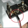
So, don't connect, to anything, whichever wire is feeding the sleeve to the track center rail - it should be the black by convention for low voltage. So that leaves you with daisy-chaining(or connecting to a 16 volt bus) the reds to the "A" post of the 1033 for a fixed 16 volts nominally with the "C" post connected to the KW "U" post(via your common ground bus).

And here is where your KW "smoke" comes into play... by connecting those black "bootstrap"(a terrible name for them) wires all together, to anything or anywhere, you have created an internal short in your KW between "A" & "B" which has no circuit breaker protection. I have not tested it on a KW, but it will be very close to my ZW testing. When you have the two levers of the KW set to different voltages, that is a direct short across the variable secondary. With the ZW, it exceeds 20-30 amps at a 6-7 volt difference in the throttle settings... the internal wiring(& often external layout wiring as well) heats up, & Voilà... smoke.

The use of those "bootstraps" is optional, but you just have to treat them as lockon connections, so your "A" post only gets connected to black switch bootstraps on your "A" powered loops, and your "B" post only gets connected to black switch bootstraps on your "B" powered loops. If you are using a Tinman dual controller that controls a switch on each loop, that just won't work as it will cause a short and you just give up that feature for that pair unless you separate the wires from the controller.

Attachments

Images (1)
  • Tinman 'Bootstrap'
Last edited by ADCX Rob

   Rob, your response clearly explains what is happening, both within the switches, and inside the KW.  Thank you!   TinMan’s own document confirms this, color code and all...”if you only want accessory power, then only attach the red lead, and forget about the black”  Wish I’d understood it sooner...

Quite glad it was something so simple!

  While I have you on the horn, do you see any problem with powering track side signals from the 1033’s 16v, but actuated by KW powered insulated rail sections?  Once the two transformers are properly phased & since they’re already mutually grounded to each other, will I still have a similar mixing of voltages or internal shorting like the switches caused?

Thanks a million.  I really appreciate it!

Tom


FlyPlanes-PlayTrains posted:

 ...do you see any problem with powering track side signals from the 1033’s 16v, but actuated by KW powered insulated rail sections?...

The insulated rail sections are not connected to or powered by either transformer, but are connected to the accessory.

Once KW "U" & 1033 "C" posts are phased and connected to the common bus, common is common. With the complete circuit operating the accessory, the outside running rails are common to the KW & 1033, electrically the same. Even though the train may be powered by the KW, the accessory will be powered by the 1033 if the non-common side is connected to 1033 "A" or "B".

In an extreme case as an example, you could use a 12 volt car battery instead of the 1033, make "-" common to the "U", and power any DC compatible accessories from "+".  All the insulated rail sections do is act in conjunction with the wheels/axles as a switch, connecting your layout common as the final link in completing a circuit. The KW would have no idea that the train it's powering is also using its wheels and axles to complete a DC powered circuit out on the layout.


Add Reply

Post

OGR Publishing, Inc., 1310 Eastside Centre Ct, Suite 6, Mountain Home, AR 72653
800-980-OGRR (6477)
www.ogaugerr.com

×
×
×
×
Link copied to your clipboard.
×
×