Hello everyone!

After many years, two Christmas layouts built when I was in high school and another in college, its finally time to build a semi-permanent layout!  My wife and I recently purchased our first home and, luckily, for me, I've secured a nice spot in our unfinished basement.

I'm still in the early planning stages, but want to use this thread as my build thread over the, realistically, years to highlight the build and layout changes. As it stands, the layout will be sized around 10x16 and take a corner of the basement.  I just started using SCARM earlier this week and have somewhat of a hang of it.  I figure with a good amount of planning, I can budget out the costs of the materials and equipment I'll need to build it.  I'm still between Fastrack and Realtrax.  I do have a small supply of Realtrax handy, but I worry about future supply when MTH finally closes its doors.  The first layout I built in SCARM (which I'll go into later in the post) is using Fastrack.

My plan is to model a Western, PA setting in the time between the Steam to Diesel transition period, although I do intend to have more modern equipment as well.  My collection is largely P&LE and Union Railroad based (my great-grand father and grand father worked for them, respectively). I also have a few PRR, B&O, Amtrak, and Western Maryland engines.  I now live next to a CSX and MARC mainline, so I do expect them to make an appearance in the future.  I want the layout to have a steel mill scene, a city/small town scene, a river as a separator, and then a small town/residential scene.  I know these are some lofty goals, but I want to work to get them to fit in.

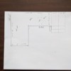
Now! For my first take of the layout and for some suggestions and help.  The first picture is largely what the roughed over view of the 10x16 layout space.  The dotted areas on the right, were originally if it were only going to be a 4ft space, but I have the ability to go 6ft.  I want to build it in modules in the event we move, or I need to move and reconfigure the layout.

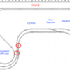
The second picture is the initial take at the layout.  I was using the free version of SCARM and ran out of pieces.  I am planning to purchase the license in the very near future.  The areas in red are my problem areas.  These are where my track isn't lining up or is close, but there are no fast track pieces to fit the gap. The long straight along the back wall will be elevated.  I'd like to run the URR loop on the left up and under it. I've also been toying with a small mountain area around the turn on the right.  Again, this isn't fully finished yet and is my first take.  I know I need to finish the URR loop, and maybe even a small yard in that area.  I'm fully open to any thoughts/ideas you all may have!

Again, I'd like any thoughts you all may have.  I know there are some amazing layout designers out there and I'm an admitted newbie, so I may be missing something and thinking too inside the box.  This has been daunting, but I'm 1) up for the challenge, 2) want to learn some new skills, 3) be able to finally build a layout that I've been dreaming about since I was a teenager, and 4) give back to the broader O-gauge community in the future from my learned experiences.

Thanks for all of your help!

-Justin

Attachments

Images (2)
  • PXL_20201121_151800558
  • Screen Shot 2020-12-06 at 7.13.00 PM: SCARM layout 1
Last edited by Tall J
Original Post

Replies sorted oldest to newest

You might want to look at a thread started by G3750 who is building the PRR Panhandle Division.  His aspirations are somewhat similar to yours.  You might also give serious consideration to using track that will still be manufactured in a few years.  Many here use Gargraves track (a lot of flex-track is used, but not by everyone) and Ross switches; some use Atlas track & switches; and many just use old fashioned tubular track and switches.  These manufacturers tend to give you more flexibility in planning because they offer more switch and complex track variations.

Next, read some threads and books on track planning.  I highly recommend Track Planning for Realistic Operations by John Armstrong (now on its 3rd edition).  There are also many other fora devoted to model railroading, most of which have a section about planning a layout somewhere therein.  Don't restrict yourself to O gauge or O scale because you will find great ideas in other scales.

Honestly, in my opinion only, you are trying to cram too much into the space you have for the time being.  Better to scale down and start like John Allen did with a masterful 4x8 oval that eventually became the heart and soul of a much bigger layout.

Chuck

PS  The trouble you report with Fastrack pieces not joining in a plan is a very common issue also dealt with in other threads here.  Many have overcome that issue, but it's work that isn't necessary with other types of track.  AND, Fastrack is very, very noisy.

Last edited by PRR1950

A few observations ...

1)  Your layout plan has a LOT of straight runs. Consider installing slight curves along the routes - Gargraves and/or Atlas Flextrack is great for that.  Gentle curves relieve "visual monotony" of long straight runs. Since the future of MTH is now unclear, their track products may (or may not) be readily available when/if you want/need them.

2)  Find an appropriate place for a double crossover; it will enable traveling from inner to outer loops in both directions.

3)  You showed a reverse loop that can reverse the direction of a train. Get creative with track planning to "hide" a reverse loop so it isn't "obvious."  Mere loops of track with trains moving in unchanging directions soon becomes boring.

4)  An upper loop could be designed with a theme; for example, an all-Christmas area with Dept 56 lighted porcelain buildings and figures. It would be a spectacle for your family and visitors at Christmas time. Some Dept 56 buildings are animated -- they seem like an "echo" of action accessories by Lionel and MTH. Fun for kids to watch!

5)  If you want to incorporate passenger service, create a "downtown depot" and a "rural station" or two so passengers have a reason to travel to/from those places.

6)  Create sidings for industrial buildings and action accessories; give your trains "work to do" just like actual RRs.

Just thinking out loud ... carry on!

Mike Mottler     LCCA 12394

Hooray! another URR fan in the MARC area! Here are a few thoughts, and comments.

1. I re-iterate what was said above about considering Gargraves. P&LE/URR means mills which also means industrial trackage. Industrial trackage is usually nor on a roadbed and often buried in asphalt/concrete/dust.

2. You would be hard pressed to find a straight tangent of track in the Mon Valley. If you did, a large steel trestle was probably involved. Curvy track rules the day

3. different railroads were often separated more by elevation than distance.

4. It was recommended above to hide reversing loops. Very true, although as "everything has a prototype" I believe there was at one point a loop at Browns Dump. (That would be the slag dump, not the current dump at the bottom that was once the great Century III mall 😥 )

5. In the "Amtrak" era, Both the Mon Valley line (PATTrain) and the Brunswick line had RDCs as part of their passenger fleet. Later they each used refurbed coaches (Former C&O and PRR respectively)  in push/pull service using F series diesels. Prior to that, either small B&O passenger trains or go big and run the Capitol Limited.

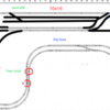
Given those items, My mind goes to this suggestion. Put a grade on each outer loop to gain some elevation for the back half of the layout. On the right side, continue the curve, to bring the mainline closer to the front of the table by a foot or so, then put a yard behind it. Perhaps model a Steel mill along the wall. The back part of the main can continue more or less to the left wall before dropping back down. Sort of a dogbone, with the left loop bent down.  I would put a mountain on the right side, and would find a way to put a small reversing loop or staging track for the URR in mountain. I would then have it switch onto the inner main in front of the yard, then switch back off as the left side was reached, to a spur for a slag dump

Yeah.. I know I hear people saying that mills were usually at water level, but Irvin works, on the URR, was on a bluff overlooking the Mon.


Attached is a very bad hacking up of your plan with some of some of my ideas.

Attachments

Images (1)
  • change suggestion

Justin, I'm glad you are starting to plan a more permanent layout.  You have a nice sized space for it.  I agree with the suggestions everyone gave above.  As Greg said it is nice to see someone else interested in the URR and P&LE.  Being from Butler County and living there again after a hiatus in West Virginia Western Maryland country, I model WM with an interest in the B&O.  Here in Butler we have the rolling mill turned carbon steel (Armco/AK) so I don't know blast furnace steel mills.  I like Greg's plan, and definitely agree with Chuck in recommending you check out George (G3750) PRR Panhandle 2.0 layout build topic based on Weirton Steel.  George has the room to go all out, but I'm sure there is a lot you can pick up and use.  He lives fairly close to me, so I have been to his place once, and he is a great guy!  I'll look forward to seeing your progress.

I have some general thoughts.    First, in any given space, an around the walls layout will provide more square footage for trains than a table top layout you walk around.     And with the layout against the walls, they can be used to expand scenery with backdrops for the good old PA hills, or for building facades - generally the rears since this usually faced the tracks.    So very large buildings can be represented with very little depth onto the layout.

You might want to also consider what  you want to do with the layout when you get it built.     It is really disappointing to put the last building in place and then think "is this all there is?".     Think about whether you want to just sit back and drink a cold one and watch stuff run round and round, or do you want to do something else like perhaps some operating including freight switching with car cards and waybills or a switchilst.     Neither idea is wrong, but how you want to use the layout when it is assembled does very strongly affect the track plan.   

Steel is big industry.   representing it mostly on the back drop is a big help in O. 

The mention of flextrack is very important.    Seriously consider it.    You want to learn new skills and working with flex track will require some.    However, the advantages of using it will be worth it.   You can be much more flexible in track planning and curve radius.    And brands such as Gargraves look so much better.     Also the less sharp switchers look better and cause less derailments.    And you can more easily put sidings closer together.

I'm not from Butler county, I am from Beaver County to the south.     However, I did work for Armco for the first 3rd of my career and went to Butler works often.    They did make steel, but as mentioned not in a blast furnace.    They had a large "new" electric melt shop.    A lot of their "charge" (or all of it) was scrap but clean scrap so as not to contaminate the steel grades.    They made STainless steel and electrical steel.    Electrical steel is made metallurically and then treated to be much more efficient for such things as motor cores and transformer cores.    It passes the current more readily because the molecules align, and it does not create nearly as much heat which is lost energy,     So modeling that operation, the melt shop would be pretty much enclosed and there are no blast furnaces.

A final thought, I model the area south Pittsburgh also - and rather loosely.     The line down the Monongehela Valley from Pittsburgh south was built as the Pittsburgh, Virginia, and Charlestown RR.    It was taken over and completed by the PRR in 1873 and rolled into the PRR in 1905 (30 years of operations under that name).    So if you are looking for another name, PV&C is a candidate.

I would definitely say take a second look at your track choice. I originally planned to use Atlas and didn't put too much thought into it but ended up switching to Ross switches once I started doing the track design for my steel mill. Ross has really awesome switches/slip switches/curved switches/etc. You can fit a lot more track work into a much smaller space. I bought some Atlas track before this happened so I'm still teetering between Atlas and Gargraves for the tracks. We'll see. Regardless, I would recommend you go back to the design table and see how much more you can accomplish with Ross.

Other than that, this looks to be a cool layout. Can't wait to see it come to life!

@prrjim posted:

I have some general thoughts.    First, in any given space, an around the walls layout will provide more square footage for trains than a table top layout you walk around.     And with the layout against the walls, they can be used to expand scenery with backdrops for the good old PA hills, or for building facades - generally the rears since this usually faced the tracks.    So very large buildings can be represented with very little depth onto the layout.

You might want to also consider what  you want to do with the layout when you get it built.     It is really disappointing to put the last building in place and then think "is this all there is?".     Think about whether you want to just sit back and drink a cold one and watch stuff run round and round, or do you want to do something else like perhaps some operating including freight switching with car cards and waybills or a switchilst.     Neither idea is wrong, but how you want to use the layout when it is assembled does very strongly affect the track plan.  

Steel is big industry.   representing it mostly on the back drop is a big help in O.

The mention of flextrack is very important.    Seriously consider it.    You want to learn new skills and working with flex track will require some.    However, the advantages of using it will be worth it.   You can be much more flexible in track planning and curve radius.    And brands such as Gargraves look so much better.     Also the less sharp switchers look better and cause less derailments.    And you can more easily put sidings closer together.

I'm not from Butler county, I am from Beaver County to the south.     However, I did work for Armco for the first 3rd of my career and went to Butler works often.    They did make steel, but as mentioned not in a blast furnace.    They had a large "new" electric melt shop.    A lot of their "charge" (or all of it) was scrap but clean scrap so as not to contaminate the steel grades.    They made STainless steel and electrical steel.    Electrical steel is made metallurically and then treated to be much more efficient for such things as motor cores and transformer cores.    It passes the current more readily because the molecules align, and it does not create nearly as much heat which is lost energy,     So modeling that operation, the melt shop would be pretty much enclosed and there are no blast furnaces.

A final thought, I model the area south Pittsburgh also - and rather loosely.     The line down the Monongehela Valley from Pittsburgh south was built as the Pittsburgh, Virginia, and Charlestown RR.    It was taken over and completed by the PRR in 1873 and rolled into the PRR in 1905 (30 years of operations under that name).    So if you are looking for another name, PV&C is a candidate.

prrjim hit all the points I would make, most especially regarding what you want to do with the layout once built.

Think about whether you want to just sit back and drink a cold one and watch stuff run round and round, or do you want to do something else like perhaps some operating including freight switching with car cards and waybills or a switchilst.     Neither idea is wrong, but how you want to use the layout when it is assembled does very strongly affect the track plan.

The Plywood Empire Route (a much smaller and less ambitious project than yours) evolved over time into a mostly switching pike because through experience I found this kind of Operating to be most interesting and satisfying for me. It is an around-the-walls layout and watching the train roll is part of the enjoyment but by now if I removed one track switch and turned it into a point-to-point Pike the PER would still retain most of it's character, charm and usefulness for me.

Phew! After a much too long hiatus, I'm finally getting back to the layout planning/building.  Thank you all for the great input.  I know this is going to be pretty ambitious, but I'm definitely up for the challenge.  To start, I've made some decisions in the planning and what I want out of the layout. 

  • Track: Gargraves.  I feel like this is going to be the better way to go.  I can use flex track, I can cut pieces to size to fit. 
  • Switches: Ross, although I don't have any of these on in the deign yet.  I'm open to suggestions on how to integrate a few between the lines.
  • Command System: DCS for now.  I still need to get a system, but I already have a Z-4000 and many Z-1000s.
  • What I want out of the layout: I want to have something with texture and layers.  I'm focused on having a nice urban area thats disconnected from a small town.  Its what I grew up with in the Mon Valley.  This means, I'm probably going to be a looper for the time being.  I also want to have a commuter rail line.  I have the MTH P&LE commuter set that I've ran nearly every year on my Christmas Layout.  I want to be able to connect the small town to the urban area with that.  In the scenery department I really want at least one area that looks like the Mon river along 837.  So I'm channeling some insights from Patrick H's layout.
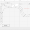
  • Layout Design: Due to my space constraints, I'm not going to have room for heavy industry.  For that, I'm going to employ some backdrops, and flats.  There may be room in the future for some industry but thats TBD.  I also pulled a lot of inspiration for this from @David K. Simpson's design in his thread.  As soon as I saw the upper and lower level cross over, It made me realize this is what I want to do.  The "high-line" will be 6 inches above the table platform and use an MTH dual track bridge to cross over the "level route."  I'll start the incline about halfway through the curve on the urban side, and have it end the same spot near the town.  Also, I squeezed in 2 more feet of real-estate. Shh.  haha
  • Future Plans: Last night as I was looking over the plan, I realized I may want to work in a small yard/engine service area.  I could probably get 2 more feet of space off the side with the town.  I was thinking just a small 2-3 track area where I could tie off the commuter train and maybe have a few industrial trains that can run on weekends or between revenue runs of the commuter line.  Again, any thoughts on it would be super helpful!


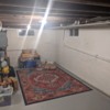
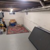
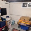
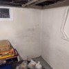
I've attached the new layout plan and some pictures of the space I'm working with.  The one ground rule my wife gave me was she doesn't want it jutting out into the sightline when you look down the stairs, thats why I have the town section more blunted.

Let me know any of your thoughts!  I'm an open book!

Thanks!

Attachments

Images (5)
  • Screen Shot 2021-03-17 at 8.29.09 PM
  • PXL_20210314_031018724
  • PXL_20210314_031036187
  • PXL_20210314_031101533
  • PXL_20210314_031104058
@Greg Nagy posted:

A few resources I forgot to mention yesterday:

PghTrainFanatic's Youtube channel - Western PA theme with a steel mill and a relatively small footprint.

DJ's Trains Youtube channel - CSX engineer that models and provides many resources for modelling the Mon Valley. Works in N scale but lots of useful stuff

Both of the links point to PGHTrainFanatic.  Is this what you intended to include for DJ's trains:  https://www.youtube.com/user/djstrains ?

Justin, Your room looks good.  On the last photograph it looks like paint is flaking off.  Is any of that area moist?  The narrower separation area between the city and suburban town is a good idea.  I think the track plan image is blurry, but my eyes make it blurrier still.  It looks like the rectangle at the right of center leads tracks over top of others.  To the left of that, there are some crossovers, but I can't tell if that is crossings at grade or a bridge.  Growing up and living in Butler County and going to college in Pittsburgh, I will look forward to seeing what you come up with.

I daydreamed a lot of years away without building much past benchwork before we would move somewhere.  Go for it and enjoy it and tear it up and do it again in 3 or 5 years!  My thought is 'Don't let DCS bog you down' - you have 3 independent loops so you can control each just fine with very little technology.  That said, you'll learn so much by doing!  Have a 'bias for action' vs a bias for planning, is what I have learned.  I end up modifying my plans almost immediately when I get into the physical world anyway!

You’re planning on the same bridge as I have in about the same position so I will tell you ahead of time it looks easier on paper than reality. The issue is the supports on either end. To do what you want (which is the same as what I wanted and did) you will end up with all kinds of clearance problems for the trains passing underneath. I had to get creative and adjust the angle of the bridge quite a bit. You have the top level drawn much better than I did but I think you’ll have to shallow out the S curve below. I spent many hours with the upper deck loosely in place while running cars and locos both ways on both lower tracks watching for both mid car and end of loco clearances. I had it where I thought it was perfect and then found out I couldn’t get certain locos to go over the bridge without hitting the sides! I guess my point is, I quickly found out the software will allow you to do many things that just won’t work in the real world. If there’s anything at all I can do to help or pics I can provide please don’t hesitate to reach out as I’d be happy to share my experiences and results. I’m far from the experienced experts here, but quickly realized how steep the bridge clearance learning curve is.

Add Reply

Post
The Track Planning and Layout Design Forum is sponsored by

AN OGR FORUM CHARTER SPONSOR

OGR Publishing, Inc., 1310 Eastside Centre Ct, Suite 6, Mountain Home, AR 72653
800-980-OGRR (6477)
www.ogaugerr.com

×
×
×
×
Link copied to your clipboard.
×
×