Situation:  There are two separate lines controlled by the separate throttles of a ZW.  On one line is a locomotive that when the power is abruptly shut off, will still coast.  The other throttle controls a line having a diesel engine that does not coast if the power is shut off, but just stops.  The consist of that diesel is quite long and has some die cast K-line coal hopper cars (6) in it.

Problem:  If there is a short on the locomotive line, the circuit breaker causes the entire ZW transformer to cut off power to the other line as well.  The inertia of the heavy consist causes the diesel to derail in the front, presumably due to the pressure of the consist and the diesel not being able to coast when the power is turned off.  Essentially a derailment on the locomotive side will likewise case a derailment on the diesel side for me in that situation. I assume this is so because the transformer has common grounds and does not have truly independent channels of operation.

Question: Is the new ZW L wired differently to have truly independent controls?  As a solution, instead of my separating the lines with entirely separate transformer so that a short on one side will not cause my problem, is there someway to wire the ZW to allow independent functioning of the throttles in terms of circuit breakers?


Last edited by GG-1fan
Original Post

Replies sorted oldest to newest

You can add circuit breakers between each throttle and the track they power. Doing so will solve the problem you are currently having, and as a bonus, will trip quicker than the one in the ZW which can prevent damage to newer electronics in modern engines.


The ones I used with my ZW were sold by Scotts odds and ends, but I think he closed his doors a few years ago. I am sure someone will chime in with a more available alternative.


Hope this helps,


J White


Originally Posted by j white:

Doing so will solve the problem you are currently having, and as a bonus, will trip quicker than the one in the ZW which can prevent damage to newer electronics in modern engines...

There is no breaker fast enough to prevent damage to newer electronics in modern engines. Breakers protect the wiring and transformer from over current. For the electronics, you will need transient voltage suppression to clamp damaging over-voltage spikes.

The O-gaugers who bought Scott's have an Ad banner at the top of the page. Train Electrics or such, I don't remember.  Their #231-631-0447


Good advice from Rob regarding installation of inexpensive TVS to protect the fragile wires and solder traces on your Locomotive circuit boards. As he noted breakers protect the transformer against overcurrent.  On the other hand TVS protect against voltage spikes. TVS are less than 50 cents each.

An electronics damaging voltage spike will not trip your breaker, only a current surge will.

Last edited by Dewey Trogdon

I agree with Rob about using circuit breakers on the output terminals of any ZW.

Not sure about the new ZW's but the post war ZW only has the circuit breaker covering the common side of the transformer, so if it trips the whole transformer shuts down.


7 or 8 amp at 120 volts should do the trick. Mouser Electronics sells the circuit breakers and TVS units, the purchase of four 7 amp circuit breakers(691-CMBO7311C3NBA) and 32 volt AC bi-directional TVS units at Mouser will be almost half of what Scott's charges. The only thing is that Scott's puts it into a small plastic box for you.


Lee Fritz

Last edited by phillyreading

As some other members suggested, I went with the Mouser Electronics solution,  I used their 10 AMP re-settable breakers, and the TVS (transient voltage suppressors).... I am using 4 Post War  ZW's to power my layout and this solution works great.,..  I am using both TMCC and LEGACY and I haven't had one issue....   I have had 2 derailments and the breakers "tripped" quickly and they're easy to reset.  


I chose to mount my breakers directly under the ZW's which I built a shelf for that sits just beneath the layout table top....  I shot some photos of how I did mine, each breaker is mounted in a drilled hole directly beneath the throttle handle that it is protecting.  The breaker is mounted in line so the hot off the transformer goes straight to one side of hte breaker then the other side goes to a terminal "barrier" strip... from their I can run that throttle's power wherever I need it to go.  Hope this idea helps, good luck.   

DSCN2206

DSCN2205

Attachments

Images (4)
  • DSCN2206
  • DSCN2205
  • DSCN2207
  • DSCN2204

TVS protecting one throttle's power district of a pw ZW[fuzzy photo]. Connected "across the line" Hot to Common binding posts.

Second photo: TVS on T-strip that is distributing power to one power district from 180 watt Power House. Terminal strip enables wire runs for multiple track feeders to the power district. Plate jumpers energize all screw positions on both the Hot and Common sides of the T-strip------white indicates Common, green Hot.  

IMG_1762-001

IMG_2070

Attachments

Images (2)
  • IMG_1762-001
  • IMG_2070
Last edited by Dewey Trogdon
Originally Posted by chris a:

I chose to mount my breakers directly under the ZW's which I built a shelf for that sits just beneath the layout table top....  I shot some photos of how I did mine, each breaker is mounted in a drilled hole directly beneath the throttle handle that it is protecting.  The breaker is mounted in line so the hot off the transformer goes straight to one side of hte breaker then the other side goes to a terminal "barrier" strip... from their I can run that throttle's power wherever I need it to go.  Hope this idea helps, good luck.   

DSCN2206

DSCN2205

Chris:  I see the connection from the breaker to the transformer, but the other wire that goes to the terminal strip is ultimately connected to, I assume, the common post of that transformer.  Does your mounting of the circuit breakers cause you any inconvenience in resetting them if they are tripped?  Thanks

GG1fan:  


Sorry the photos dont' show the perspective to the layout very well..   Addressing your questions: 


The red lead goes from the A post to one side of the breaker, the other side of the breaker goes to the hot Center rail of whatever block I am powering... in my case I send it through a terminal strip... But the breaker is on the Hot AC side, terminals A,B,C or D of the transformer...   Its tough to see the TVS but I hooked them up directly across the "A: and Common post on the ZW just like the photo in the post above shows....  


The black breakers in the photo are on the operating side of the ZW's where I stand to run trains, so if a breaker trips, the button pops out and instead of seeing black you see white, simply push it in and its' reset...  Couldn't be easier or more convenient plus by mounting them directly below the throttle handle they are protecting I know exactly where the short occurred or vice versa,once I see the derailment, I pretty much know which throttle is controlling that block.   I could send you another photo if you're interested...   

For those wishing to install re-settable circuit breakers on the four outputs of your pw ZW, one mounting solution is to install the four breakers in a plastic "breaker box" made from a project box from Radio Shack, ALLelectric catalog or other supplier.


A mounting alternative is to use 1/8" Masonite as a "mounting front" for a Breaker Board or Panel. [small 2x2 Masonite panels available from Lowe's and Depot.


Both the plastic box and Masonite are easily drilled to receive the round breakers. I have used the 1/8" Masonite for mounting volt and amp meters and toggle switches.


Photo below of old 1/8" Masonite 10 meter panel and my toggle control panel track schematic of Tortoise track switch motors. Minature toggle switches mounted in a "front" of homemade wiring box[controls on a small attic layout].

Previously I have used aluminum panels for mounting switches, meters, etc, but find Masonite easier to work with.

IMG_1991-001

IMG_1782

Attachments

Images (2)
  • IMG_1991-001
  • IMG_1782
Last edited by Dewey Trogdon

The postings on here have provided me with some inspiration for interesting projects over the next several months to upgrade the electrical aspects of my layout.  I plan to make some traditional types of power blocks on my layout as well as meter installations in conjunction with circuit breaker systems.  I am curious about the purchase of appropriate panel meters, specifically amps, voltage, and wattage meters, for a AC layout as shown in Dewey's photos.  I can assure you that once I begin these projects, you will be haunted by my continual questions and problem areas as I go forward.  Bear with me in this evolutionary process.  I would certainly appreciate the help.

GG-1 Fan


Analog AC Panel Meters:

Google Light Object for info and orders. They have inexpensive AC panel meters that are adequate for monitoring Toy Train power districts. You need an Amp meter and Volt Meter for each power district.


Panel Amp Meters 0-15 amp scale:  SKU-AAC15A $9.50 each. [wired inline-in series]


Panel Volt Meters 0-30 volt scale:   SKU-EMPAAC30V $9.50 each.[wired across the line-in parallel]


There are other brands, some more expensive but essentially the same Foreign made meter with +/- 2% variation.

I have used DER 670 AC analog panel meters for years and once imported and sold them on the Forum. Assembled in Taiwan from Japanese components and distributed from New Zealand. The Light Object meters are imported from the Pacific Rim and will do the job just as well. 


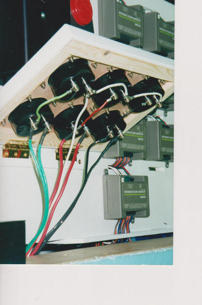
Photo below showing wiring for an old three power district meter panel. Volt meters top row, amp meters bottom row. White wire is Common-- Black,Red and Green are Hot conductors from 3 districts.


Linn W

Attachments

Images (1)
  • Linn W
Last edited by Dewey Trogdon

Thanks Dewey, I appreciate the photo showing the wiring for the meters.  It is helpful.  Now each of the hot pairs going into the amp meters--since the white wire is common, is one of the hots of the pair connected to a transformer post and the other to the track?  If so, which one is connected to which side of the meter, or doesn't it matter? (I hope I'm making myself clear here).  If I am using a ZW, do I only need one common (white) from any one of the four common U posts?  What I am trying to decipher is from where are the wires coming.  Also if I incorporate circuit breakers, where do they fit into the meter wiring--the hot coming in or the hot coming out?

GG1fan

If powered by a pw ZW the 3 Hot wires would be running from the A,D and either a B or C post to the meters and from the meters to the center rail of the three individual power districts[black, red and green]. The white Common wire would originate at any "U" post on the pw ZW and connect only to the three Volt meters and from there to an outside rail of each power district.


The individual Hot wires from the pw ZW connect to the inbound post of the three Amp Meters and exit on the outbound post to the track center rails[the Hot jumper from the Amp Meter inbound post up to the volt meters is simply a "Daisy Chain"to establish a circuit on the Volt Meter via the Common. Has nothing to do with the amp meter readings.].


The entire load of each power district goes through its respective Amp meter via its respective Hot wire.Therefore you will note that the wire run is from the transformer to meter,through the meter and from meter to center rail[via T-strip]. 


The particular meter panel exhibited is wired to  three different 180 watt PoHo Transformers powering three different power districts--coded black, red and green. The Commons from all three are connected to a Layout Distribution Terminal Strip [photo] and from there a single white wire to the Voltmeters represents the Common on all three--a "Layout Common". However, the three Hot wires are under no circumstance connected to one another.


I assume you are asking about external breakers. Circuit Breakers are connected inline on the Hot conductors--a breaker for the Black code district , one for the red district and on for the green district. So, your external Breaker is located between the Hot post on the transformer[s] and the train load on the rails via connection to Center Rail. Internal breakers inside the transformer function much the same. 


Keep in mind a basic factor--all circuits are made between a Hot and a Common. The Hot feeds the center rail and the Common an outside rail. The engine pickup roller rides the Hot center rail and feeds the motor which is also connected to Common return of the frame, axles and wheels on the outside rail thereby creating a circuit between Hot and Common and---a powered train. 

Hope this helps--if not keep asking, a lot of Forum folks can help. 

Attachments

Images (1)
  • IMG_1783
Last edited by Dewey Trogdon
Originally Posted by MichRR714:

Here is my current setup.  I really thought about using breakers.  I just don't trust them enough so decided to stick with fast blow fuses.  So far I've had good luck protecting my trains that way.


I appreciate your input about fast blow fuses.  Where do you incorporate them in the wiring scheme with your meters--before entering the meter or coming out?

Add Reply

Post

OGR Publishing, Inc., 1310 Eastside Centre Ct, Suite 6, Mountain Home, AR 72653
800-980-OGRR (6477)
www.ogaugerr.com

×
×
×
×
Link copied to your clipboard.
×
×