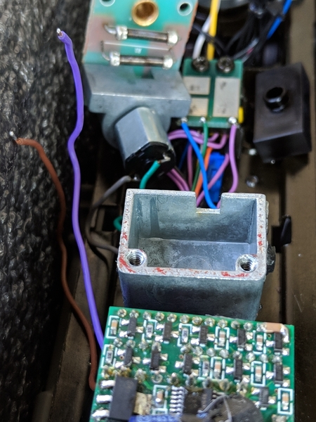
Hi guys, so I recently aquired a PS2 SD70M with a bad smoke unit. I wanted to see why the smoke unit failed so I took the shell off to see if the resistors were bad and just needed to be replaced. I can hear the fan spinning but no smoke.

Well I wasn't happy to find a burnt component on the main board. See picture below:

Screenshot_20180729-140957

So my question is, can I replace this? I have fairly good soldering skills and this part it's too small so I think I can tackle this project.

This is a PROTO2 MTH Premier SD70M PART # 20-2288-1

My next question is, why did this happen? The resistors on the smoke unit are pretty bad, like they were left on and dry for a while, not to mention the batting was KFC Extra crispy. This smoke unit has two resistors and when I place my meter on them, they give me a value of 9ohms, this seams like a lot. no?

I don't want to place the engine on the track until I get all this squared away.

Thanks for the help as usual!

Attachments

Images (1)
  • Screenshot_20180729-140957
Original Post

Replies sorted oldest to newest

1. Yes, you can replace that $1 transistor:

https://www.digikey.com/produc...NDT3055LCT-ND/244307

2. The 9 Ohm measurement is two 16-Ohm heater resistors in parallel (nominally 8 Ohms = 16 /2) so 9 Ohms is well within tolerance.  That the wick is burnt to a crisp could simply mean someone ran it without fluid for an extended period.  But even with a crispy wick, the transistor should be able to drive 9 Ohms OK. 

As to why the transistor failed is a good question.  A wiring-short between one of the smoke heater resistor wires and the chassis metal frame could cause a failure so check the integrity of the wiring and insulation from the circuit board to the smoke unit. 

If you are comfortable/handy with a DMM making voltage measurements, I'd ask you to remove the transistor (which looks like toast anyway) and measure the control voltage going to the transistor to make sure it isn't "stuck" in the ON state.  If it's stuck on, you could have additional issues.  That is, the circled part seems unusually dis-colored but that could just be a photo reflection or artifact.  Point being, there could be additional damaged components.

In any case, the control voltage to the transistor (measured between the pads as shown) should be 0V DC when smoke is OFF, and then rise proportionally to the smoke volume which you can adjust if you have DCS command capability.  Or, if you operate conventional, you can adjust the track voltage and watch the transistor control voltage change inversely to the track voltage.  The DC voltages will be in the 1V or so range.  More specifics if you're interested.  Otherwise, just change the transistor and see what happens.

Screenshot_20180729-140957

Attachments

Images (1)
  • Screenshot_20180729-140957
stan2004 posted:

1. Yes, you can replace that $1 transistor:

https://www.digikey.com/produc...NDT3055LCT-ND/244307

2. The 9 Ohm measurement is two 16-Ohm heater resistors in parallel (nominally 8 Ohms = 16 /2) so 9 Ohms is well within tolerance.  That the wick is burnt to a crisp could simply mean someone ran it without fluid for an extended period.  But even with a crispy wick, the transistor should be able to drive 9 Ohms OK. 

As to why the transistor failed is a good question.  A wiring-short between one of the smoke heater resistor wires and the chassis metal frame could cause a failure so check the integrity of the wiring and insulation from the circuit board to the smoke unit. 

If you are comfortable/handy with a DMM making voltage measurements, I'd ask you to remove the transistor (which looks like toast anyway) and measure the control voltage going to the transistor to make sure it isn't "stuck" in the ON state.  If it's stuck on, you could have additional issues.  That is, the circled part seems unusually dis-colored but that could just be a photo reflection or artifact.  Point being, there could be additional damaged components.

In any case, the control voltage to the transistor (measured between the pads as shown) should be 0V DC when smoke is OFF, and then rise proportionally to the smoke volume which you can adjust if you have DCS command capability.  Or, if you operate conventional, you can adjust the track voltage and watch the transistor control voltage change inversely to the track voltage.  The DC voltages will be in the 1V or so range.  More specifics if you're interested.  Otherwise, just change the transistor and see what happens.

Screenshot_20180729-140957

The part has been ordered. I unslodered the bad transistor and checked all of the wiring and didn't get anything strange but just in case, I disconnected the heat elements by unslodered them from the smoke board, just to not even have a load on that system until  I get the part. I then put it on my test track and just applied power (didn't "start up" the engine) it moves forward and back a few feet just fine as is. I tested the points with my meter and get zero, engine sitting in the state mentioned before. I hope that means all is still fine with the board.

I'm going to rebuild the smoke unit as well, as to have that ready. Is there any way I can bench test the smoke unit before connecting it to the engine again. I don't want to have to work twice.

I'm also going to do a twice over of the wiring which isn't very long but I just want to make very very certain I didn't miss anything.

Thanks for your help Stan and GRJ!

ALWAYS VERY MUCH APPRECIATED!

Screenshot_20180729-140957

I don't know the exact smoke unit you have so I refer you to the 4-pin connector on your circuit board which I know exactly what you have! 

To bench-test the smoke unit (disconnected from the PS2 electronics board):

Since the smoke heater resistors are 9 Ohms, you can calculate the Watts of heat using the simple formula Watts = Volts x Volts / Ohms.  So if you apply, say, 5V (AC OR DC) to the resistor pair, you generate 5V x 5V / 9 Ohms = ~3 Watts.  This will be a moderate amount of smoke.  7V or ~5.5 Watt is a healthy amount of smoke.  9V or 9 Watts and you'll need to open a window!

You want the fan running to blow the smoke out.  The fan voltage must be DC.  If you have a DC bench power supply then great.  If not, connect 2 or 3 AA 1.5V batteries (3V or 4.5V DC) with the indicated polarity (FAN+ and FAN-).  Be sure you get air-flow - since you say the smoke unit is broken it could also be that the so-called "impeller" or fan-blade has come loose from the motor shaft.  You'd hear the motor spinning (as you apparently do) but no air flow.  Since you're pulling the top of the smoke unit off anyway to refurbish the wick, inspect the impeller-shaft connection.

Attachments

Images (1)
  • Screenshot_20180729-140957
Last edited by stan2004

OK guys, here is the update.

I received the new transistor (or transistors because they were dirt cheap) and replaced it on the board. Everything went without a hitch. Here is a picture of the final result: (Before you say anything about the hot glue LMAO, the cap was cold soldered to the board and from lifting and lowing it, it finally came loose, it was a PITA to re-solder so after I got it  soldered I decided to make it a permanent fixture for the moment.)

IMG_20180802_193244

So after this I went straight to the test track, I began by just applying track voltage but that is all. Measurements across the Gate and Source "Control Voltage" was zero and no voltage across the blue and brown "HEAT" wires (They are currently disconnected from the smoke unit until I figure this out), so far so good.

Next I "Started up" the engine with smoke "OFF" and got the same results as before (on a side note, those little grain of wheat bulbs get HOTTTTTT!! LOL) so again, so far so good.

Now I turned on the smoke from the DCS Remote and the fan begins to turn. I get about .58V DC across G/S terminals on FET, 5V DC on FAN (DUHH its spinning, but I am being thorough. Also, for the record, STAN's pin-out diagram has been on the money) and about 4V DC across the HEAT circuit. The HEAT voltage seams to drop down to about 2V DC for a few seconds then right back up, but I figure maybe this is normal behavior to not over heat the smoke resistors (Please correct me if I am wrong.) When I increase the RPM level the voltage spikes, I saw 18V DC at moments but again, I figure this is normal as it only for brief moments and it must be to quickly heat the resistors.

Unfortunately this is where I now stand, when I momentarily touch the Blue and Brown wires to the opposite sides of the resistors with the smoke unit off and engine on, I get smoke and I shouldn't be. As of now this is what I have discovered; when I connect the blue leg only to the resistor and leave the brown disconnected, I get smoke (again with the smoke turned off, FAN is dead, and 0V DC on G/S terminals.)

I was obviously frustrated and went to bed to start fresh this morning before heading to work. The first thing that came to mind was to test continuity between the smoke resistors and the outer wall of the fluid chamber and as you might already be guessing, I have the smoking gun. The smoke elements or Smoke resistors are shorted to chassis ground via the outer metal casing of the smoke unit. How did this happen? What should I do now? Maybe just replace the gasket? with?

I am close to getting this guy 100% running and hope you gentlemen can help push me and this beautiful engine to the finish line.

P.s. if you guys are interested in seeing the voltage across the Blue and Brown wires with different RPM levels, here it is:

https://photos.app.goo.gl/tvdGjS6yuSLCaJMr8

Just maybe the video will help someone in the future.

Thanks!

Attachments

Images (1)
  • IMG_20180802_193244

Well the search is over, I opened the smoke unit up again to see how this was shorting out and for some reason I never noticed, nor had any reason to believe that the inner smoke unit wall had rub marks:

IMG_20180803_094104

It seems that the resistor closest to the FAN motor is slightly leaning towards the outer wall and is shorting out as a result. I am currently at work so I cant test this theory at the moment but I am fairly confident this is the issue. I cant believe it was staring me in the face this entire time.

I will update later this afternoon.

As always I appreciate everyone on this forum for coming together to help each other out as well as myself with this issue

Attachments

Images (1)
  • IMG_20180803_094104
Daniel J. Gonzalez posted:

...

Now I turned on the smoke from the DCS Remote and the fan begins to turn. I get about .58V DC across G/S terminals on FET, 5V DC on FAN (DUHH its spinning, but I am being thorough. Also, for the record, STAN's pin-out diagram has been on the money) and about 4V DC across the HEAT circuit. The HEAT voltage seams to drop down to about 2V DC for a few seconds then right back up, but I figure maybe this is normal behavior to not over heat the smoke resistors (Please correct me if I am wrong.) When I increase the RPM level the voltage spikes, I saw 18V DC at moments but again, I figure this is normal as it only for brief moments and it must be to quickly heat the resistors.

For an MTH PS2 diesel smoke unit, the measured DC voltage at the heater resistors should be relatively constant for a given RPM level.  You should not see 16, 17 or 18V DC across the heater resistors (even briefly) as that would suggest an enormous power flow into those resistors.  To wit, 18V DC across the 9 Ohm resistor-pair suggests 36 Watts of power which is out of the park.

This discussion gets somewhat nerdy but when measuring the voltage across Heat+ and Heat-, you need a resistor load between the two wires.  It doesn't have to be the low 9 Ohm load of the actual heaters - something like a 1K or 10K resistor would do.  It is true that your meter is a load but it's a tiny one - typically 10M for a digital meter.  I notice your finger on the test lead which represents a capacitance which can confound measurements when making unloaded or lightly loaded DC measurements on a FET in this type of circuit.  For example, if you squeeze the test probe against the wire a bit harder, the DC voltage might change!

And to continue the nerdiness, when you reach the point of measuring the voltage across the actual heater resistors driven by the FET, a DC meter will under-report the actual heating voltage.  This has to do with how the PS2 FET is pulsed on/off at a very high rate (in the kilohertz) to adjust the effective heater power.  Specifically, the power (Watts) in a resistor is proportional to the squared Voltage (hence the Volts x Volts discussed earlier).  Yet, a DC meter only measures the average Voltage.  Then the discussion degenerates into RMS meters vs. averaging meters and whether RMS applies to DC or just AC, blah, blah, blah.  Fear not, I am not going there!

Daniel J. Gonzalez posted:

Unfortunately this is where I now stand, when I momentarily touch the Blue and Brown wires to the opposite sides of the resistors with the smoke unit off and engine on, I get smoke and I shouldn't be. As of now this is what I have discovered; when I connect the blue leg only to the resistor and leave the brown disconnected, I get smoke (again with the smoke turned off, FAN is dead, and 0V DC on G/S terminals.)

Depending on how long you touched the wire(s) to the heater resistor (with it shorted to the chassis), there's a chance you blew the FET again.    Specifically, the heater resistor shorted to the chassis provides a circuit to AC track voltage (relative to the DC common in the PS2 circuit board).  FETs are essentially DC devices and don't like AC voltages.


stan2004 posted:
Depending on how long you touched the wire(s) to the heater resistor (with it shorted to the chassis), there's a chance you blew the FET again.    Specifically, the heater resistor shorted to the chassis provides a circuit to AC track voltage (relative to the DC common in the PS2 circuit board).  FETs are essentially DC devices and don't like AC voltages.

The FET isn't all that fond of the high currents a direct short to the track would yield either.

Well no glory today my friends. I'm guessing the short took out something else because I'm literally holding the smoke unit in my hand and it is still heating the resistors like it was when they were shorted. I'm going to give up before the board suffers any more damage. It is fully functional without the smoke unit so I am reluctant to give up but I know these 5v boards are very sensitive and I consider myself very lucky that I've gone this far and the board still works. This guy is going to get a PS3 upgrade some day soon, for now I'm just going to log miles with it as is.

Thanks for the help Stan and GRJ! I learned a ton about the 5v board with this project but I fear the real repair is beyond my reach.

I do plan on attending the MTH Tech School, my local HS wants to sponsor me, when my newborn gets a bit older, maybe when I do I can use this board as my first take at a true repair.

Have a great weekend my friends!

Add Reply

Post
The DCS Forum is sponsored by

OGR Publishing, Inc., 1310 Eastside Centre Ct, Suite 6, Mountain Home, AR 72653
800-980-OGRR (6477)
www.ogaugerr.com

×
×
×
×
Link copied to your clipboard.
×
×