
 I'm looking for info on what are the items on the front of boiler hatches on certain steam engines? They are in front of the Allegheny (2 of them). I see them on certain other steamers as well. I came across the description of this Pump, Westinghouse Cross Compound. I'm guessing that it's what's on the front?? They look real close to what I'm seeing.

http://www.accucraft.com/model...98-411-ALLEGHENY.htm
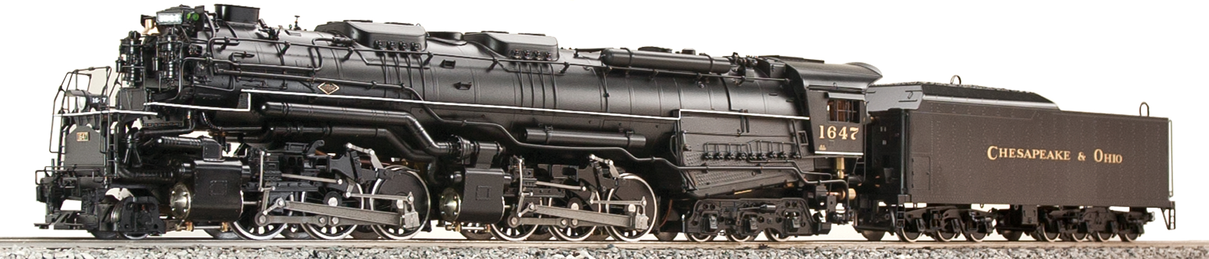
 

 What's it do/for????????  (air brakes?)

Original Post

Replies sorted oldest to newest

Those big cross-compound air pumps might be located almost anywhere on a steam locomotive.


Joe


Rich is certainly correct that air compressors were placed wherever they would fit on a steam locomotive.  Every 20th century American steam locomotive as at least one.


Some railroads like to mount them on the front of the boiler in the later steam days.  The C&O and the GN were just two railroads that were fond of that location.


Mounting one or two below the running board was also a common location.  That did have the disadvantage of putting the weight on one side of the locomotive and they were at least partially in the way of the running gear.  The compressors were usually on the fireman's side since the power reverse was on the engineer's side.


The pilot deck was also a popular location in late steam days.  The NYC was fond of mounting air compressors down on the pilot deck behind shields.


Watch out Joe.  Pretty soon you are going to be noticing which locomotives have dome or front end throttles, Worthington, Elesco or Coffin feedwater heaters or injectors. 

 You guys are being kind.

I have to do much more studying to pass!

It's embarrassing to ask these questions and I appreciate the info. I do have many train books now and try to read what I get my hands on. A guy sent me a book on B&O power that cover's 1829 to 1964. I'm afraid of where this could lead! I never heard of some like the KB-1? Lots of big steam.

 They show a picture and describe slide valves on a EL5 mallet?

 Hmmm, "there were more 2-6-6-2 Mallets built in America than any other type"!!

 I'm also scratch building and repairing equipment and don't know some of the thing's purpose that I'm fabricating.

Here's a drawing for you - a close-up if you will. 

http://trainperson99.home.comc.../air_pump_piping.jpg

Lower set of cylinders are high and low pressure air, with airflow right to left. Upper cylinders are the steam side high and low, steam flow also right to left. Piston rods visible between upper and lower cyls. Sometimes in movies or documentaries you will hear the slow chug of an air pump on a stationary locomotive in a station scene.

Hope this helps

Firewood


Nice drawing!  Thanks for the link.


Joe


Watch out, pretty soon you will start recognizing Proto 2 and Proto 3 accent sounds and where they were recorded.


https://www.youtube.com/watch?v=X-9dPuFf8XU


When I first saw UP 3985 and watched her rods get lubed with an Alemite gun I was impressed that it sounded just like the MTH model. 


Last edited by Ted Hikel
Jeez it's great to see other designers have those problems.  We are in the midst of designing a truck and we are shoe horning gear in just about everywhere.
 
Originally Posted by OGR Webmaster:

Those big cross-compound air pumps might be located almost anywhere on a steam locomotive. Wherever the designer could fit 'em in, that's where they went. There was no "standard" placement for them.


It is interesting to note the piping associate with these pumps.

(1.) There is air intake, which would be clean, limited smoke,  being the front of the locomotive.

(2.) Air to the air tank system. Locomotive tanks are usually front and along the sides.

(3.) Steam in, to drive the pump, controlled from the cab.

(4.) Steam exhaust, which is usually piped to the smoke box.

Other than inhibiting front smoke box maintenance, probably a good location for the air pumps.

Originally Posted by Firewood:

Here's a drawing for you - a close-up if you will. 

http://trainperson99.home.comc.../air_pump_piping.jpg

Lower set of cylinders are high and low pressure air, with airflow right to left. Upper cylinders are the steam side high and low, steam flow also right to left. Piston rods visible between upper and lower cyls. Sometimes in movies or documentaries you will hear the slow chug of an air pump on a stationary locomotive in a station scene.

Hope this helps

Yes!!

Add Reply

Post

OGR Publishing, Inc., 1310 Eastside Centre Ct, Suite 6, Mountain Home, AR 72653
800-980-OGRR (6477)
www.ogaugerr.com

×
×
×
×
Link copied to your clipboard.
×
×