What do you mean by traction supply ? you mean track power ?
I don't see how the AC track power from many different control rail can be run to only one bridge rectifier then to the relay - or relays ? If all relays are tied to one bridge rectifier then all relays would work at the same time. I'm missing something in your description of how you set up many different control rails so each control rail activates one relay .
Q. What do you mean by traction supply ? you mean track power?
A. Traction power is the railroad industry term for the power that operates the traction motors. I prefer to use that term, rather than the ambiguous term "track power" which can mean anything from traction power to signal power, to signal ground, to anti-derail wire, etc.
Q. I don't see how the AC track power from many different control rail can be run to only one bridge rectifier then to the relay - or relays ?
A. I did not say that. I do not mean that. You are putting too many words into a simple concept.
First, "AC track power from many different control rail(s) " is *NOT* "being run to only one bridge rectifier." The track COMMON, via the wheels of the train, is being run to one of the relay coil terminals. Relay D-C power is waiting on the other relay coil terminal. It is also waiting on *ALL* the relay coils. That is why it is called a common supply, (saving the need for many individual bridge rectifiers.) Since the D-C supply and the traction power share a common return, the relay operates when the wheels bridge the rails.
Q. If all relays are tied to one bridge rectifier then all relays would work at the same time.
A. No, each relay has its own "operate" wire (from its own section of track) to one side of each coil, and all the relays are supplied with D-C power on their other coil wires.
Q. I'm missing something in your description of how you set up many different control rails so each control rail activates one relay.
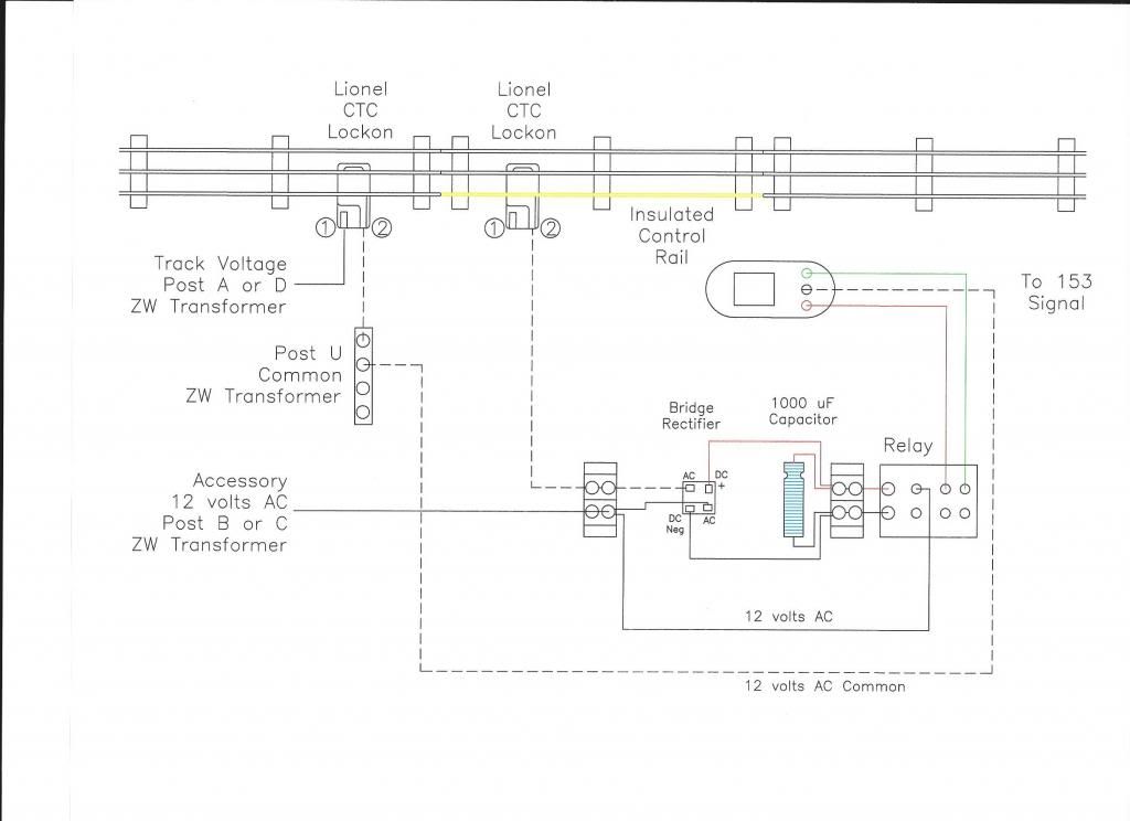
A. Here's the diagram: (draw it out on a piece of paper to understand it better)
COMMON lead from transformer > "regular" outside rail > wheels > insulated rail > control wire back > relay coil > HOT side of D-C supply (or A-C supply, if you prefer) > output of supply > back to COMMON. It's the same simple circuit that you seem to understand.
I think you are getting confused by the addition of the idea of using D-C instead of A-C.
Each insulated rail has its own control wire, which goes to its own relay coil. There is no interference, any more than there is when you turn on the light in your bathroom, and the light in the living room. They both have separate OPERATE leads (from separate switches) but they both have a COMMON wire (the neutral bus in your circuit breaker panel). For simple electrical components to interfere with each other, or to interact, they need to have TWO common wires. Think "horn" and "tail lights" in your car. Each has its own OPERATE wire, and they share a common chassis ground.