First, I don't have a lathe.  I want one but haven't decided on what to get.


I've searched the PSC and Stevenson catalogs (Today I got parts in the mail from Bob, so sounds like he's better) and neither have what I need.  


Anyone else know of aftermarket domes or sources?


I was thinking of taking some brass tube, cutting it, soldering in pieces to get what I need. Problem is the 'flange' for mounting to the boiler, not sure how to do that?


How do I shape the top of the dome-it's not flat and has rounded edges to the sides of the dome.  Use thin brass and bend/reinforce it on the underside?  Ideas?


This will be going on an FEF-1 for reference.


Thanks!

Last edited by 86TA355SR
Original Post

Replies sorted oldest to newest

I have a couple of lathes but you could use a 1/2 drill. I would use solid brass rod of a diameter at least as large as the base diameter. Using a drill motor you could shape the dome using files then use various grits of sandpaper until you get the desired finish. The base of the dome will be flat when you cut it off from the rest of the rod so you will have to shape the base with files or a Dremel to make it fit the boiler.


Pete

If you have a drill press that might be a better option as you won't have to deal with securing the drill motor. Before I got my machine tools I did a lot of work with just a drill motor. Just takes patience as you won't be able to remove material as fast as you can with a proper lathe and shaped cutting bits.


Pete

Originally Posted by Up with UP:

You might try an auto parts store and look at their brass freeze plug selections. The come in a lot of diameters and some have deep shoulders that could be dremeled to the correct boiler radius.  Just a thought.

That's an outstanding idea, I have some in my workbench from my drag racing days.  I'll see what I can come up with.

Umm - that was my very first dome.  It cannot be done on a lathe, because it is oblong - maybe oval in shape.  It was a very long time ago, but I think I simply hand- filed a block of brass.


The bottom, or skirt, is just a piece of .020 brass cut to shape and clenched by the dome. If you need a fillet, that can be done with solder or body putty.  You may find that no fillet is required to get a very realistic bottom.


Most Scale Craft models do not have this skirt - I add them.  I also add riveted skirts to Lobaugh tank car domes - really jazzes them up!

86TA are you doing the FEF1 with the original all round domes? Are you modifying an existing locomotive. Is it brass ?


If the dome is round, I would do as Norton suggested. If it is oblong do it like Bob 2 suggested. I would probably build an oblong from sheet brass soldered together and filed. Brass bar stock would be cool to work with though.


Ron 

Originally Posted by Ron H:

86TA are you doing the FEF1 with the original all round domes? Yes, circa 1937.  The sound dome is oblong and is my next major task.


Are you modifying an existing locomotive. Yes, a Weaver FEF-3 was sacrificed.  I realize it won't be a dead accurate model, but my goal is to do a good job on my first major brass project and make it as accurate as possible.


Is it brass ?  Yes


If the dome is round, I would do as Norton suggested. If it is oblong do it like Bob 2 suggested. I would probably build an oblong from sheet brass soldered together and filed. Brass bar stock would be cool to work with though.

 I need one of each, so I'll do some experimenting. 

Here's what I'm building-photo copy righted by UPHS. 


photo [27)


Here's a few quick pics:


photo [25)

IMG_6752

IMG_6783

IMG_6806


My stack needs some work-need to shorten it up slightly and some other things.  It's the correct diameter for a 'Little 800' but is to tall.


IMG_6805


I'm currently building the front out of brass and PSC parts.  Takes a lot of time...


IMG_6809


I got some good ideas from you all, so I'll finish the front of this thing and get cracking on the domes.

Attachments

Images (7)
  • photo (27)
  • photo (25)
  • IMG_6752
  • IMG_6783
  • IMG_6806
  • IMG_6805
  • IMG_6809
Last edited by 86TA355SR

I am officially impressed.  Yes, stacks are made on a lathe.  Good used lathes are available for under $500.  Get the biggest one your wife will allow in the garage, with three jaw and collets.


When buying brass bar, get leaded brass, or "free cutting" brass.  Don't be tempted to use an old piece of marine bronze or something.  And buy new files - good ones.


When you finish that, you will be ready to attempt scratch building.  It is very satisfying to know you can build any steam model you want.

The work looks great! It will be one tough looking locomotive.

The nice thing about doing your own work, if you don't like what you've done, you can tear it up and do it over. I have to do that all the time. It's also good to walk away from it for a day and come back with a fresh perspective.


Keep it up!


Ron

Originally Posted by Steam Guy:

Nice work!


Could you please explain how you filled in the large hole where the double smoke stacks were.  That is a large opening and you did a great job filling it in.  That also goes for the area where the sand/steam dome was.


Thanks in advance,

Steve

Since that model is brass, it looks like he simply used some sheet brass, bent it, cut it to fit properly, then soldered it in place. Afterwards, filed and sanded the solder joints.


Very nice job, too.

It is actually fairly difficult to get a patch like that perfect.  I use an underlay of brass, attached with flathead brass screws, then carefully shim and screw the patch to that.  Then liquid flux is applied, and solder is allowed to flow by using a pencil torch.


Then screwheads are filed flush, and any errors are filed or filled.


It does look like he merely fitted the patches, as Hot Water says.  He is an artist.

Last edited by bob2

Ron, thanks.  Your CF looks great.  Can't wait to see more.


Steam Guy, I did pretty much what How Water said.  I made a template from masking tape, rolled the brass sheet to match boiler curvature, transferred tape template to brass and carefully cut it.  Looking back, it may have been easier to make a whole new boiler.


Thanks for all the nice comments.  As bob2 said, I love the thought of having locomotives I've always wanted without being dependent on the manfs.  Plus, you can build anything you want.  

You asked how I bend brass wire. The front hand rail on the cab forward was bent from .050" brass wire or 1.3mm. I use a mandrel from anything round and metal and work it with my thumb.


Here is a video of me bending a curve in a thicker brass wire. Lots of groaning.

Sorry! Strong hands help.


Ron


Attachments

Videos (1)
mandrel
Last edited by Ron H

86TA355SR 


Thanks for responding to my question.


What I had meant to say is:  once you have the patch fabricated how do you hold it in position for soldering? Looking at your photos it appears that you made the sand/steam dome patch (which is shown before soldering) as such that it is wedged into the opening, hence it is being hold tightly in place, just enough for soldering.


Is this true?


I can understand how Bob2 handles such situations; many thanks Bob for all those articles on building in brass in 48/ft magazine and other magazines over the years.


Steve

I tried to find a source for brass domes, and called one guy, and he was just out of

the hospital and didn't sound like he could supply anything, so being one of those

"I want it NOW!" people, I found wooden furniture buttons in a craft store, mounted

them on to styrene tubing, sanded them to shape...they LOOK good, would have

rather had something more substantial, but man~ana doesn't get it, and I have

finished this Lionel kitbash, that is, for the loco...looks like I may have to scratch

build the tender, as nothing looks close.  There is never an O scale show going on when you need one.

Originally Posted by Steam Guy:

86TA355SR 


Thanks for responding to my question.


What I had meant to say is:  once you have the patch fabricated how do you hold it in position for soldering? Looking at your photos it appears that you made the sand/steam dome patch (which is shown before soldering) as such that it is wedged into the opening, hence it is being hold tightly in place, just enough for soldering.


Is this true?  Steve, that's correct.  The 'patch' was cut slightly over size and then gradually filed/sanded to a tight fit for the opening. I used 3M auto trim tape inside the boiler to 'hold' it during soldering.  The tape is very sticky and thick, great stuff with excellent holding power.  It was critical the patch didn't move as I soldered it.  Then, I soldered one corner.  Did the far opposite corner next, allowed to cool.  Using leather gloves I was able to 'nudge' the piece where needed to align with the boiler curvature as I soldered.  Had a little help from the wife, as I needed an extra hand a few times.  She griped about the smell of solder, but thought the end result was cool   I think I answered 33 questions from her during this process.  I nicknamed her "Mrs Mechanical' years ago.  


I'm sure there's an easier way, but it was all I could think of at the time.  This piece was much easier than the stack patch...It still needs some filing to be smooth. The round part was hard to cut and required a lot of filing to fit.


I can understand how Bob2 handles such situations; many thanks Bob for all those articles on building in brass in 48/ft magazine and other magazines over the years.


I need to find those articles.

Ron,

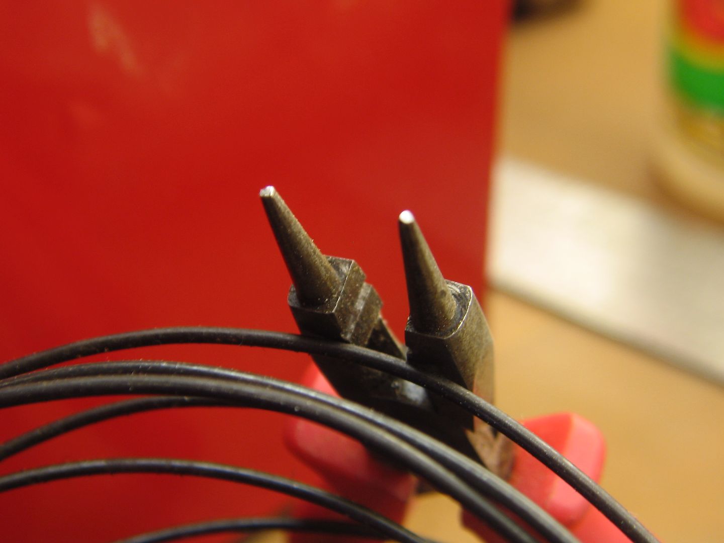
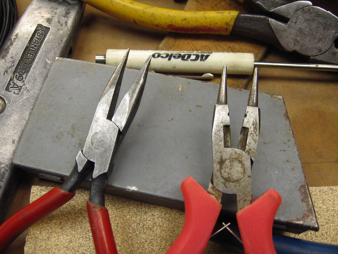
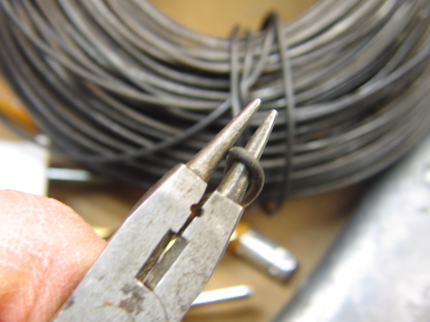
Thanks for the video and taking the time to share it.  Your method is how I've done it in the past.  I recently picked up some pliers similar to what Mike CT showed (where did his reply go?) and they work great.


I hope to make some progress on the domes Saturday.  


Thanks again for all the help. 

Formerly a Williams brass USRA Mike; now a GM&O Heavy Decapod.


The sand domes were cast using 2-part mold material from a hobby shop. I found a loco in my collection (a Lionel SOU 4501-prototype Mike, actually) with a virtually identical dome, per photos of the GM&O locos,  that was removable, mixed the material and formed it around the dome, dome-bottom-down.


Poured tin-antimony solder (from the hardware store) melted on the stove, let cool. Hard solder; durable. Had to dress the top of the dome (this was a simple, 1-part mold) to shape, then added brass or styrene (I forget) for the sand hatches. Detailing on the domes could have been further dressed/enhanced, I suppose. I was satisfied. Then epoxied domes in place on boiler.


Similar story on the steam dome.


This technique allows you to borrow shapes fairly easily.


I do table-grade modeling; if you are looking for Fine-Scale, this technique is probably too seat-of-the-pants. I'm happy with it.


DSCN1219

Attachments

Images (1)
  • DSCN1219

I like it!  Very nice model.  All Nation uses a lead alloy dome, and nobody complains much.  I sort of stick to brass, but am not averse to making a master and giving it to Stevenson.


Somebody asked about the tapered rods for the FEF - I am not sure, but I think my better set is in Bob Stevenson's collection.  One of Harmon's buddies may have my somewhat cruder original masters.  I got really good at side rod masters there for a while - fully clevised, and reversible so one could have "I" beam or slab sides.  Bragging a bit . . .

Good point about casting your own parts. Back in the day just about every issue of Model Railroader made mention of Cerro Bend Alloy. Its still available, now sold by a different company. With a melting point of only 158F you could use readily available silicone mold making materials to make your mold. Here is a link to their product page showing other available alloys.


Pete

Last edited by Norton

Had some time in the shop tonight.  No domes yet, but made progress on other stuff.


Hope to start domes tomorrow night.  


Started shaping the coal load out of foam (note the correct FEF-1 tender. Brass sheet, PSC detail parts/trucks).  Studying the Mighty 800 book to get an accurate coal load representation.  UP piled the coal high in the rear.  More foam shaping to come:


IMG_6807


Soldered in the patch from the top, wasn't necessary, but I won't have to worry about it coming out later:


IMG_6810

  Need a little filler in one spot after smoothing it:


IMG_6818


Patch is done, so now I can start on the domes.


Drilled smoke stack and mounted it.  Removed second light and filled hole on boiler front, temporarily installed it:


IMG_6812 

IMG_6815

IMG_6816


This stuff is part of the smoke unit install.  Still some work to do there.  Not much though.


IMG_6819


Finally, I threw away the old front end and started fresh.  I tried to reuse the Weaver pumps and they aren't even close to scale, so I ordered new from PSC.  Here's the very beginning of the second front end.  UGH.


IMG_6817


Ran out of time tonight.  I can't wait for my PSC order to arrive, then I'll really see the progress as I'll have stuff to solder on this beast!


I'll contact Bob Stevenson tomorrow.  I'm going to need those FEF rods...

Attachments

Images (8)
  • IMG_6807
  • IMG_6810
  • IMG_6818
  • IMG_6812
  • IMG_6815
  • IMG_6816
  • IMG_6819
  • IMG_6817
Last edited by 86TA355SR

Aaron, it is really starting to take shape and look great.  Love seeing the progress.  I can tell you're excited and anxious now that you're on the project.  Don't be afraid to step away from it.  I know what it's like to get hopped up on a project and in the rush of excitement make mistakes I wouldn't have otherwise. 


Keep the photos coming. Great work!

Last edited by WITZ 41
Originally Posted by Ron H:

Aaron,


I'm really enjoying your work on this loco. I look forward to each installment.


D500, your heavy Mikado is fantastic.


Ron H

Thanks Ron, unfortunately, I've been doing a lot of work and have nothing to show for my effort.  Just how it goes sometimes...


I've been to every auto store in town looking for brass freeze plugs, as suggested above. I can't find any, they're steel now.  Same with 'free cutting brass' stock, no store locally carries it.  So, I bought some sheet brass in different thicknesses thinking I could bend it to what I need. That's easier said then done!  Even using mandrels, I can't seem to get a consistent radius.  I've made 3 sets of domes and not happy with any of them.  I'll get it figured out, I won't settle for half@ss looking domes/results.


bob2 posted a link for online metals  a long time ago and I've ordered some tubing to build the domes.  I think when I get it, I can cut the tube and add straight pieces for the oblong dome.  The other all round dome will be easy, just cut a piece and contour to shape of boiler.


Will post more when I have something to show.  I'm having a great time working on this!

Originally Posted by 86TA355SR:

Problem is the 'flange' for mounting to the boiler, not sure how to do that?


There is a method using styrene tubing that might be adaptable to metal. The dome is made from the usual straight-sided stock, and a washer shape is made and curved to fit the boiler and slide over the dome as a flange. A piece of small diameter tubing is formed to the diameter of the dome and attached to the flange, making a dome, flat flange and the small tubing as a fillet. Then the base is puttied, allowed to dry and filed to shape. The even-ness of the base curve is known when the small tubing starts to show through as a marker. Maybe this is do-able with brass, wire and soft solder?

Pics here at this link:http://tinyurl.com/nu6w3dj


Aaron,


I hear you, regarding a lot of work with few results. Kind of the nature of the beast when home fabricating. I finished my expansion links and am now re-doing my original piping on the boiler sides. Just was not quite satisfied. I think sometimes the first to third passes at something is just the learning curve.


Ron H 

Firewood, thank for the suggestion.  I'll see what I can do.
 
Originally Posted by Ron H:

...I think sometimes the first to third passes at something is just the learning curve.


Ron H 

Ron, 

I sure know what you mean.  A fabricator I am not, but I'm sticking at it!


The domes are wearing me out.  I decided to work on some other things until my brass tubing arrives.  Once it does, I'm going to cut a piece down the middle and then solder the straight piece into it. Should produce the look I want.  


I've given up trying to roll sheet brass into the shape I need.  I can't get it perfectly round and it look like hell from above if it is not. 


Here's my best effort:


IMG_6837


AFTER I got these made and soldered on, I realized a major error.  Not sure how, but I screwed up the shape on my 4th attempt at this and with that, I cracked a cold one and said the hell with it.  Sometimes it's best to sit it aside for a day or so and get a fresh idea.


IMG_6866


As you can see above, I made a nice dome for an FEF-3, which is cool if this was going to be a 3!  I was looking at FEF-3 photos and have no idea how my brain wasn't engaged prior to making this dome. 


I did manage to do this today:


Before:


IMG_6880


During:


IMG_6884

IMG_6885

IMG_6881


After:


IMG_6889

IMG_6891


Done until I get parts from PSC.  Also, I should have the brass tube this week, so I'll work on the domes again.


More to come.

Attachments

Images (8)
  • IMG_6837
  • IMG_6866
  • IMG_6880
  • IMG_6884
  • IMG_6885
  • IMG_6881
  • IMG_6889
  • IMG_6891
Last edited by 86TA355SR
Originally Posted by 86TA355SR:

AFTER I got these made and soldered on, I realized a major error.  Not sure how, but I screwed up the shape on my 4th attempt at this and with that, I cracked a cold one and said the hell with it.  Sometimes it's best to sit it aside for a day or so.

Don't get too discouraged.  The reward will be worth it.
Last edited by WITZ 41

Nice ash pan.  I sometimes do that with 1/8" square bar.


On the domes - I generally use half-hard brass sheet, and .020 is about the right thickness for getting curves bent perfectly.  Use a steel rod.  Put the joint on the straight side, back it up with a small piece of brass, and use the solder as body putty.


The flange is the easiest part - I promise.  When your dome is done, screw it on, with a piece of thick paper between it and the boiler, and mark the paper appropriately. Transfer that to .020 HH brass, and repeat.  You may find you do not need a fillet - it will be pretty realistic without it.  But if you do, as above, a small amount of body putty . . .


Don't try to solder the dome to the boiler.  That is a loser - you may need to adjust something later.  I use 2-56 cap screws, and an allen wrench goes through a small hole in the belly.  The screw can actually come through the top of the dome - you file it off before painting.

Aaron,


Whatever technique you use, I suggest you make a fixture jig to solder up the work. This was the only way I could put together the multi-piece Alco pilots I made.


Flat piece of pine with small nails on each side of flat and curved pieces to retain position and shape as you tack pieces together. The pieces need to be held tightly.


It's really pretty easy.


Ron H

bob2 and Ron H,


First, thanks for the compliments on the ash pan.


Thanks to both of your suggestions, I was able to get one dome shaped today.  I used a combination of techniques and I'm very happy with the end result.


Still shaping to match the boiler curvature but will post 'how I did it' pictures when I'm done.  Need to finish the flange also.


It's starting to come together...Excited.

Last edited by 86TA355SR

Aaron, I spent a few moments looking for brass, deep cup, freeze plugs online and realized that they are specialty applications and not like the old days where there was drawers of freeze plugs. But one site that I found had brass and copper "pieces", unfortunately from India. Nothing wrong with India mind you, just the hassle. Some of the "pieces" looked like common copper plumbing parts. Just like you can find at your local hardware store.  I know you are probably too far along on this project to benefit from this suggestion, but it might be helpful to others who are following this thread. 

David,

Thanks for the information.  Back in my days of engine building/drag racing, you could find those darn brass freeze plugs at every auto store in town!  Which is why I was so surprised when I couldn't find them anymore.  It would've saved me many hours of frustration and it was an excellent idea for a guy like me without a lathe.


The good thing about all that searching and frustration-I learned how to make domes myself and I'm confident now I can build about any type.  We'll see as I progress through different projects.  My method isn't the most time effective, but I get the job done.


Again, thank you for the great idea.  Should have dome pictures up tomorrow night, I ran out of solder so no pics tonight. 

Last edited by 86TA355SR

The domes are complete.  I used several different techniques, not shown in the photos to get the end result.


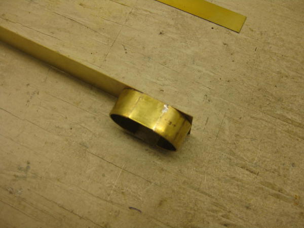
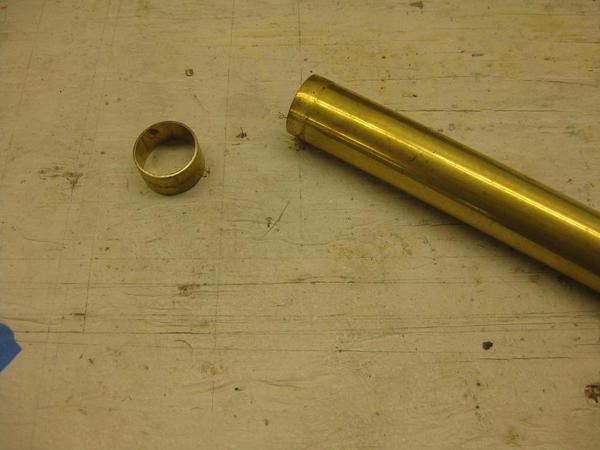
Using the brass tube from Online Metals, I cut a piece slightly taller than needed.  My big hands can't hold on to those little pieces and later I cut it down to correct dimensions (below).
 

IMG_6893


Here's how the the tube compared to the dome I was making, I couldn't keep the radius concentric on each end and kept making 'egg' shaped domes.  I'll try Bob's technique on the next project (below):


IMG_6894


I marked center OD of the tube and used tape to serve as a vertical cutting guide.  My saw quit so I used a razor saw...ugh.  After cutting the tube vertically, it 'relaxed' and was bigger than original (below).


IMG_6895


The brass sheet was the same width as my original tube diameter.  Hard to see in the picture, but I measured and scribed an equal distant line, equal to the tube radius on each end of the brass sheet. This aided in accurate placement of the tube and 'scaled' the dome to the correct length and width.  I used the Vise-a-grips to pull the tube back to the correct diameter for soldering (below).
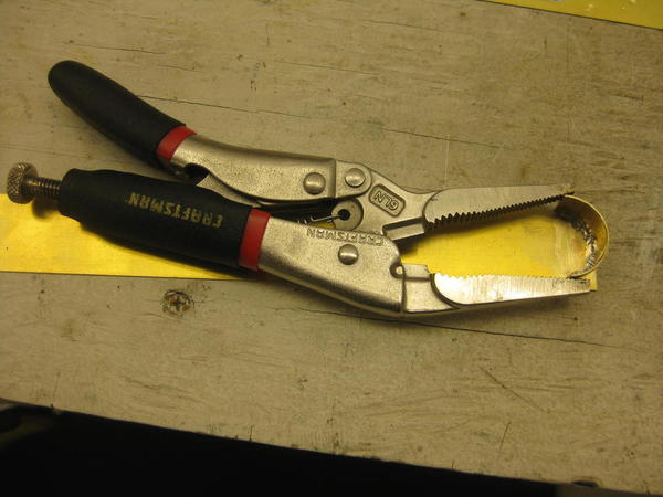
 

IMG_6896


My 'high speed press' I use to hold parts:
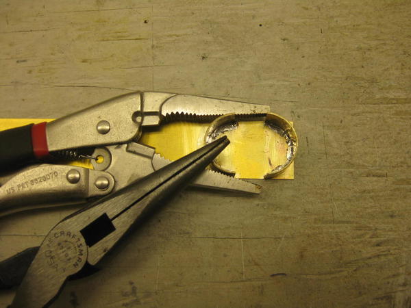
 

IMG_6897


The straight section of the dome soldered in place:
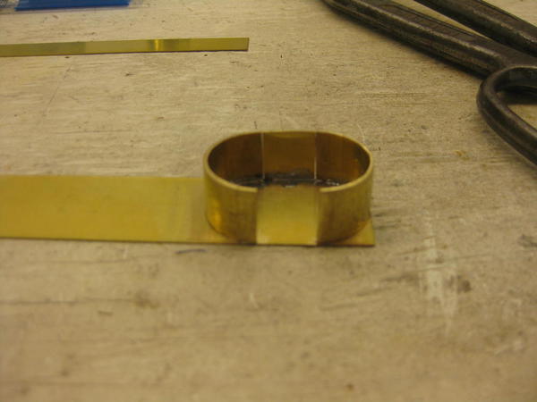
 

IMG_6898


The other side:


IMG_6900


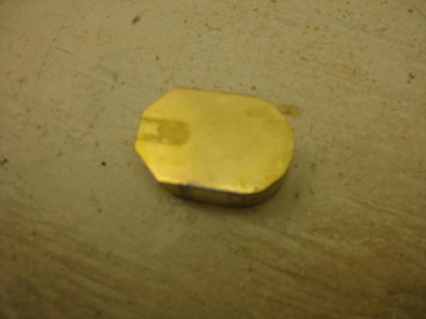
Cut dome from sheet and started rounding the corners:
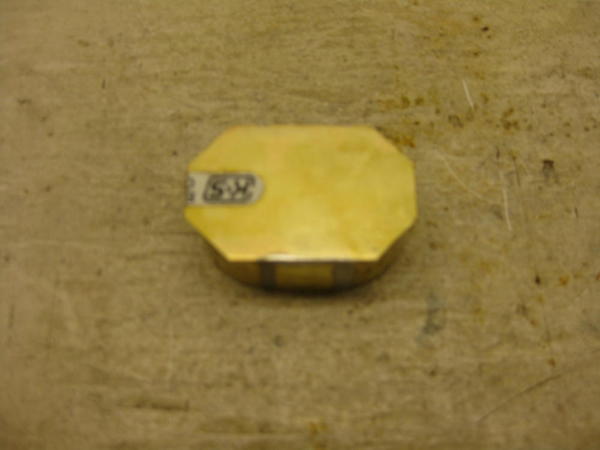
 

IMG_6901

IMG_6902


Scribed a line around dome and marked with tape to get the correct height.  Cut dome:
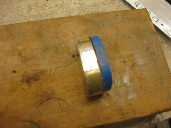
 

IMG_6903


Found center of boiler/dome and marked them for reference:
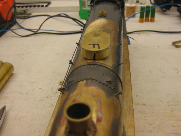
 

IMG_6904


Here, I started to profile dome to boiler using a cutting tool, anyone notice I missed something important? 
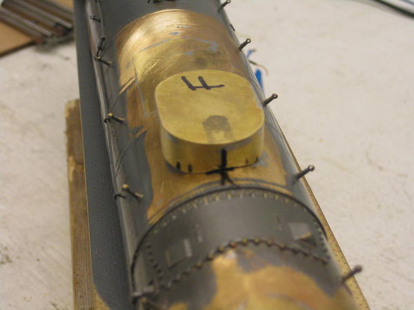
 

IMG_6910


Started on smaller second dome:


IMG_6911


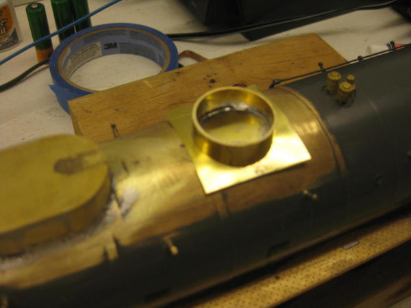
Profiled it and added the flange:


IMG_6912

IMG_6913


Rounded the edges of the flange:


IMG_6915

IMG_6916


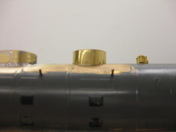
Second dome installed:


IMG_6917


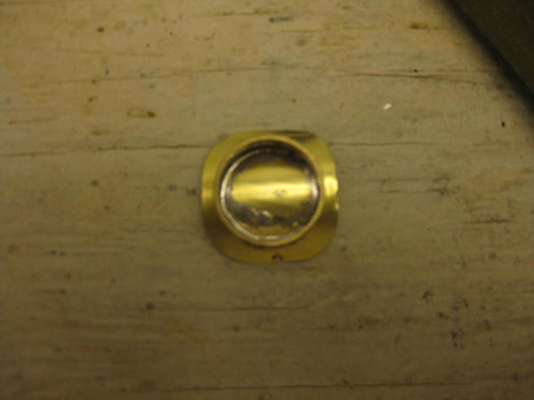
At this point, I was marveling at my work when I realized I forgot the flange on the first dome!


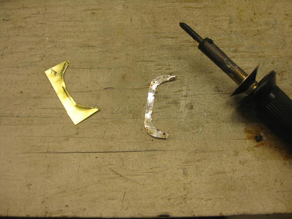
So, here's how I corrected it.  Using masking tape, I made a pattern and transferred it to the brass sheet.  I decided it would be difficult to make the flange in one piece and slide over the dome to fit, so I cut it in half.  Then cut out the marked section, filed to fit, and installed.
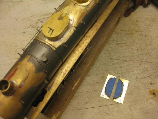


IMG_6918

IMG_6919

IMG_6920

IMG_6921


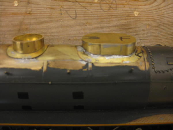
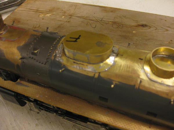
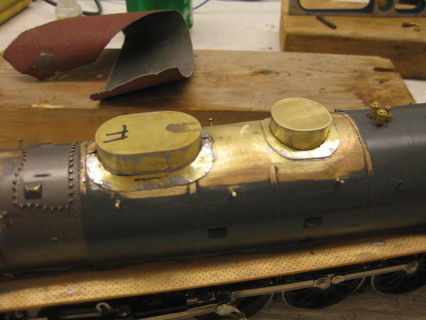
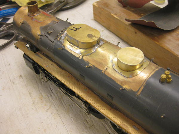
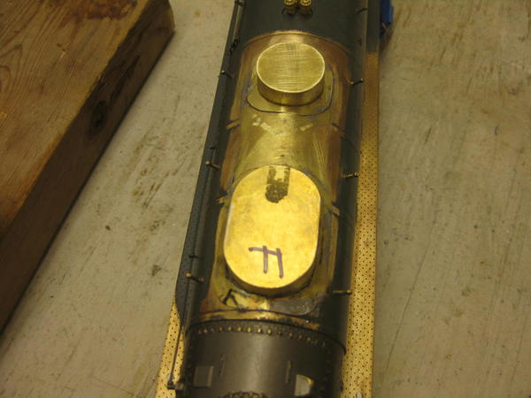
The final dome/flanges:


IMG_6922

IMG_6923 

IMG_6924


Learned a lot and tried different techniques.  In the future, I hope to have a lathe to do the round domes.  Also, I won't forget the flange again, it was a lot of extra effort to make it that way, but well worth it.  A little filler at the dome/flange transition and it'll be done.


I'm very pleased with the results.  As Ron said, sometime attempts 3-5 are just practice runs!


Firewood, not sure you're still following along, but thanks for the article.  I've printed it out and spent time reading it.  The techniques can be used in brass also.  It should help when I'm ready to do a complete scratch built locomotive.  


Now on to the detail parts and stuff I'm really looking forward to building.

Attachments

Images (25)
  • IMG_6893
  • IMG_6894
  • IMG_6895
  • IMG_6896
  • IMG_6897
  • IMG_6898
  • IMG_6900
  • IMG_6901
  • IMG_6902
  • IMG_6903
  • IMG_6904
  • IMG_6910
  • IMG_6911
  • IMG_6912
  • IMG_6913
  • IMG_6915
  • IMG_6916
  • IMG_6917
  • IMG_6918
  • IMG_6919
  • IMG_6920
  • IMG_6921
  • IMG_6922
  • IMG_6923
  • IMG_6924
Last edited by 86TA355SR

Double-check those flanges with some good prototype photos. There are good shots on page 111 and the back inside cover of Kratville's book.


The more I think about it, the more I would opt for solid brass on this model.  I built my sand dome the way you did, except I used a very thick top to be able to carve a radius between sides and top.  Boiler contour is the main problem, but is easily done with a new crosscut file and a sanding drum.  Then the attach is by a screw, greatly facilitating the addition, and trimming, of the flange.


Nice work.  I wouldn't even attempt doing a flange after the dome is attached - I don't have that kind of patience.

Dave,

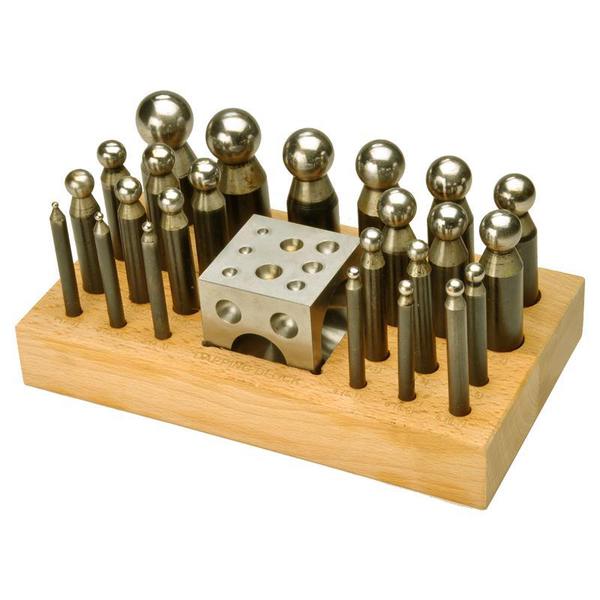
Where do I buy dapping blocks?  Hardware store?


Though I've done a lot of model building in resins and plastic, brass/metal is all new.  I'm slowly building a tool collection that makes life easier, I think I could use these blocks on many more projects.  Would be a worthwhile investment.  Plus, I like tools! 


Not a lot of progress to report on the FEF.  No parts have arrived and family arrives tomorrow, so it'll be a week or two before I get back to work on it.

No, I've been busy with other things since the last update.


Weekends have been full with family and I haven't had time to do much.  I was hoping to start on the rods last week, but it didn't happen. Probably next week, everynight this week is full and next weekend is busy also. 


I'm just a popular guy everybody wants to hang out with


I'll let you know when I get back to work!

Add Reply

Post

OGR Publishing, Inc., 1310 Eastside Centre Ct, Suite 6, Mountain Home, AR 72653
800-980-OGRR (6477)
www.ogaugerr.com

×
×
×
×
Link copied to your clipboard.
×
×