The front driver wheels are turning faster than the rear drivers. Anyone ever see this before? Is this a bad driver unit? Lionel Union Pacific challenger #3980 6-38093 with the old Odyssey system.
#


|
|
The front driver wheels are turning faster than the rear drivers. Anyone ever see this before? Is this a bad driver unit? Lionel Union Pacific challenger #3980 6-38093 with the old Odyssey system.
#
Replies sorted oldest to newest
Totally normal, that's how speed control works in a dual motored loco . When loaded on the track ,the voltage will even out.
Every Lionel diesel also reacts that way.
@RickO posted:Totally normal, that's how speed control works in a dual motored loco . When loaded on the track ,the voltage will even out.
Every Lionel diesel also reacts that way.
Oh wow! I thought I was onto something. I was thinking that was the cause for the runaway speeds this loco experiences. The little ring on the rear flywheel is intact. Could a runaway engine be because of the driver unit?
Runaway how? If it does not see the command signal it will power up in conventional - if there is 18v on the track it will take off at full speed. There are lots of guys that will help, they just need more detailed information as to what is happening.
@Darrell posted:Runaway how? If it does not see the command signal it will power up in conventional - if there is 18v on the track it will take off at full speed. There are lots of guys that will help, they just need more detailed information as to what is happening.
I can start up the engine with my Legacy remote and all lights and sounds work. Most of the time it will start out at normal control speeds but eventually it takes off fast like it was a conventional engine at full voltage.
The experts will need to chime in, but it might be something going on with the tach reader? Not familiar with the original odyssey cruise control. Sorry that I can't really help on this one.
As Rick O stated. It’s perfectly normal.
Check the wiring from the sensor board on the motor to the DCDS. It can also be the DCDS or the actual sensor board.
@gunrunnerjohn posted:Check the wiring from the sensor board on the motor to the DCDS. It can also be the DCDS or the actual sensor board.
Thanks so much! I will be looking into that this afternoon when I get home.👍
@gunrunnerjohn posted:Check the wiring from the sensor board on the motor to the DCDS. It can also be the DCDS or the actual sensor board.
I forgot to ask. If it turns out to be the DCDS, can it be replaced with an ERR cruise control kit?
@rscott521 posted:I forgot to ask. If it turns out to be the DCDS, can it be replaced with an ERR cruise control kit?
In general yes. You may have to deal with stuff like class lights that might be powered from the 10-pin connector on the DCDS, but you should be able to do it without too much issue.
@gunrunnerjohn posted:In general yes. You may have to deal with stuff like class lights that might be powered from the 10-pin connector on the DCDS, but you should be able to do it without too much issue.
Sounds good! I will look into that if I need one and ERR has them in stock. Thanks again.
*Update*
Got home and checked the things Gjohn mentioned. I cleaned the sensor board reconnected the associated connectors. I ran it around the track without the shell and it seemed to do fine. I put the shell back on and try to run it and the red light on my GW-180 is flashing. I remove the shell and find one of the gray wires to the front motor nicked. I repair it and remove all electronic boards from the frame and give it a go over. I reassemble everything but the shell and run it on my track. It runs forward fine but if I try reverse the red light again flashes on the GW-180. Bad driver board
Probably the motor drive FET's for the reverse direction, they can be replaced.
@gunrunnerjohn posted:Probably the motor drive FET's for the reverse direction, they can be replaced.
I'd like to try that. Is there a particular fet that I need? Could I get the part number off of the original and use that?
Yep, use the number of the FET. You can check with an ohmmeter, you'll find one or two shorted. I normally replace the pair.
@gunrunnerjohn posted:Yep, use the number of the FET. You can check with an ohmmeter, you'll find one or two shorted. I normally replace the pair.
Thanks so much! I will get on that in a few minutes.👍
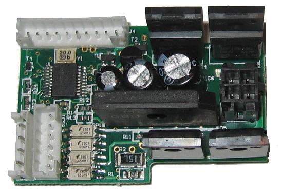
@rscott521 posted:Anyone know what this chip is circled in red? If I go for an ERR cruise control will this chip still be needed?
Appears to be a bridge rectifier that converts AC to DC. I assume you are going with the ERR cruise commander, if so the rectifier isn't required.
@rscott521 posted:Anyone know what this chip is circled in red? If I go for an ERR cruise control will this chip still be needed?
Tethered bridge diode rectifier pack.
They are used and mounted remotely like that because they get hotter under current draw and have higher reverse leakage when/if they get too hot.
So yes, ERR Cruise M has the bridge rectifier mounted on it- and yes- in certain applications- might need to be remotely mounted on long wires to chassis heatsinking for similar reasons.
@Vernon Barry posted:Tethered bridge diode rectifier pack.
They are used and mounted remotely like that because they get hotter under current draw and have higher reverse leakage when/if they get too hot.
So yes, ERR Cruise M has the bridge rectifier mounted on it- and yes- in certain applications- might need to be remotely mounted on long wires to chassis heatsinking for similar reasons.
So, if the ERR CCM has the rectifier already on it then do I need to remove the factory one?
The Bridge on Cruise M jammed in the middle http://www.3rdrail.com/err-3rd...ruiseCommanderM.html
And yes, in some cases, you unsolder it, then use 4 wires to remotely mount it.
@rscott521 posted:So, if the ERR CCM has the rectifier already on it then do I need to remove the factory one?
Well, my fault, I'm now looking at a detail of that specific bridge and it was not tied to the original motor driver.
NO, it is in fact being used to DROP voltage for something!!!!!

Notice the black wire is SHORTING + and - leads of the rectifier!!!!
Million dollar question- where and to what are the white wires going????
Again, this is being used clearly as a bi-directional AC voltage drop device, shaving off a few volts for some decent powered load hence the need to heatsink it to chassis.
One answer might be less voltage to the front motor without a tach reader?? I'm spitballing here but without knowing the circuit, without knowing where those 2 white wires exactly go and terminate.
@Vernon Barry posted:The Bridge on Cruise M jammed in the middle http://www.3rdrail.com/err-3rd...ruiseCommanderM.html
And yes, in some cases, you unsolder it, then use 4 wires to remotely mount it.
I think I get you now. You are saying remove the rectifier from the CCM board and remotely mount it? Correct?
@rscott521 posted:I think I get you now. You are saying remove the rectifier from the CCM board and remotely mount it? Correct?
In some cases yes, however you appear have a different situation. Go back and trace out those white wires.
@Vernon Barry posted:Well, my fault, I'm now looking at a detail of that specific bridge and it was not tied to the original motor driver.
NO, it is in fact being used to DROP voltage for something!!!!!
Notice the black wire is SHORTING + and - leads of the rectifier!!!!
Million dollar question- where and to what are the white wires going????
Again, this is being used clearly as a bi-directional AC voltage drop device, shaving off a few volts for some decent powered load hence the need to heatsink it to chassis.
One answer might be less voltage to the front motor without a tach reader?? I'm spitballing here but without knowing the circuit, without knowing where those 2 white wires exactly go and terminate.
One of the brown wires coming from the middle of the rectifier goes to the sensor board on the rear motor. The other brown wire goes to one side of the front motor.
@rscott521 posted:One of the brown wires coming from the middle of the rectifier goes to the sensor board on the rear motor. The other brown wire goes to one side of the front motor.
So as I said, they are using it as a way to reduce the parallel voltage being fed to the front motor for speed and torque matching or loading reasons. Again, that rectifier would stay in the circuit, it is between the motors for a reason.
Likely wiring diagram


@Vernon Barry posted:So as I said, they are using it as a way to reduce the parallel voltage being fed to the front motor for speed and torque matching or loading reasons. Again, that rectifier would stay in the circuit, it is between the motors for a reason.
Would an ERR CCM module work with this rectifier?
When the engine ran the front driver wheels turned faster than the rear ones. Is the rectifier doing that?
@rscott521 posted:When the engine ran the front driver wheels turned faster than the rear ones. Is the rectifier doing that?
The motors are in parallel. They BOTH got fed the same voltage and power from the original motor driver (it only has 1 output).
As stated several times in this topic- pretty normal to see 2 motors and drivetrains in parallel not perfectly matched- thus given the same power- they don't run the same speed. This is more a dynamic of the motors and drivetrains. While it would be ideal if they matched in the unloaded state, it's not a showstopper and often normal.
Further- your test was UNLOADED. Recognizing that, and understanding electronic components and ratings- as well as being able to read a component data sheet- one would know that diodes have a voltage drop curve that is NOT a flat line value. So, if the current is low- going back to this unloaded condition- then the voltage drop or loss or difference between the parallel motors is minimal. It's under actual track load and conditions, right before the wheels begin to slip- that's when the effects of this diode bridge are going to come into play.
Again, the fact is, only ONE motor has the tachometer feedback to the motor driver. Thus if it goes into wheelslip- the motor driver reduces overall voltage to BOTH motors to maintain the commanded RPM value- hence not good. That's why if on rollers and unloaded, and you load the tachometer motor down, the driver increases power to maintain RPM- at the same time- the front motor without a tach displays this rpm change as the power varies.
Again, if the feedback loop is on a motor or truck that is slipping, it just maintains rpm by reducing power- however, if that same power is being used on a second motor truck and that truck is or isn't slipping- it too gets reduce power- thus your train may stall forward motion and only one truck or power wheelset- the one with the tachometer maintains rpm but is in wheelslip. Conversely, if that same motor with the tach has better traction- the feedback says give more power to maintain RPM- both trucks (the tachless one too) gets more power to maintain the desired speed.
In an ideal world, more like an advanced real train, each wheelset and motor would have feedback and an individual motor controller and thus the maximum power- right up until wheelslip could be applied- but that's not practical in the model world at the moment.
This is a wealth of information for me. Thanks!

Access to this requires an OGR Forum Supporting Membership

