Anyone experimented with tach stripe spacing smaller than the 0.050" in John's PDFs?

I put the 0.050" ones on a couple of my diesels, and I love the result. Very smooth startup now, compared to stock. They run about 2/3 the indicated speed now, but that suit me just fine, as I tend to run quite slow on my layout anyway. It really gives me more speeds steps in the range I want to run, and I get to hear the engines rev up more!

So I want to try another tach tape on my Alco switcher, and I figured experiment a bit and see how low I could go.

John, if you don't mind sharing, how did you generate those tach stripe images?

Thanks!


Original Post

Replies sorted oldest to newest

When I put in a tach tape with too small of stripes, some were ignored and I believe it started counting like every third stripe. I got a result that was opposite what I wanted. I think you can also adjust the flywheel diameter to change the speed. So a certain thickness of stripe would pass faster or slower?

It was a long time ago and I didn't make notes. There was a post here from Dave Hikel, on the limits and what works with the stripes. I'll search for it.

There is a limit, and it's dependent on the maximum RPM and the stripe width.  Also, if the stripes are not true black with bright white, it will reduce the reliability.  I've gotten down pretty small and still had reliable operation, but I also never actually took notes.

One thing to try, moving the sensor slightly in and out, that will make a big difference in the sensitivity.  Here's a sensitivity chart of the sensor I use on my Chuff-Generator, the MTH tach sensor is very similar in response.  Note the sharp peak at around 0.6mm that starts falling off about 10% by the time it gets to 1mm.  By the time it gets to 2mm, it's way down to 40% of the sensitivity.  That's why the spacing is so critical.

Wait, I found the PS/2 sensor curves, so here they are, the sensor is the Omron EE-SY124.  They are marginally less sensitive to distance, but still pretty touchy.  Around .7-.8mm would be the optimum spacing for maximum sensitivity.  I also think they stacked the deck with the sensing surface, looks like they went for the ideal.  The QRE1113 above used a more realistic 90% reflective white paper as the sensing material.

Attachments

Images (2)
  • mceclip0
  • mceclip1
Last edited by gunrunnerjohn

Thanks for the info, guys!

I printed some tach stripes from 0.050" down to 0.025". I used Avery weatherproof shipping labels and a laser printer, which gave nice sharp stripes, and confirmed the actual spacing with a caliper. Here are the results so far:

  • 0.025": Didn't work. The engine took off from a stop to a modest but more or less constant speed. In light of the results with the 0.035" spacing, I'm not really sure why this didn't work at least at low speeds - the time interval with the 0.035" at high speed is far smaller than this one at low speed. But, that's the way it was.
  • 0.030": Worked, but seemed marginal, with occasional slight surges.
  • 0.035": Works fine. Starts, stops, and changes direction really nice and smooth. Ran it up to speed step 75 without issue. I need to change my accel and decel settings though - since the decoder thinks its going faster now, it takes a loooong time to stop.

For now, I'm going to run like that, and will report back if there are any issues. It certainly had the desired effect - it runs almost as slowly and smoothly now as my ESU-equipped Atlas SW9.

Here it is with the 0.035" stripes on speed step 3:

Attachments

Videos (1)
IMG_8313

it did not hit me just how small he's going with these stripes. I just went down to look at some of my tapes and it really set in. First, I was looking at metric when he's describing inch measuring. I really can't believe that .035" works at all?

I've never gone anywhere near that small. To make things even more startling to me, my stripes seem to have wider white than the black itself. I measured my .050" stripes in black and the white spaces are closer to .070"! So I can only guess that the laser printer quality is much better, the spacing is perfect, or something similar to get these small stripes to work?

WOW!

Last edited by Engineer-Joe

What you want are better motors and a control system as well. Not happening that I can tell. All the motors I have from diesels I pulled out of are those mabuchi things. If I apply low voltage to them, they spin poorly.

I also don't understand why they don't spec motors with built in encoders as they appear to be widely available.

So I got curious(er) did a little more digging on my SD45, which was the next one up for a new tach tape.

The tach sensor has some logic built in, probably similar in principle to the one I described here, which I used in my Arduino turnout project. It looks for a change in reflectivity of the tach tape, and outputs basically a yes/no signal to the processor. Unlike the one I mentioned, however, there seems to be one key difference with this sensor - it requires an active transition from say, black to white, in order to output anything. So if I spin the flywheel slowly by hand, the output of the sensor never goes high, even as both black and white stripes pass under it. If I spin it faster, then I see the output going high and low as you would expect. I think this plays into the minimum stripe size, as you'll see below.

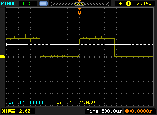
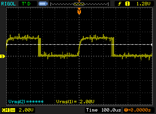
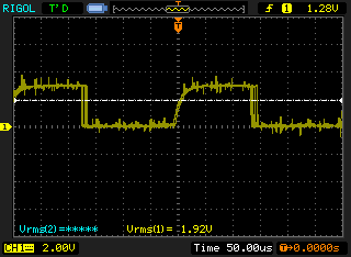
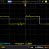
Here is the response of the sensor at speed steps 5, 10, 50, and 100 with the stock stripes:

speed 005speed 010speed 050speed 100

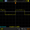
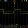
A couple points to note. The period of the pulses corresponds linearly to the speed setting. That is, for example, at speed 10, the period is right about at 3ms. At speed 100, the period is 300us. So to the processor, a 3ms period is speed 10. It doesn't matter what the actual width of the strip is, which is why I was curious as to why there was a minimum limit.

Also, the curved rise in the signal is present at all speeds, it's just not evident in the speed 5 and 10 screenshots. So it's not simply a case of the signal degrading at higher speeds.

Here are speed steps 10 and 100 with the 0.050" stripe tape:

speed 010speed 100

So far, so good. Looks exactly like the shots with the stock stripes.

Here's a couple screenies with the 0.030" tape:

speed 010speed 100

In these shots, you can see that, although the period is generally the same as with the stock and 0.050" tapes, there is quite a bit of variability in the response. I think we are right near the limit of the sensor, which is subjectively consistent with the results I saw on the Also - it ran, but just.

Then I tried the 0.025" stripe tape, and got - nothing! No output from the sensor at all. Moving it by hand as slowly as I could still produced no output. I think what is happening is that the stripes at that point get close enough together that the sensor is no longer able to discern a transition, at any speed, and so there is no output. So that's why 0.030" works, and then, suddenly, 0.025" doesn't work at all.

So it looks like even if the stripes are really sharp, at around 0.025" width, the sensor is not able to identify discrete transitions, and generates no output.

Attachments

Images (8)
  • speed 005
  • speed 010
  • speed 050
  • speed 100
  • speed 010
  • speed 100
  • speed 010
  • speed 100

I use a laser printer and print my strips on gummed 1/2 page shipping labels.  I use the "label" setting to get darker and clearer prints.  I've never tried to go anywhere close to .025 for the stripes, the stock MTH stripes are .07" wide on the 27mm flywheel image, that's the smallest stripe they use.

The Fairchild QRE1113 has this nice diagram of the emitter angular displacement, that helps to understand the minimum size strip that can be sensed.  I suspect once the strip is well under the spread of the emitted IR beam, the sensor is simply picking up the reflection off the  white on either side and not seeing the black at all.

Attachments

Images (1)
  • mceclip0
Last edited by gunrunnerjohn

I made my own with some adafruit parts and I stole a circuit off of some website I found for ir detection. I used silver duct take to make two big reflectors on the motors flywheel. The resulting voltage drop and rise is big enough I can plug the output into an interrupt pin on an arduino and count pulses. My calculations appear to align with the scope. If though I go for the motor with neatly packed black and white lines, I get a poor voltage drop. Although on the scope it's clearly detecting the lines. As I understand it it's possible to add some logic to make nice square waves... a suggestion is a Schmitt trigger or perhaps some custom logic.  I have not gone there yet because I can't see that it matters in my efforts. On the power side  I'm using a motor controller from polalu called the jrk g2.  It got a lot of features, more than I need I think but I bought it months ago out of this context.

It might be helpful to underscore that I have no idea what I'm doing. What's taken me weeks could be done in an afternoon by a knowledgeable type.

What I'm moving to next is getting power from the track. I'm just thinking about that now though.

If I get that working even in a simplistic way I'll go back to writing software.  The arduino has a pid controller library and I'll fiddle with that, just for example.

I'm trying to write my own engine controller for fun. Anyway I am seeing squares for the 2 reflective panels I applied but not so square for the multiline version. Again I suspect a bit more logic could do it but I'm not going there yet since I don't have any reason to do it. Finally I'm happy to post a pic of my setup but I'm not near it at the moment.

But its all just for fun. I considered various ways to tach the motor. I failed at the first way which is back emf. I could not get that right. 

I considered slots or magnets but the ir seemed simplest.  

As I said I could just buy a motor with an encoder built in but it would not have the worm gear on it.

Etc...

Engineer-Joe posted:

WOW! That was thorough. Thanks.

If you felt like it for fun, could you try a tach tape printed with a normal printer?

I only ask as I'm thinking the laser provides better quality and is easier for the reader? Myabe my tapes aren't producing sufficient results so that I can't go that thin of stripes?

I was going to test that as well, actually, just to see if there was a difference in response between the laser and inkjet printed stripes. Then I discovered my inkjet printer bit the dust a while back. 

I did notice in looking at the responses above, there is a slight difference in the ratio of on/off times with the tapes vs. the stock stripes. For instance, with the stock stripes at speed 10, the on time is about 1.4ms. With my 0.050" tape, it's more like 1.2 or 1.3ms. The total period is the same, though, at 3m. It's hard to say at what point that would start to have an impact on the processor. It's probably just triggering on the rising signal, which would make it fairly insensitive to the width of the black vs white.

Just judging by eye, the stock stripes don't really look particularly precise. I wouldn't be surprised if the printed stripes are more uniform.

gunrunnerjohn posted:

I use a laser printer and print my strips on gummed 1/2 page shipping labels.  I use the "label" setting to get darker and clearer prints.  I've never tried to go anywhere close to .025 for the stripes, the stock MTH stripes are .07" wide on the 27mm flywheel image, that's the smallest stripe they use.

The Fairchild QRE1113 has this nice diagram of the emitter angular displacement, that helps to understand the minimum size strip that can be sensed.  I suspect once the strip is well under the spread of the emitted IR beam, the sensor is simply picking up the reflection off the  white on either side and not seeing the black at all.

Yeah, it would be interesting to play around with some different sensors and see if you could get a signal with smaller stripes. But I'm not sure it would be that interesting...

I would tend to think the stripes per wheel is a constant in their calculations...  I guess I haven't ferreted out why for example more stripes would be better if you -- or that is they -- don't really seem to make much use of it.   From admittedly 5 ft away, it appears to me that even at slow speeds the motors turn fairly fast -- what do you stripes give you if you don't want or can't know about partial wheels turns?  maybe the running avg hz is better perhaps...

The factory tach tapes for MTH have 24 stripes.  However, that's because they know what the gear ratio is.  With non-MTH locomotives, the gear ratios can be all over the map.  I've done some brass locomotives lately with much higher gear ratios, so 24 strips runs them way slower than the indicated scale MTH.  If you reduce the stripe count, they'll run faster because the speed control is simply count stripes.  If you increase the stripe count, they'll run slower.  You can adjust a non-MTH locomotive to run at the indicated scale MPH by modifying the stripe count on the tach tape, that's why you'd go to the trouble.

Add Reply

Post
The DCS Forum is sponsored by

OGR Publishing, Inc., 1310 Eastside Centre Ct, Suite 6, Mountain Home, AR 72653
800-980-OGRR (6477)
www.ogaugerr.com

×
×
×
×
Link copied to your clipboard.
×
×