Now I remember why I had to go to school to get my Master Electrician license.  We learned to read and understand this stuff.  Here is the official NEC info in detail.


Page 70-270  National Electrical Code 2011 Edition
Article 406 -- RECEPTACLES, CORD CONNECTORS AND ATTACHMENT PLUGS (CAPS)

406.4(D) Replacements. Replacement of receptacles shall comply with 406.4(D)(6), as applicable.
(1)~~~~~~~~~~~~~
(2) Non-Grounding-Type Receptacles.  Where attachment to an equipment grounding conductor does not exist in the receptacle enclosure the installation shall comply with (D)(2)(a), (D)(2)(b), or (D)(2)(c).
   (a)  A non-grounding-type receptacle(s) shall be permitted to be replaced with another non-grounding-type receptacle(s).
   (b)  A non-grounding-type receptacle(s) shall be permitted to b replaced with a ground-fault circuit interrupter-type of receptacle(s).  These receptacles shall be marked "No Equipment Ground."  An equipment g5rounding conductor shall not be connected from the ground-fault circuit-interrupter-type receptacle to any outlet supplied from the ground-fault circuit-interrupter receptacle.
   (c)  A non-grounding-type receptacle(s) shall be permitted to be replaced with a grounding-type receptacle(s) where supplied through a ground-fault circuit interrupter.  Grounding-type receptacles supplied through the ground-fault circuit interrupter shall be marked "GFCI Protected" and "No Equipment Ground."  An equipment grounding conductor shall not be connected between the grounding-type receptacles.


Original Post

Replies sorted oldest to newest

You need to understand the problem that exist when a 3 prong grounded type outlet is used as a replacement for old wiring two prong non-grounded outlets. One assumes the third prong is functional, when it in fact is not.  This section of the code addresses proper replacement of worn-out two prong outlets.  There is a lot of liability related to improper replacement of old two prong receptacles.  

2.(a) Replacement with a similar, like-kind, (2 prong receptacle.)  Yes, you can still buy two prong receptacles and it is permitted to replace them.  I uses to carry a few in the truck.  

2.(b)  You can replace (2 prong receptacles) with a GFI (Ground Fault Interrupter) receptacle, and there is a good chance that the note required is in the box of material. "No Equipment Ground"  Ground fault receptacles will work without a ground wire present and in most cases work well.   

3.(c)   Notes a circuit where a GFCI (Ground Fault Circuit Interrupter) breaker is install in the panel to protect the entire, old, two wire without ground circuit. .  You still have to install the "No Equipment Ground" note and "GFCI protected" note, on each device protected.

Properly done all lawyers should be happy.  

Mike CT 

Safety meeting of the day.  Thank you, Susan.    

Last edited by Mike CT

I have to ask after reading the surge arrestor thread why one would recommend that a individual not use a 3wire replacement cord and a grounding type plug when they are replacing both the plug and cord on a PW ZW transformer. This is clearly covered under 250-4(A)(3)

Am I missing something here?

I've been in the trade 31yrs now and I can't think of one reason why I would recommend that someone that is replacing both the cord and plug of a PW ZW, continue to use a method which would leave metal current carrying parts not effectively bonded.


Scott

Originally Posted:

I have to ask...  ...why one would recommend that a individual not use a 3wire replacement cord and a grounding type plug when they are replacing both the plug and cord on a PW ZW transformer.

Is there some portion of 250-4(A)(3) that allows for the green ground wire to be left unconnected, and if not, where would this connection take place in a ZW?

Rob article 250-4(A)(3) does not specify a green wire, but rather that metal parts must be effectively bonded. I'm not a code expert, however I'm not aware of anything in that portion of that article that would exempt you from not bonding a exposed metal part. If a ground fault occurred and it was not effectively bonded with a path back to the source I'm not sure how the OCPD could properly perform its task.

I've been thru 100's of inspections on both sides of the coin and I can tell you unless it's double insulated(which PW ZW's are not) not bonding a exposed metal part is a sure fire violation.

 As far as where to connect the bonding conductor, IMO any portion of the metal frame would be suitable. 

 Scott

Originally Posted by Tryanst 1880E:

...As far as where to connect the bonding conductor, IMO any portion of the metal frame would be suitable.

This is the problem.


Nobody in their right mind is going to ground the chassis or baseplate of a ZW. If a secondary wire breaks or fails and/or contacts the grounded chassis or base, you are asking for real trouble on a toy train layout with the voltage potential(s) involved.

Having read all the threads also.
I try to refrain from responding to threads are a mostly emotional based on false beliefs.

Bonding to the metal chassis provides a path in the event of primary short. The reasoning that a life is more valuable than any toy train.
Combined with a properly functioning GFI outlet you now have a safe electrical device with a high current potentional. Great for that rare occasion when a guest spills an entire beer on your ZW.
I am also pretty sure that a secondary short inside would immediately trip the internal protection and or pop the GFI. Not muck different than a sort on the track.
Or you can remain a "purist" and operate your chainsaw without protective chaps, gloves, eye protection and hearing protection. Still not sure why I replied. I guess if you lead enough horses to the trough, maybe one will drink. Jmho.
FYI.
I am also the internal UL coordinator for our sigh company. Well versed in UL and NEC as applied to lighting.
And our UL inspector is a fanatic when it comes to inspecting proper bonding methods.
Like not using component mounting screws, proper serated washers, etc....
Most Led power supplies are very similar to train transformers. And the usually are double insulated also.
Still a green bonding wire to the metal enclosure.
Every time. No exceptions. And absolutely not valid reason not to.

Note again that GFCI protection will work without grounding/metal case/shell grounding installed. If there is a leak to ground, ( Assume that to be through you, since there is no safety ground path present) the threshold trip current is about 5 milliamps.  You can purchase GFI protection as a cord end add device.  Every truck/electrician, that I was responsible for, had one and was required to use it.  As time evolved large capacity battery powered tools became the norm.


In reference to old electrical equipment. IMO there come a point when it should be recycled.

Safety meeting of the day.

Last edited by Mike CT
Originally Posted by Penn-Pacific:

So, these shouldn't be used, eh?


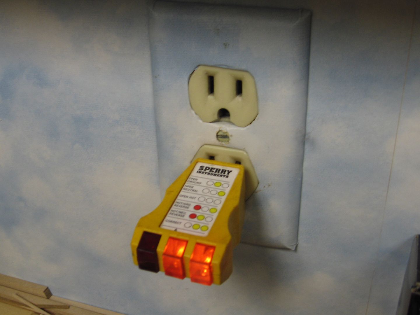
The device picture was designed for wiring 1950's through early 1960's that had grounding available at the outlet box even though there was no third prong available via the outlet.  It assumes that the metal box, in which the receptacle is installed, is grounded and that the face plate screw is also grounded. The face plate screw was to be remove and re-installed through the metal loop at the bottom of the adaptor. A lot of ifs.  There are testers available.  Surprisingly I use mine a lot.

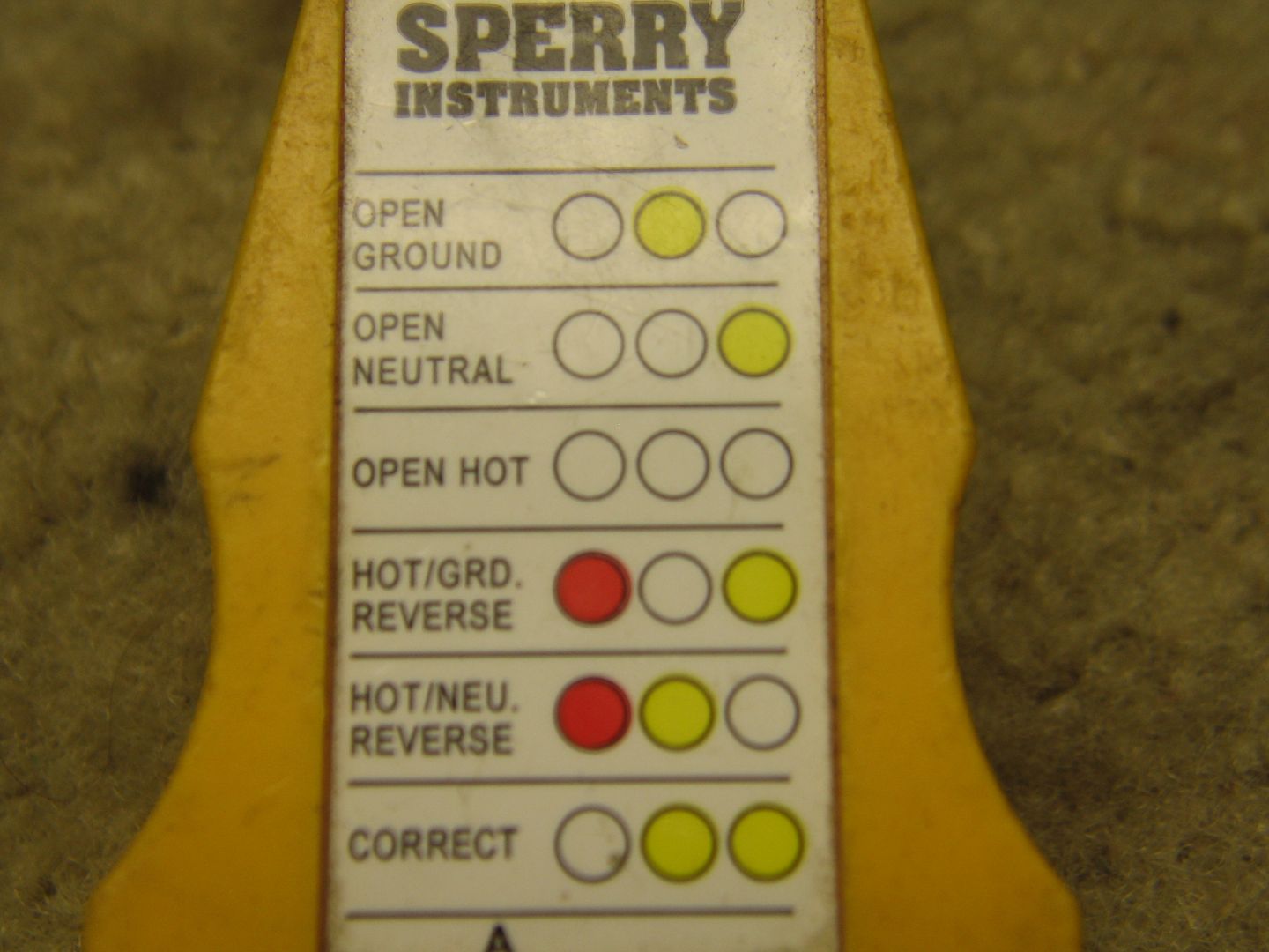
Note that middle and right lights indicate proper grounding/wiring. 

Note that I have seen receptacles wired, where the neutral connection was jumper-ed to the ground screw to get the correct indication on this device.   Shouldn't be.


Last edited by Mike CT

Can't be done with this device. If the neutral and ground are reversed you would get a correct reading.  Ground and neutral are eventually wired to the same buss bar in most electrical panels.  Distinction is: neutral is current carrying conductor and the ground is a safety non-current carrying conductor both at the same potential, hopefully 0 volts.

Originally Posted by Ffffreddd:
I believe ground goes to ground as in earth. Usually via a metal rod in the ground or a water pipe. Jurisdictions vary.
And what few people know is that the local building inspector has final authority over both UL and NEC it is also allowed to interpret the state code also.  Never **** himor her off.
Both the grounding system/wires and neutral wires are connected in most electrical panels. Both the grounding system and netural system are attached to some system of earth ground.  Minimum proper rods (2) 1/2" copper clad X 8ft. driven 6 ft. apart. (required). There are also proper brass attachment connectors, in most cases #4 solid bare copper to the rod(s).  The attachment to the water system is in most cases is considered a bond, in that, most metallic water supply systems are now non-metallic, as is most plumbing in newer/or remodeled homes. 
There is a ground potential test that can be done on a rod system to assure it's effective.  Often done on commercial installations, a little more that just an ohm meter test.  Point to be noted is that driven rods don't necessarily supply a good ground.  Multiple rods increase the reliability of the ground.
i.e. Cell tower sites several years ago, that I worked on had at least (10) 3/4" X 10ft rods driven all over the site. Then cad welded together with #2 solid copper wire.  Potential test required, looking for very low resistance. If it didn't meet specifications, you were driving more rods.  


Last edited by Mike CT
Here's to a link to a good article explaining grounding systems. The important part is this last paragraph.

"The last point that you should consider, is that every single electrical standard has been increasing its requirements for grounding and earthing systems year after year.  These standards have been written by very smart people and there are many reasons for the increased requirements.  It would take a long time to get into all of them, but the reality is that electrical system that have excellent earthing systems, function better than those that don’t."

http://www.esgroundingsolution...ng-electrical-system
Hi Mike,
I am aware that grounding buses and neutral bus are bonded in the main panel. In subpanels they are required to be isolated. With a separate neutral and bonding wire going back to the main. And yes that test me to does have a flaw in that if the neutral and ground I reversed it will still read correct.  But that does not mean that they should be interchanged. Or that they are equivalent. One is a return.  Yeah there is part of a grounding/earthing system. Part of the discussion of whether it makes sense to add a bonding wire on a corgi placement for an old ZW. I say it does make sense. And done probably this absolutely no reason not to.
Originally Posted by Tryanst 1880E:

I have to ask after reading the surge arrestor thread why one would recommend that a individual not use a 3wire replacement cord and a grounding type plug when they are replacing both the plug and cord on a PW ZW transformer. This is clearly covered under 250-4(A)(3)

Am I missing something here?

I've been in the trade 31yrs now and I can't think of one reason why I would recommend that someone that is replacing both the cord and plug of a PW ZW, continue to use a method which would leave metal current carrying parts not effectively bonded.


Scott

Scott, a power electrical engineer could give you a more accurate technical reply than I can.  My history with postwar ZWs, residential electrical systems, grounding, clothes dryers, and power may clarify.

*Postwar ZWs are not designed for a case ground (green wire) that would be separate from the neutral (white wire).

*Electric clothes dryers used to be designed for 3 prong plugs (green and white tied together which caused a shock hazard)

*Electric clothes dryers now must have 4-Prong Cords and sockets.  The case ground and the neutral must be wired separately.

*120/240 V wiring systems now require that the neutral and ground stay separated after the main electrical panel.  (for people safety and to prevent noise from "ratty" power)


Last edited by Susan Deats
Hi Susan,
I understand why the neutral and bonding wires should be isolated outside the panel.
Unless you are saying that all of the metal inside a postwar ZW is connected tothe white wire, than i can not see how adding a bonding wire will cause any issues. The bonding wire does not add noise but actually drains off unwanted corrona fields, static buildup and other unwanted stuff.
Without looking at one, my guess is that it is a simple variable step down transformer using a wound core. ( core and coil) These are typically attached to a metal bracket and mounted directly to a grounded panel. Similar to a 24vdc doorbell transformer.
Hi Susan, the 3prong to 4 prong issue does not really apply.
The 220acv 2- leg ( sometimes called 2 phase with a neutral bonded to the metal case is relatively safe. When it was realized that using 120v for other circuits like lights and timers, that the issue came into play.
With no 120 return the case became potentially dangerous.

See explanation

The three prong plug has two hot legs for the two bus voltages to add up to 220 volts, plus a neutral wire. Prior to 1998 the neutral was also grounded to the dryer case. A four prong plug has the two bus connections, a ground, and a neutral return. Often these are used if the dryer circuit requires 120 volts at some point, the current would flow from one bus and return through the neutral. If you were to change from a four prong to a three prong and your dryer is designed to use 120 volts at some point, then that current will have to be returned on the ground leg. This is not acceptable by NEC code, nor is it safe. If the 120 Volt circuit were to short, the full 120 volt potential could be present on the dryer case! Imagine touching the dryer at that time, and maybe on a wet floor!

On the cord replacement for a post-war Lionel ZW transformer, the proper procedure is two-fold.  This transformer cord should remain the two-wire cord with the two-prong plug.  The plug should remain the unpolarized type with both blades narrow (permits proper phasing when more than one transformer is used on a layout).  The second part of the proper procedure is that this transformer should be plugged into an outlet protected by a GFPP (ground fault personnel protection) device.  It is this GFPP device which provides protection from the exposed metal base.


I have some experience in the matter, and this is the only way compliance with the NEC (Code) can be achieved.  Ducking the incoming, I will explain why in a following post.  (Dinner calls...)


Frank (wearing P.E. hat today)

Returning to the subject, the issue with a toy train layout is that all the devices connected with it should be in compliance with the requirement that isolation from both sides (hot and neutral) of the 120-volt house circuit be provided on the layout.  Since the green grounds are connected in the panel box to the neutrals, the green ground is equally hazardous as the neutral wire, in this requirement (that is, it is half of a potentially deadly 120-volt circuit).


In addition, the green ground can (during certain faults not immediately corrected due to certain deficiencies in breakers or wiring) carry certain elevated voltages.  The obvious example is a dead short in the receptacle outlet, to the box if metal, that is not cleared by the breaker.  Half the drop will occur in the hot wire, and half in the green ground.  Thus this ground will become 60-volts ac hot at the outlet.


This is twice the permitted touch voltage of 30-volts ac on the layout (or on any electrical terminal which can be touched, such as bell or thermostat circuits).  The corresponding peak voltage matters, it is 42 volts.  At the time (long ago) it was thought to be equivalent to 42 volts DC.  At that time, the lowest DC voltage known to be dangerous (by experience) was 44 volts DC.  It is now believed to be a more complex relationship, but the standard has been unchanged to this day; it may be slightly conservative.


The highest voltage a PW ZW can produce is 28 volts* (there was a short run of a version which had an 8-volt coil in place of one of the 6-volt coils; I don't know if this version could have produced 30 volts).  The Z-4000 maximum is 28-volts; I am given to understand that it has a continuous maximum of 28-volts regardless of setting.  This is the primary reason to always phase transformers when using more than one of them.  (*Remember to add 1-volt to the marked 20-volts because of the ca-1954 change from 115v to 120v in household service; and to add 1-volt for the 5% permitted system over-voltage: all in addition to the usual 6-volt boost for the whistle motor.)


I can provide some examples of the ways in which ground wires become electrified; an example of serious consequences from this (on a subway platform); examples of household breakers not clearing a short (not unheard of); and explain the convoluted way in which the Code technically doesn't allow a ground wire to be added to the PW ZW cordset.  Finally, I need to agree with a statement above that a GFPP (or GFCI as you prefer) functions equally well in either grounded or ungrounded circuits and is on balance the better choice, particularly if two are provided in series.  In contrast, the ground wire is of use only if it can effectively trip the breaker on the circuit-- a problem with which the NEC has grappled with for over 50 years, and which still remains a work in progress.


I cannot provide any examples of serious consequences from toy train voltages.  That is one of the reasons why we are permitted our 10 amp outputs and large amounts of power in single devices.  The attention given here to proper phasing is a major contribution of this board.  We should all strive to keep it that way.  Hopefully I have contributed a little to the understanding of some of the other issues.


--Frank

hi Frank,
You added to additional information to the discussion. Thanks.
But you start off by stating that your understanding is the proper way and then do not actually make a logical case for why.
No offense. But your argument would not pass muster in a high school debate club.

Explain again how the possibility of a ground or bonding wire to become energized makes it "improper" to bond the ZW to ground but does not apply to other appliances.
You would need an energized green wire, a dead short of the secondary to the metal chassis, all of your protection devices to fail and not noticing that your conventional trains are zipping around at warp speed due to the 60volts or are all laying on the floor due to high speed derailments.
I think you need to make a stronger argument to convince me. Acting as an EE for the day is not the same as the real McCoy.
Hi Mike,
I agree with you on that point.
Except postwar switchers.

And I never understood this fascination with the old ZW's
I do not think they even have bell buttons. Lol. There are so many better options.

I also do not understand how knowlegable people can perpetuate mistaken concepts about electricity. A little common sense and the basic knowledge of electricity is all one needs to make good safe decisions when it comes to wiring.
I guess these beliefs need to be discarded. Unlike the old ZW the are not worth recycling. Not even any copper wire in them to scrap.
Originally Posted by Ffffreddd:
hi Frank,
You added to additional information to the discussion. Thanks.
But you start off by stating that your understanding is the proper way and then do not actually make a logical case for why.
No offense. But your argument would not pass muster in a high school debate club.

Explain again how the possibility of a ground or bonding wire to become energized makes it "improper" to bond the ZW to ground but does not apply to other appliances.
You would need an energized green wire, a dead short of the secondary to the metal chassis, all of your protection devices to fail and not noticing that your conventional trains are zipping around at warp speed due to the 60volts or are all laying on the floor due to high speed derailments.
I think you need to make a stronger argument to convince me. Acting as an EE for the day is not the same as the real McCoy.

Your sarcasm regarding Frank's EE credentials is unnecessary and rude. Anyway you are protesting too much in your redundant arguments. Time to stop this thread.

Last edited by Dewey Trogdon

"... a dead short in the receptacle outlet, to the box if metal, that is not cleared by the breaker..."


Well that's interesting. Why have a breaker if it doesn't do its job. The whole reason you have a breaker is to trip on a dead short, and is why you connect the ground system to appliances. So that the breaker will trip.

If it doesn't trip, then that's a breaker problem...and the fact that you designed the system for safety and part of it did not do its job.

Last edited by cjack

You do experience grounding, (non-energized safety wires), that becomes energized. It's part of the service electrical industry.

Example a few years ago.  Cable TV technician was hooking an internet modem to a customers computer. POW!!.  When I got to the home, there were arc/spark marks on the back frame of the computer.  Apparently the frame/shell of the computer was energize, 110 volts, and the cable/internet connector was grounded.  Older, reduced ground size wiring in the home.  At one time, 16 gauge wire was permissible grounding, non metallic sheath cables were manufactured and supplied with reduced size grounding wires.  An hour of service time, I found the ground wire for the questionable circuit, burned off in the electrical panel. Further investigate lead me to a light fixture, in another room, that the owner had installed, a few weeks earlier.  There was a short in the light fixture installation, that cleared, when the small ground wire burned off in the electric panel, causing further problems at the computer/modem connection.  So be careful, out there, there is still a lot of functional wiring that dates to before you and I were born. 

Second safety meeting of the day.   

Last edited by Mike CT
Originally Posted by cjack:

"... a dead short in the receptacle outlet, to the box if metal, that is not cleared by the breaker..."


Well that's interesting. Why have a breaker if it doesn't do its job. The whole reason you have a breaker is to trip on a dead short, and is why you connect the ground system to appliances. So that the breaker will trip.

If it doesn't trip, then that's a breaker problem...and the fact that you designed the system for safety and part of it did not do its job.


Circuit breakers do fail, and, from a service point of view, fail often.  Fortunately, most failures are to open, the circuit just doesn't work.  But there are failures the other way, a more serious safety concern. 


Last edited by Mike CT
Hi Dewey,
frank never claimed to be an EE.
He said he was wearing a PE hat for the day.

And my augment is not a "protest".
And reiterating the same thing is not redundant.
You may want to read the illustrated book of bad arguments.
I was pointing out Frank's logical fallacies.
Stating something is "proper" without reasoning to back it up, does not make it correct even if you have a PHD in physics.
So you want to stop the thread why? So the people " you" think are correct get to post their beliefs. Give me a break. You are the one who is "rude" for dismissing my position without any idea of what my credentials are.
Hi Frank,
I appologize if I hurt your feelings and came across as sarcastic.
It was intended to be dry Engineering humor.

I am disengageing.
I have violated my New Years resolutions not to engage in non productive discussions on this forum.  My bad.

I really do not care if anyone wants to put OEM cloth insulated cord on their ZWs and restore their house wiring to the original ungrounded uninsulated knob and tube.
Have fun.
Back to running my trains.

Add Reply

Post

OGR Publishing, Inc., 1310 Eastside Centre Ct, Suite 6, Mountain Home, AR 72653
800-980-OGRR (6477)
www.ogaugerr.com

×
×
×
×
Link copied to your clipboard.
×
×