Can someone please explain the actual meaning of "Terminal Strips", Barrier Strips, and "Grounding Bars"? The terms seem to be used very loosely in text.
Original Post


|
|
Can someone please explain the actual meaning of "Terminal Strips", Barrier Strips, and "Grounding Bars"? The terms seem to be used very loosely in text.
Replies sorted oldest to newest
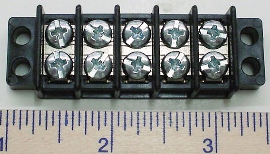
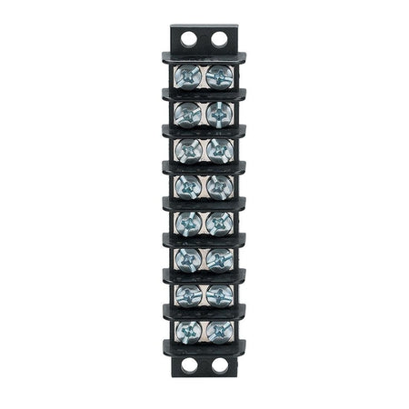
Terminal strips and barrier strips are kind of the same thing. The old style required crimp on terminals added to the end of the wire which connected to the screws. The euro style strips takes the wire in directly so the crimp on connectors are not needed. The terminals are connected across from each other. So if you had an 8 position strip,you would have 16 screws. Each screw would connect to the terminal across. You could jump adjacent terminals on one side for gang connections. Pre made jumpers are also available.
Grounding bars are used in home electrical panels to route all the wires inserted to common. They can also be connected to the metal box service panel itself. I use them on my layout. You can get these as bus bar extensions at home centers,there are different brands but it don't matter what kind,whatever is cheapest.
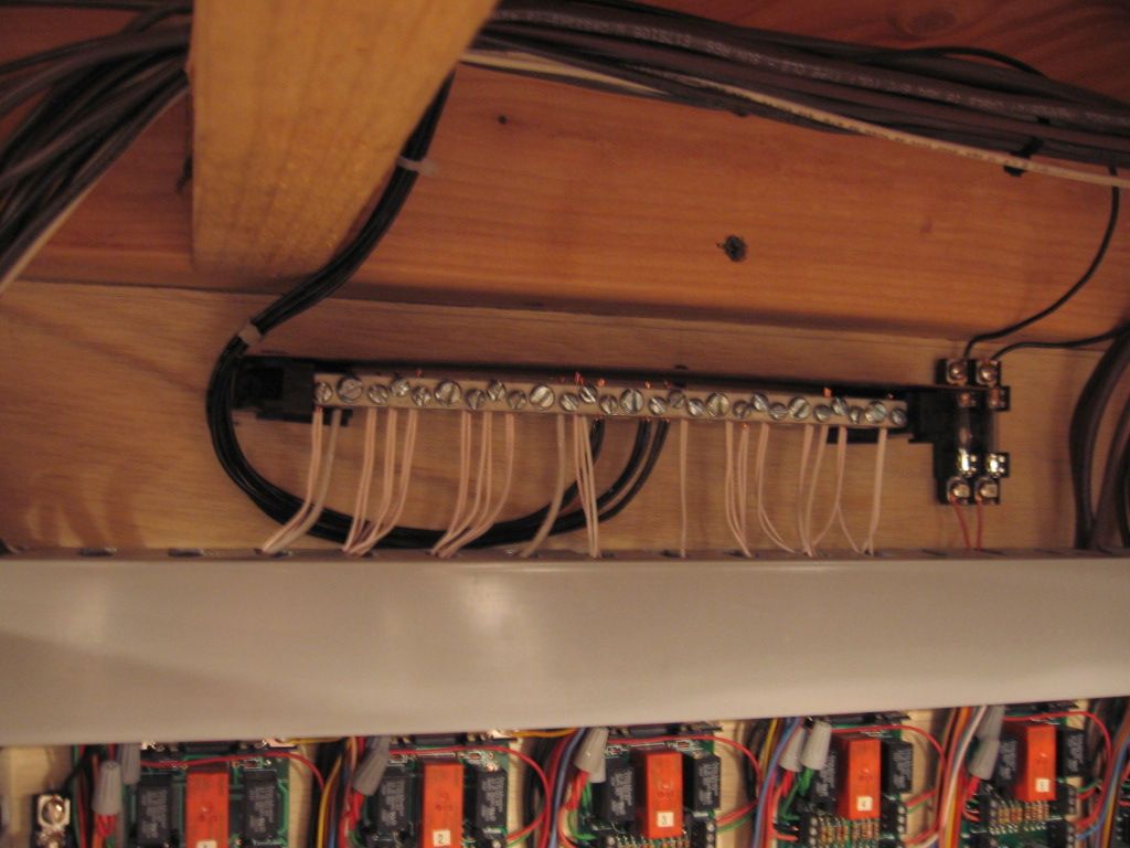
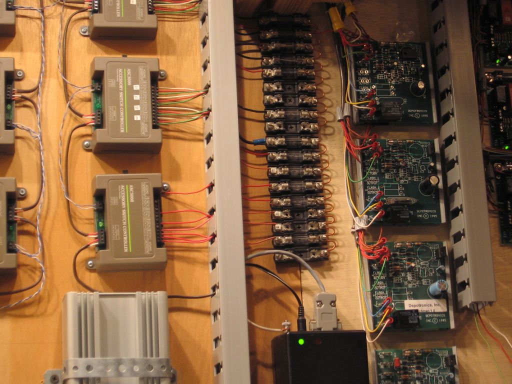
If you wade through this post,it shows some uses of both euro style and grounding bars. The layout has a shared common with all circuits,connected by grounding bars
Dale H
Where the term gets "loosely" used is when one refers to a bus type bar using these terms.
A bus type terminal strip provides multiple outputs from one input. the grounding bar in an expensive way to create a "bus terminal strip", well half of one.
Terminal strips and barrier strips are kind of the same thing. The old style required crimp on terminals added to the end of the wire which connected to the screws. The euro style strips takes the wire in directly so the crimp on connectors are not needed. The terminals are connected across from each other. So if you had an 8 position strip,you would have 16 screws. Each screw would connect to the terminal across. You could jump adjacent terminals on one side for gang connections. Pre made jumpers are also available.
Grounding bars are used in home electrical panels to route all the wires inserted to common. They can also be connected to the metal box service panel itself. I use them on my layout. You can get these as bus bar extensions at home centers,there are different brands but it don't matter what kind,whatever is cheapest.
If you wade through this post,it shows some uses of both euro style and grounding bars. The layout has a shared common with all circuits,connected by grounding bars
Dale H
Thanks Dale. Very helpful!
Ground bus bar

Barrier Strip
Where the term gets "loosely" used is when one refers to a bus type bar using these terms.
A bus type terminal strip provides multiple outputs from one input. the grounding bar in an expensive way to create a "bus terminal strip", well half of one.
Thanks Carl. Do you have a less expensive alternative to using the grounding bar? I presume that would be the bus type terminal strip. Thanks again!
The grounding bar is one of the least expensive methods when compared to buying jumpers for the terminal strips.
However, I use these 12 point terminal bus bars for transformer power distribution.
You might also add a neutral bar. Note that it is similar to the grounding bar pictured but has insulated legs/stand-offs from the metal electrical panel enclosure.
Note the black plastic ends.
Note the white plastic ends.

Ground bus bar
Barrier Strip
Tom,
Very, very helpful! Are the two holes at the ends of the Ground bus bar used to screw/attach age bus bar to the table, etc., and, do you just run the ground wire from the transformer under one of the screws, likely on the end?
Thanks again!
The grounding bar is one of the least expensive methods when compared to buying jumpers for the terminal strips.
However, I use these 12 point terminal bus bars for transformer power distribution.
Thanks Carl! The link was very helpful, and I bought several of the 12 point terminal bus bars.
You might also add a neutral bar. Note that it is similar to the grounding bar pictured but has insulated legs/stand-offs from the metal electrical panel enclosure.
Note the black plastic ends.
Note the white plastic ends.
Thanks, Mike. What do you use the neutral bar for?
In the model train world I use the neutral bars for all commons, both accessory and track common. You would use the ground bars for the same. The plastic ends would allow for insulation from the mounting surface, which in most cases would be wood, not really a problem.
In an electrical panel many times the neutral wires and ground wires are separated, i.e. the insulated black or white plastic ends are the separation, while the ground bars are attached to the metal panel enclosure with the two self-tapping screws show.

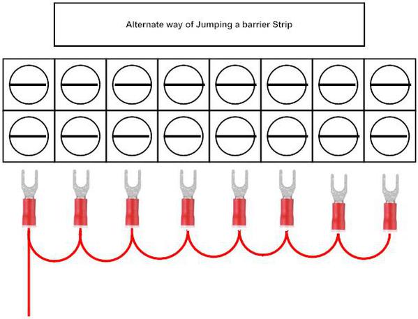
this is the old school way of using terminal barrier strips using jumper strips

this is an alternative to the jumper strips
as you can see each set of terminals opposite each other are connected so to use you connect a single power line to the input side and multiple outlets going to your light buildings accessories or what ever
you can also split the barrier strip so that half is hot and the other half is ground on the same strip
hope this helps


Thanks for all of the help, and for the excellent photos! The wiring is going well: no barriers so far!
Cordially,
Dennis
your welcome i am glad that i could help
Not that the barrier strip isn't useful, or that suggesting the use of them is somehow wrong.....but. I was probably making my second or third one of these when I realized what a total waste of time and money they are.
I believe I'll bypass the whole mess when wiring the new layout by using those neutral bars shown earlier. It's not like we're transmitting 120 volts through them. The savings in connectors alone, not to mention barrier bars, would pay for each neutral bar.
Bruce
to each his own i like the strips due to the fact that i dont like to run even 20 volts through an aluminum strip that conducts unless it is a ground which those are for.
we are adapting Electrical components to our model railroads to use as we see fit to use however if something were to happen to the layout and a fire was caused the investigation would show what was used and could possibly be the culprit and insurance may not cover the damages
this is why i do the best that I can and limit the openness of the possibility of problems
I'm back at wiring again, and the excellent posts that Forum members made above have been a much needed and helpful refresher. Given the passage of time, I'm really glad that I reviewed this again.
The barrier strips allow for flexibility that the "neutral bars" don't allow for. I use barrier strips all the time for various uses. When used for accessory power I usually don't run the same voltage thru all of the connectors. I might run 14V to 4 of them and 8V to the rest. you just don't connect all of them to each other. In this example I connect 4 together for the 14V and tie the others together for the 8V.
Of course one does not need to do that for the ground/return wires.
- walt
walt rapp posted:The barrier strips allow for flexibility that the "neutral bars" don't allow for. I use barrier strips all the time for various uses. When used for accessory power I usually don't run the same voltage thru all of the connectors. I might run 14V to 4 of them and 8V to the rest. you just don't connect all of them to each other. In this example I connect 4 together for the 14V and tie the others together for the 8V.
Of course one does not need to do that for the ground/return wires.
- walt
Walt,
Great idea. Do use use different transformer binding posts through the 14v and 8v connectors, or do you vary the voltage to the accessories manually through the same transformer binding post depending on which accessory you are actually using at that time?
Dennis, I have a 'V' that I use for accessories. It has 4 throttles. Over time I have recorded what voltage works best for each accessory. Now knowing that I can group them into 4 divisions which is plenty. I set the throttle on the trannie and put a "do not touch" sign on it. Mostly it's just lights that I'm controlling but even there I find different voltages important. For instance, I have 40 to 50 of those Lionel street lights and many stand-alone lights that I use in structures. Being able to vary the brightness helps. You get the idea.
Since I only have a Christmas Layout, knowing how to group them each year helps make it an easier setup.
- walt
Dale, I've been looking for, but never have seen, jumper strips for the euro-style bars. Where have you seen them?
You can fabricate terminal strip jumpers. Solid #14 ga wire.
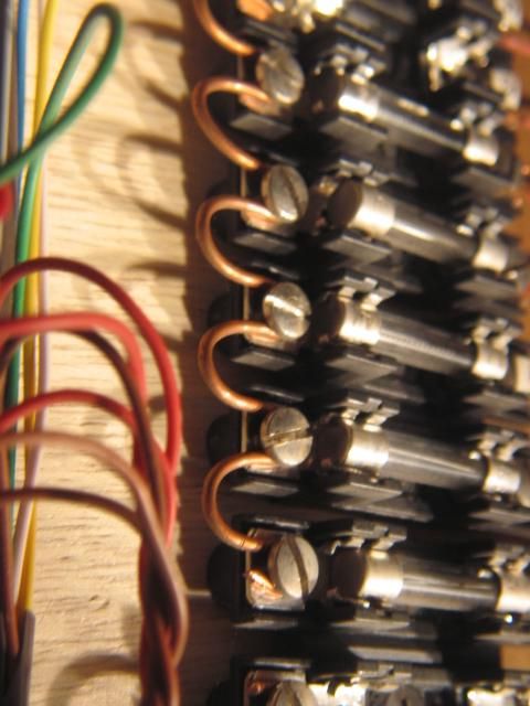
Mike CT posted:You can fabricate terminal strip jumpers. Solid #14 ga wire.
Now, THAT is clever and very neat.
Thanks, Eddie
When you can find them, Radio shack would sell barrier strips with jumpers.

These generally made these pretty easy. I have also used grounding bars/neutral bars for the same purpose. Given the low voltage I just screwed them into a scrap of 2" x 4", then mounted the block out sight.
Just to add that for a limited number of connections, the 5 position Wago connector is handy - all 5 positions are connected to each other. Wago connectors work with stranded or solid wire, supports 12ga down to 28ga, and UL listed and rated for 600v and 20amps. There is also small openings on the back (not shown) that allows use to use meter leads to probe.
I use 3 position and 5 position as I am putting my layout together.
Wago 222-415 shown below. Three position is 222-415


MED posted:Just to add that for a limited number of connections, the 5 position Wago connector is handy - all 5 positions are connected to each other. Wago connectors work with stranded or solid wire, supports 12ga down to 28ga, and UL listed and rated for 600v and 20amps. There is also small openings on the back (not shown) that allows use to use meter leads to probe.
I use 3 position and 5 position as I am putting my layout together.
Wago 222-415 shown below. Three position is 222-415
Ok, thats really interesting. I can get a bag of 100 of the 3 position (222-413) for about 29 cents each.
Also, it appears that its internally rated at 32 amps. 12 gauge wire is only rated at 20 amps, which is why they should only list it at 20amps, but its nice to know that the internal connectors are actually rated much higher.
eddiem posted:
Thanks Eddie for showing that!!! I have about 10 of the European style and this device will really help me wire them. This forum always has helpful info and this is certainly one of those!
- walt
I use the barrier strips with dual screws. I purchase them in 28 terminal length and cut them to suit my need. My only solder connections are feeders to the track. I connect crimp lugs to the strips. The allows easy modifications, troubleshooting and repairs. The screws don't loosen either.
walt rapp posted:Dennis, I have a 'V' that I use for accessories. It has 4 throttles. Over time I have recorded what voltage works best for each accessory. Now knowing that I can group them into 4 divisions which is plenty. I set the throttle on the trannie and put a "do not touch" sign on it. Mostly it's just lights that I'm controlling but even there I find different voltages important. For instance, I have 40 to 50 of those Lionel street lights and many stand-alone lights that I use in structures. Being able to vary the brightness helps. You get the idea.
Since I only have a Christmas Layout, knowing how to group them each year helps make it an easier setup.
- walt
Thanks Walt,
Your comments will greatly assist with my current wiring project(s). By the way, what is a 'V'?
jhz563 posted:When you can find them, Radio shack would sell barrier strips with jumpers.
These generally made these pretty easy. I have also used grounding bars/neutral bars for the same purpose. Given the low voltage I just screwed them into a scrap of 2" x 4", then mounted the block out sight.
Amazon has a great selection of similar items. Here are the: "10pcs(5 Sets) 12 Positions Dual Row 600V 15A Screw Terminal Strip Blocks with Cover + 400V 15A 12 Positions Pre-Insulated Terminal Barrier Strip (Black/Red)..."Size:e)5 Set 12 Position 600V 15A Screw Terminal Strip, for $12.99 (If you search, "barrier strips with jumpers", you will find even more choices):


MED posted:Just to add that for a limited number of connections, the 5 position Wago connector is handy - all 5 positions are connected to each other. Wago connectors work with stranded or solid wire, supports 12ga down to 28ga, and UL listed and rated for 600v and 20amps. There is also small openings on the back (not shown) that allows use to use meter leads to probe.
I use 3 position and 5 position as I am putting my layout together.
Wago 222-415 shown below. Three position is 222-415
Thanks MED, great suggestion. Here's the description for that item from Amazon, which can easily be ordered in different amounts from 10+:
"Wago 222-415 LEVER-NUTS 5 Conductor Compact Connectors 80 Pack"
10 of them are priced at $9.45. ( I haven't attempted to compare prices across suppliers, and am attempting to use this pricing as an example of availability and "ballpark" cost.)
John H posted:
Thanks John, I was going to search Lionel "V", but that's far more illustrative!!! I presumed he was referring to a vintage Lionel transformer that I wasn't familiar with. That helps, because I can just use my old ZW from my youth -- which I'm sure will be overkill!
FYI, On Amazon there is a 75-piece assortment of NON-Wago's for $19.99.
CORRECTION
MY SON POINTED OUT TO ME THAT THESE ARE NOT WAGO AND ARE NOT UL LISTED. So I would not use them in household wiring
I have one for the exact purpose discussed. 8 volts for drum loader, 14volts for Fastrack switches, 12 volts for milk car, etc.
John,
That's a really cool looking transformer!
Those ancient Lionels around WWII were excellent, so long as used with external breakers on all circuits. Do be aware that the internal breaker only cuts out the U post. Separate breakers on each output is not adequate protection.
Why are separate breakers on each output not adequate?
If the internal windings of a transformer can only take 10 amps, putting even a 5 amp fuse on each output would mean 20 amps are flowing through the windings. The internal breaker would open at a total of 10 amps, if working.
so long as used with external breakers on all circuits
Separate breakers on each output is not adequate protection
My apologies, but you lost me. How should it be protected?
Unlike the later made VW and ZW transformers, the early PW "V" and "Z" had a separate winding for each of the four outputs. The later VW and ZW shared common windings, so the failure of one affected all four. Also, the earlier "V" and "Z" were / are better for good source powering because, not being shared windings, and not sharing amperages, you have full amps from each post as listed, no drop due to having shared with other of the four output circuits. I have more than one of each, the "V", "Z" and VW as well as ZW..... prefer the earlier models for better sustained supply. IMO...….
Jesse TCA
On a more expensive note there are the "distribution Panels made by MTH. very similar to barrier strips with jumpers. One hot and one neutral input and I believe 24 out puts of each hot and neutral.
Jesse, take a look at the type V & Z manual, with schematic, available on the olsentoy website. They speak of it as having a 2 coils, one giving 6 volts, and the other 6-24 as tapped off. The schematic shows 4 rollers running across the single 6-24 volt secondary.
The breaker opens the feed to U. Thus, there is no protection against a short between any of the A,B,C,D terminals.
http://pictures.olsenstoy.com/cd/transfmr/psv1.pdf
A lengthy srticle indicates that there were many internal changes to the V over the years it was in production:
coach joe posted:On a more expensive note there are the "distribution Panels made by MTH. very similar to barrier strips with jumpers. One hot and one neutral input and I believe 24 out puts of each hot and neutral.
coach Joe,
Those "distribution Panels made by MTH" are great - very easy to wire. They do take up a lot of real estate though! I have moved to doing most of my wiring on the slightly recessed 1" x 4" frame members for my train tables. That way, I just pull the wires through the table, and do the wiring on the sides of the layout benchwork -- no more crawling under the tables. The MTH distribution panels are too large for the 1" x 4" framework.
I will just put removable skirts around the layout, covering the wiring, but, giving ready access from the sides.
On the subject of Wago connectors, for many years Ideal has had a line of similar connectors that do not have levers and are slightly smaller.
Mucking around on the internet, I came across a video in which a man makes up a length of what appears to be 12-gauge wire, with a series of splices---wago connector, crimp connector, wire nut, Euto-style screw connector---and then fed 70+ amps through it for awhile. Melted the insulation off the wire, and the Wago was the first connector to smoke.
Why would anyone care what happens to any connector at a 70 amp load? Household 14 awg wiring is good for 15 amps max, and our train wiring is usually less than that, even for track power. 😜
Rod
It is a measure of how good a contact a particular conductor makes.
RJR posted:On the subject of Wago connectors, for many years Ideal has had a line of similar connectors that do not have levers and are slightly smaller.
Mucking around on the internet, I came across a video in which a man makes up a length of what appears to be 12-gauge wire, with a series of splices---wago connector, crimp connector, wire nut, Euto-style screw connector---and then fed 70+ amps through it for awhile. Melted the insulation off the wire, and the Wago was the first connector to smoke.
Found that video and watched it. If the connector is still fine after the insulation has been charred off of the 12g wire, thats a good sign it can handle the job. Also, if the connection remained in tact after the 90amps of current burned the 12g wire in half, thats another good sign.
The way he conducted the test was a little silly (although cool) because the 12g wire was basically converted into a stove top heating element. So the wire itself was generating a tremendous amount of heat and was causing all of the plastic on the connectors to melt, and one couldnt be certain how much heat was being generated by the connector junctions themselves.
Agree, MJCAT.
Supplementing my comment above, some years ago I was in discussions with a manufacturer of marine air conditioning units. They advised me that the principal cause of problems was that crimp connectors would overheat & fail. I have encountered that issue on marine a/c units, usually when a unit has been operating continuously for several days at about 17 amps on a12-gauge circuit. On these units, I always replace crimped splices in a/c unit with an Ideal product that uses a metal ring with a set screw, over which a cap is screwed
Here is a small portion of the wiring that I have completed with the help of this thread. For this location, I will next connect the yellow accessory wire to a bus bar. Once the wiring is completed, I plan to cover this wiring with a skirt or easily removable facia board :

It looks great but you missed securing the green wire loom Dennis.
Also, to move stresses off connections of heavy, draped wire, push the bundle to the left thru the wire stay slightly and wrap the wire bundle with a small zip tie(s) tightly to the left of the wire stay so it's head will butt against the wire stay when released.
Ideally the wires should sort of push at the terminals vs pull. Any wire stress down the line to the right is now held at the wire stay vs the crimp connections. Loops of excess I hang on the run (the right).
A fun way to dress some minor excess slack is to wrap a few turns around a phillps screwdriver or pen to "shorten it" then pull to length, then pull the coils off the driver, and slowly pull it to length.
It's silly, but visually effective dress.
Thanks Adriatic! All very good suggestions.
Adriatic posted:
Hi Adriatic,
I enjoyed and appreciate both of your posts, and now have some time to implement your suggestions. In this regard, your pen/Philips screwdriver suggestion made me smile! I used the red/burgundy colored Lionel solid wire for my Super "O" layout as a young boy, and frequently used a pencil to coil some wire to give me "wiggle room" if I later made a modest change to the location of an accessory. (I still have a few lengths of that 1960's era "coiled" wire in my miscellaneous wire box!)
I still use this method occasionally under the table if I envision possibly moving something a short distance in the future. That's a wonderful layout "Tip & Trick" that I should probably use occasionally on the 1"4" layout framing where I am now running most of my wiring, as you suggest.
Question: Should I just plan in the future to place the plastic "wire stays" slightly above each connection with the barrier strip where possible? I generally have room on the 1" x 4" layout framing for this.
Finally, those wire "looms" were installed when I first started the wiring and I can probably eliminate them and use the pencil/pen tip and trick to replace the larger coils with a short 1" coil of wire. In this regard, each of those white, red and green colored wires are for a mainline track connection, so I likely wanted some flexibility when I started my layout wiring back when I made the O.P.
Thanks again!
Looms that are exposed get pulled on or bumped sooner or later, so yes. Would they survive without it? Maybe.
Ideally you dont want stress on the connection themselves, especially weight putting reversing torque on the screw heads. The vibrations will do their best to loosen a screw or two then. A crimp can't pull out if the stresses of an accidental yank are consentrated at a wire stay.
Look at how heavy outdoor ac lines get terminated. A guy line comes from high off the pole and has a cable stay to hold the main weight of the long line off of any electrical connections. Looped slack being on the runs side gives it a beter chance to slack out under extreme pressures (tie loops ONCE just enough to hold loops reasonably, two will hang up uncoiling), less chance of wire damage, you just have to re-coil/re-tie.
It's silly but the "real pigtail"(?) does garner smiles from folks that would never look twice at electrical too.
We'd be assessed by non-techs for general order, cleanliness, etc.. This touch was a secret weapon to draw a bored eye away from something minor missed (usually by assistants) ....surprise visit protection ![]()
Adriatic posted:
"Ideally you dont want stress on the connection themselves, especially weight putting reversing torque on the screw heads. The vibrations will do their best to loosen a screw or two then. A crimp can't pull out if the stresses of an accidental yank are concentrated at a wire stay."
That's helpful, and will be useful information for many different circumstances including this specific one. It also makes very logical sense after better understanding the issue, and thinking about the various forces at play over time.
 I'm continuing with my layout wiring and Murphy's law has been added to the electrical equation. As it turns out, the wire in the previously posted photo (above) that I did not cut longer than needed is the yellow accessory wire! I have now run that wire to a bus bar, and can proceed with wiring the lighted accessories that are destined for that particular portion of the benchwork.
I was also able to utilize the helpful pointers for the actual wiring that Adriatic posted above.
Would using the left side of the left hand terminal strip work at all or for a while? .
Remove any jumper you need to by clipping the strip that connects each terminal section. Let the wire color and maybe some term.-screw spaces keep you organized. Using a T-strip doesn't have "rule" forbidding running hots and com.s both, or unrelated circuits. Closest you see is hot and ground constants tend to be run on the ends; switched/ control/ etc. in between.
If using that strip leaves the wire in the hole shy of the strip, splice that on the underside or replace it and save that long scrap for dividing among other short runs to come, hopefully related, etc..
Long run savings?.... if you cut T-strip jumpers with thoughts of how you might use scraps long term. Avoid clipping a single one off because thats definitely waste; a pair or more just might get used one day. Any single slice reduces the effective total jump count by 1 when reused together so be careful with cut count vs terminal counts, especially if you attempt any convoluted math to plan ahead. High count scrap drawer stock makes for easier math imo ![]()
Kinda like extra brick overstock buffer % applied to a job estimate so you don't run shy. Sometimes that excess can be forwarded to a new job, sometimes not. (if builder own it vs the build-ee, etc) I didn't use brick much outside of architectural drafting and some trades estimating, blueprinting, surveyor mapping type work. I.e. a lot of paper brick and spiral bound mortar, not too much in crusty knuckles and grey boots that didn't involved a pour....
( Detroit-y trades & elders fav. story semi-re-enacted : ) .... Mostly knocking holes in brick, then sealing lots of hvac/plumbing around the GM headquarters, south side apts, foods, business, etc.. I'm brain farting on the traditional old school "area" and buisness name; But one apt house, was actually once a trade school my mom's dad had taught welding at in the 30s-40s.
To save a few class rooms of people, he was forced to catch, wrestle, and push a large acetylene tank who's valve broke off in a tip over, right out of a 4th floor window into that 1st former alley off the water, south of GM where it became a northbound rocket. Nobody got hurt though Grandfather always said he was very tempted to bury his foot "somewhere" in the idiot who didn't drape the tipping safety after it was stood in place but settled for suggesting he drop the class before temptation won.
Over half a century later, knowing the story and location, I got to drop bricks and other heavy debris from the same window (after I moved the dumpster over a room with my truck. ![]() ) and recall thinking about how quick it was all processed by him; the counting of lives vs risks going out the window to below and those negligence risks; manslaughter vs just running as they had time, vs being unable to warn other floors, vs was he able to even catch or control it (he WAS a very large man overall, +300lbs easy in shape. A near Shaq sized, broad, tall, Englishman; my hand spread, fits easily into both mens palms in a high five {high for me anyhow
) and recall thinking about how quick it was all processed by him; the counting of lives vs risks going out the window to below and those negligence risks; manslaughter vs just running as they had time, vs being unable to warn other floors, vs was he able to even catch or control it (he WAS a very large man overall, +300lbs easy in shape. A near Shaq sized, broad, tall, Englishman; my hand spread, fits easily into both mens palms in a high five {high for me anyhow ![]() } )
} )
Anyhow, I think that's it for a chance at an interesting Mason's story that isnt Masonic ![]()
Adriatic, since the middle of the last century I have been saving items I might need some day. Please have pity on my Executor, who will face the piles of items.
Adriatic posted:Would using the left side of the left hand terminal strip work at all or for a while? .
Answer: Good suggestion! I actually have a number of lights, and lighted accessories to wire on the table, and those remaining "black" terminal spots are for the ground wires.
Using a T-strip doesn't have "rule" forbidding running hots and com.s both, or unrelated circuits.
Answer: I likely should know the answer, but what is a "T-strip"?
Anyhow, I think that's it for a chance at an interesting Mason's story that isnt Masonic
Answer: That was an interesting story!
Back of my control panel.
Upper row, Accessory power connections, and uncouple magnets. Bottom left, connections to the O-22 switches. Bottom right, UCS tracks

Front of Control Panel Track Power.

Steve
Connections for my 97 Coal Elevator on underside of layout.

Steve
FWIW, you only need to have 3 wires going to a #97. Note under the elevator that a bar connects 2 terminals. Neither of these needs to be used. On the side with 2 terminals, connect the terminal not on the bar to ground. Feed hot directly to your controller, and connect the two output wires to the two terminals on the 3-terminal side that are not connected to the bar. Thisa cuts voltage loss.
Similarly on 022 switches, leave off the wire from the switch middle terminal to the controller, and feed the controller directly from transformer ground. Switches get hot from the track or preferably the fixed voltage plug.
RJR posted:FWIW, you only need to have 3 wires going to a #97. Note under the elevator that a bar connects 2 terminals. Neither of these needs to be used. On the side with 2 terminals, connect the terminal not on the bar to ground. Feed hot directly to your controller, and connect the two output wires to the two terminals on the 3-terminal side that are not connected to the bar. Thisa cuts voltage loss.
Similarly on 022 switches, leave off the wire from the switch middle terminal to the controller, and feed the controller directly from transformer ground. Switches get hot from the track or preferably the fixed voltage plug.
I did not have the original controller for my 97. I re-configured a controller for a UCS Track. The right button opens the solenoid coil to unload the 97. The left button operates the bucket conveyor. The doorbell button operates the control rails to unload the dump car.

I custom built my control rails to dump into the unloading tray for the 97. I placed an un-couple magnet before the control rails so I can drop off the dump car in position to un-load into the tray.

As to my O-22 switches, I use 2 wire 18 gauge speaker wire. Run a 2 wire pair to each switch. The switch controllers on the control panel are grounded to the terminal strips on the back of my control panel. A separate wire is run from accessory power to the voltage plug on the switch machine.
Below you can see my connections at one of my O-22 switches. Built platform boxes to hide the switch machines.

Steve
Here is what I did on the underside of the 97. I did not use the binding posts on the top of the 97. I added a couple 2 post barrier strips. Replaced some of the old original wires that were brittle and frayed.

Steve
Excellent solution to use the barrier strips! A great work-around.
I've resumed my wiring efforts, so, I thought a quick "refresher" would be in order.
Access to this requires an OGR Forum Supporting Membership


