
Clip
These are standard 72x30 inch plastic folding tables. I have built onto them some extensions that make them 90 inches long. So far I have finished two of them. I also plan to build some 30x30 fitter sections. The idea behind making them 90 inches long is that it makes the tables somewhat compatible with the LCCA modular standards of 45x30 inches.

Attachments

Images (2)
  • Clip
  • Clip
Last edited by Flash
Original Post

Replies sorted oldest to newest

Flash,


Looks good.  Just wondering, the tables are 30" wide so the modules are 31.5" wide.  They won't match with the LCCA modules.    Any way to mount the side strips on the top edge instead of the side of the table?


My modular design uses 30x30 corners and 30x60 straights.

I posted this a while back on the LCCA thread:


it


The important part is track spacing... 3.5" from the edge on the outside track and 6" between track center rails.


Ed

Correct, the important part is track spacing.

The other important part is table height.

By themselves the tables are like 29.5 inches wide. With the extensions they come out at about 31 inches wide.

A little bit of extra width (or even narrower width) will not prevent modules from being butted up against each other and clamped or screwed together.

Keep us updated.


My modules have no legs.  I bring a few folding tables to sit them on.  In my case, I don't plan on connecting them to anything but my other modules for our club train shows, visits to schools, nursing homes, etc.


I used one sheet of plywood to make lots of strong 2.5" strips for the edges.


What will you use to transport these?  My limiting length factor was my SUV so I figured 60" would fit in almost anything.


Ed

Originally Posted by eddiem:


What will you use to transport these?  My limiting length factor was my SUV so I figured 60" would fit in almost anything.


Ed

They still fold up. So, folded up, they are 45x30 inches.

Yes, all the track has to be taken off before folding them up. No big deal, its Fastrack.

Special Modular Layout Design:


I am building a layout to be set up on one side of a two car garage.  It will be designed as individual modules but they not intended to be compatible with or attached to train show setups or similar. My intent is to make everything "plug and play" so the layout can be easily set up and taken down or modified (enlarged) if necessary.


All wiring of the control system will also be designed as modules so that custom cables will be run between all control system modules and the layout.


The module height will be 48 inches above the floor. The modules will be supported by specially designed 2x4 legs attached with bolts, washers and wingnuts. The track will be laid on a special raised roadbed so that all track and signalling wiring will be self-contained (and hidden) within the roadbed structure. Wiring between modules will be via special connectors.


Note: The largest component of the layout will be the "WYE" section which is 72 inches by 36 inches.  This means that I can easily transport the layout sections in my SUV if necessary.


The main focal point of the layout will be a WYE entrance to a center stub yard for use with passenger trains or intermodal freight. The outer loop will use O-72 track with O-72 turnouts throughout.  An inner passing siding will use O-54 track.


Last edited by pro hobby

As they sit, my tables are about 30 inches high. I do need to raise them up.

I figure I can do do this on of two ways.

1. build stands out of wood for each table leg to stand on.

or

2. find metal pipe of appropriate diameter that can be sleeved over the table legs.


I like the idea of the pipe sleeves but I'm not sure how stable they would be and if they would make the already noisy fastrack on hollow table even noisier.

I had to modify similar folding tables to increase the height.

My method was to remove the plastic caps from the table legs and insert the needed lengths of 1/2 inch diameter metal electrical conduit to acheive the desired height.

The ends of the conduit were then inserted into 30" lengths of 2 X 4 that had 1/2 inch diameter holes drilled partway in them to accept the conduit pieces.

Drywall screws drilled through the edge of the 2 X 4 into the conduit completed the assembly.

When the tables were to be closed up the U-shaped wood/conduit assemblies were easily removed from the table legs.

Hope that helps.

Wiring? Thats a very good question... hmmm...


I plan to have to have the wires to the tracks just on top of the tables. The track will have to be removed every time the tables are folded up and fishing wires through the tables would be a pain.

Bus wires will be run along the outside edge of the tables with terminal blocks in appropriate places.

I plan to operate all switches manually so I wont have to deal with messy switch control wiring.


As I progress I'm sure I will figure out better and neater ways to run wiring.

BTW, I think I should add that what I am building is a kinda Free-Mo concept for operating a 3-rail layout. Little to no scenery. Just track laid on tables that can be arranged in any variety of ways.

I know it all seems cheap and cheesy now, but hopefully I will be able to stick to it and make improvements over time.

Probably the first change I will make is removing the green outdoor carpet and replacing with grass mats. Then maybe add structures or scenes that can be placed anywhere.

Currently my plan calls for lots of track for operating multiple trains with little room for anything else.

But who knows what the future may hold.

Originally Posted by Flash:

As they sit, my tables are about 30 inches high. I do need to raise them up.

I figure I can do do this on of two ways.

1. build stands out of wood for each table leg to stand on.

or

2. find metal pipe of appropriate diameter that can be sleeved over the table legs.


I like the idea of the pipe sleeves but I'm not sure how stable they would be and if they would make the already noisy fastrack on hollow table even noisier.

The legs don't have to be real stable. Use an inexpensive version of quick clamps to lock the modules together. That adds stability.

Remove one of the rubber feet and get the i.d. of the leg. Then the o.d. The wiring conduit sounds like an inexpensive extension. See what will work, i.d. or o.d. size. You could drill a hole through both and use hitch pins or clevis pins to keep it in place.


Just tossing some ideas out.

Originally Posted by Flash:
Originally Posted by eddiem:


What will you use to transport these?  My limiting length factor was my SUV so I figured 60" would fit in almost anything.


Ed

They still fold up. So, folded up, they are 45x30 inches.

Yes, all the track has to be taken off before folding them up. No big deal, its Fastrack.

Well, not all of the track as to come off. Use a 5" straight at the joints, with a 2 1/2" set back on each module like the LCCA. Then a 30" and a 10" should get you to the fold joint. When up a 5" over the fold joint, then another 30" and 10" with a 5" to span to the next module. That would let you screw down everything but the 5" joiner pieces. Your table length is 2 LCCA modules long. (45") So, that should work. The width of 30" is the LCCA size. You could make a template for track orientation once you get the width spacing determined.

Originally Posted by Flash:

Wiring? Thats a very good question... hmmm...


I plan to have to have the wires to the tracks just on top of the tables. The track will have to be removed every time the tables are folded up and fishing wires through the tables would be a pain.

Bus wires will be run along the outside edge of the tables with terminal blocks in appropriate places.

I plan to operate all switches manually so I wont have to deal with messy switch control wiring.


As I progress I'm sure I will figure out better and neater ways to run wiring.


If you screw the track down and use the 5" joiners, then you attach the buss to the under side like the LCCA. The EastPenn guys have posted their plans using nice connectors. There's a couple of solutions to the connector issue.


It doesn't seem cheap and cheesy. It's a creative solution that will look good when assembled. I kind of like the grass carpet. It appeared to have rubber backing which will help a lot with sound abatement.

The large corners will be a pain 084 & 072. You would need 2 52" square tables.


The small radius corners 048 & 036 will work on a table standard length with fitters at the edge and the fold. You would need to cut a 10" for a fitter at the fold.


Here's a SCARM of a 72" wide table as an end piece.


Small Corner


That will give you 6' x ?' oval using the same table. A similar 36" table could be used to make a half corner, but I figured that you had already sourced the size table that you have now. 

The large corner is attached, but I couldn't fit it on a 30" x 72" table.

Attachments

Images (2)
  • Small Corner
  • Large corners
Last edited by Moonman

Flash,


Looking good! Lots of progress.  I'm working on my "portable modular"... adding a few more lengths.


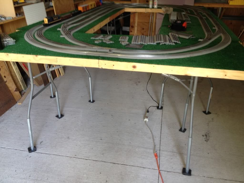
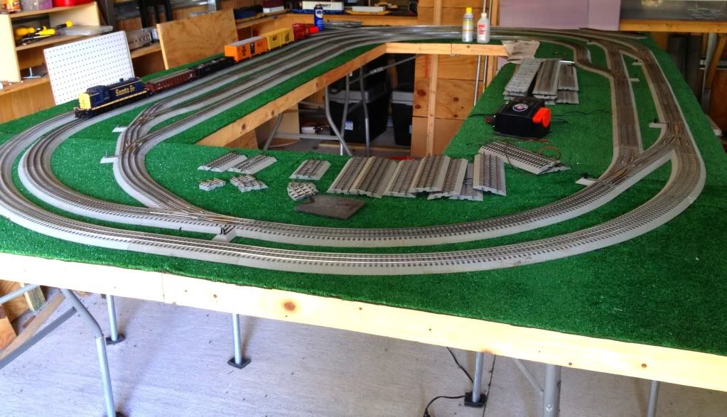
I DO LIKE the "flexibility" of unattached track!


I decided to make the 4 curves (30" x 30") and the O48 and O36 Fastrack with 5" joiners works perfectly.  Two corners together make a 60" long table for a 180 degree curve.  If you are doing 72", an additional (2) 5" pieces would work well if you decide to  put the track in a fixed position on the corners.


An advantage of doing fixed (nailed down) corners is that you can do all power feeds on the corners.  Easy to do and enough drops to carry power across the straights from corner to corner.  All of my track is fixed, except for the joiners and even though I put connectors on each module, the 4 corners work great.  Actually 2 corners work fine!


Keep us updated.  I posted a pic of the two modules I'm working on now.  They will give me a 5' x 15', 10' x 10' or 5' by 25' one sided viewing setup.  Lots of fun to think through the combinations and options.


For scenery, like buildings, I put a lamp socket on the table instead of trying to wire the building lights.  Works well.


Ed


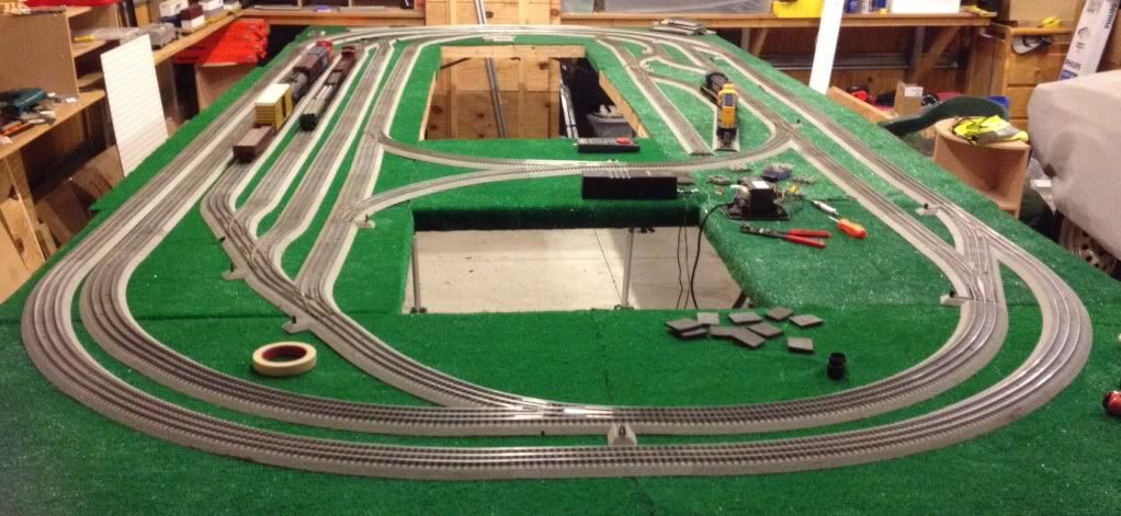
ps. heres a pic of the layout in the 5' x 15' mode (still have to make the (2) 24" x 30" filler tops.  Those will just support track - no wires or track attached.


double loop

Attachments

Images (1)
  • double loop
Last edited by eddiem

The oval setup above is four 90x30 inch tables arranged to make a 150x90 inch oval. Phase two will include adding some 30x30 inch modules to expand the oval. 


I sleeved the table legs with 1" conduit. Without the sleeves the tables are at 30" height. Now they sit at about 41" high. The higher tables makes it easier to work on but my 6 yo daughter says they are now too high. I guess I will have to build her a platform to stand on .

The higher tables also allow me to slide my riding lawnmower underneath which was a very important requirement for me.


The sleeves are easily removed so the table can be folded up and stored/transported when necessary.

Last edited by Flash

Flash,


I like what you have done and especially the track layout.


Do you use RR-Track or any way to get the track plan you used, as I am thinking what you did would work well in my basement layout. (That I have been procrastinating about and design, re-designing for over a year now.)


Thanks in advance,


Originally Posted by PRR2818:

Flash,


I like what you have done and especially the track layout.


Do you use RR-Track or any way to get the track plan you used, as I am thinking what you did would work well in my basement layout. (That I have been procrastinating about and design, re-designing for over a year now.)


Thanks in advance,


I used SCARM for track planning.

It was actually getting pretty frustrating using the computer to come up with a track plan. Making some of the curves and small fitter pieces work was not making me happy but it did help me come up with a plan.

My frustrations with the software are what motivated me to get these tables up and working. Its a lot easier (for me) to have physical tables to work on and then use trial and error for fitting in the small sections and curves.


The outer loops are o72 and o60. The inner sidings are a blend of o36 and o48.

I try limit o36 curves as much as possible but I have to use o36 switches in the yard area because its all I have.

Looks good. I'd like to see the other end, the top right corner in the posted photo. It looks interesting.


You can sacrifice 5" and 10" straights to make custom fitters to avoid the little guys. See the end of the LCCA FasTrack modular specifications. The first one or two result in an ok job, then you can make really nice ones.


It looks like your straight off of the wye is forced a little. Take out the offender so the track is relaxed and measure the size you need roadbed end to roadbed end in the space.


Would you mind sending me your SCARM file?

Flash,


Looks real good!  You have a layout design but by not laying the track permanently, it's changeable.


I'm working on two more pieces to my modular and do attach the track to the baseboards.  It's more for traveling than a home layout so it's easier to have the track and wires in place.


I need to get the last two pieces done.  Our club has a few visits to assisted living homes scheduled for Nov and Dec!  Looking forward to a real test of how it all works together.


I don't know what your plans are for buildings, etc. but I decided to use lamp sockets and bulbs on the baseboard instead of the lighting built into the buildings.  Easier to move, wire, and setup.


Ed


my church uses pvc pipe to adjust the height of tables such as this.
Originally Posted by Flash:

As they sit, my tables are about 30 inches high. I do need to raise them up.

I figure I can do do this on of two ways.

1. build stands out of wood for each table leg to stand on.

or

2. find metal pipe of appropriate diameter that can be sleeved over the table legs.


I like the idea of the pipe sleeves but I'm not sure how stable they would be and if they would make the already noisy fastrack on hollow table even noisier.


Originally Posted by Moonman:

Looks good. I'd like to see the other end, the top right corner in the posted photo. It looks interesting.


Back right corner.

Too many S curves. Did the best I can with what I have. Maybe later I can straighten them out a little.


Back left corner.

Too much o36 here. But I wanted more yard space so I will have to deal with it.


I added a 1 3/8 section to this leg of wye. I think it was a little too much but we will see how it works.


Here are some of my custom cut sections in the straight leg of the wye. Not perfect but they work.


It looks good. I see you had the same issue I had running 2 Track main(072/060) . In hind site I would of used 084 for outside track and 072 with 084 to transition out of the curve on the inside track. Currently now down to one track main. My 072 Y switches were modified by removing the 1 inch block and removing the ballast section that was left so I could use 072 half curve and still had 2 inch separation for the sidings in the yard. Is it raining by you?


Doug

Post
The Track Planning and Layout Design Forum is sponsored by

AN OGR FORUM CHARTER SPONSOR

OGR Publishing, Inc., 1310 Eastside Centre Ct, Suite 6, Mountain Home, AR 72653
800-980-OGRR (6477)
www.ogaugerr.com

×
×
×
×
Link copied to your clipboard.
×
×