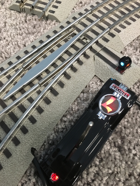
09134714-F4EC-439B-A9A5-65A95F9DA564DDB44240-D080-49FB-AEA1-BE597458C27Awell this is a 048 switch that is new. Installed the switch on the temp loop and programmed it. The controller is Red being thru and when you look at the switch itself, it is backwards.  It wants to derail everytime something goes through.  Anyone have an idea.  I have looked for the color codes for wiring and it is wired correctly as far as the diagram that comes with the pamphlet for the controller. 

Thanks 

Attachments

Images (2)
  • 09134714-F4EC-439B-A9A5-65A95F9DA564
  • DDB44240-D080-49FB-AEA1-BE597458C27A
Videos (1)
96FBFAFC-6210-48AB-A6C8-AFD91487DC61
Last edited by Southern4501
Original Post

Replies sorted oldest to newest

Your video is a little too close to see the route.  Assuming that the lantern is correctly showing red for the diverging route but the controller is green, try reversing the red and green connections at the switch.  It is possible (likely) that the wires inside the controller are connected wrong.  You can open the controller and reconnect the wires correctly.

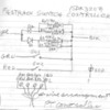
There's only one wire, the yellow one, that causes the controller to go green or red. The voltage on the yellow is +5 vdc for green and -5 vdc for red. It seems that something is mis-wired inside the switch in regard to the output on the yellow wire. But...what if the yellow and black are switched...hmmm...that would do it. Seems like that would interfere with the throw of the controller, but check that out anyway. Here is a picture of the proper arrangement of the wires.FT Switch Controller

Attachments

Images (1)
  • FT Switch Controller
Danr posted:

Your video is a little too close to see the route.  Assuming that the lantern is correctly showing red for the diverging route but the controller is green, try reversing the red and green connections at the switch.  It is possible (likely) that the wires inside the controller are connected wrong.  You can open the controller and reconnect the wires correctly.

When i press the aux1 the switch goes to diverge and when i push aux2 it goes to thru which is backwards.  I did rewire the  controller red and green wires to fix the control part but the switch is still the same. Backwards. 

Southern4501 posted:
Danr posted:

Your video is a little too close to see the route.  Assuming that the lantern is correctly showing red for the diverging route but the controller is green, try reversing the red and green connections at the switch.  It is possible (likely) that the wires inside the controller are connected wrong.  You can open the controller and reconnect the wires correctly.

When i press the aux1 the switch goes to diverge and when i push aux2 it goes to thru which is backwards.  I did rewire the  controller red and green wires to fix the control part but the switch is still the same. Backwards. 

The switch lantern is correct in your photos. The indicator points down the track so the 1:48 engineer can see the postion.

cjack posted:

Perhaps you can compare the internal wiring to another switch?

Well thats what i thought about doing. I was wanting to hear some thoughts before opening up a working one. At first glance the bad switch controller only has 2 screws in it. Wires are ok.  Then i opened up the switch itself. Everything looks correct. So i looked at the motor and it is wired correctly, but it is turned 180 out from the working switch. Red which is inside motor is to the outside of the bracket and yellow which is soldered to the outside casing is to the inside of the bracket.  Reversed from the working switch.  I broke the dang solder connection which is tiny and dont have my solder iron at home. I will have to fix it at work and test it after work. 

Add Reply

Post

OGR Publishing, Inc., 1310 Eastside Centre Ct, Suite 6, Mountain Home, AR 72653
800-980-OGRR (6477)
www.ogaugerr.com

×
×
×
×
Link copied to your clipboard.
×
×