


Sorry about that I had it in there but not open to display. I got that fixed now thanks
When will these be available? I think I could use one.
Please put me down for 2 units.
Jay
I'm targeting probably about a month to six weeks for firm commitments. At that point, anyone that wants one will put down a deposit to cover the cost parts as I don't want a lot of expensive parts around that I don't use. The deposit will be on the order of $50. At that point, I'll make the final parts order for the quantity that I have deposits on. When they're assembled and tested, all the folks with deposits will be notified and make shipping arrangements. Right now, the final price looks to be $129 including the $20 donation for each unit going to the ACS in Dale's memory. That gets you everything you need to install it, the buffer, the 24V power brick, and the earth ground cable to tap off the earth ground from the TMCC/Legacy power cord.

Given the realities of ordering printed circuit boards in quantity, I'll probably have blank boards after the initial build, it doesn't really cost much more to order 100 vs 50, around $10. At that point, my plan is to make the design available for anyone to assemble that missed out on the initial build. Since I'll likely have blank boards, those will be available on a first come, first served basis until they're gone. Obviously, certain parts will be more expensive in quantity one, and things like the enclosure I'm using may no longer be available, that's the downside of waiting until later.
Attachments
Images (1)

Gunrunner,
Be sure you are including in the pricing some funds to help cover your time and effort in all of this work. Following through on Dale's work will benefit many and you also need to be rewarded for your efforts!
Thank you for your work on this project and for all of the other things you do to help people and the hobby.
Dallas Dixon
Dallas, this was never going to be a big money maker, I just wanted to follow up on what we started. I'd have much rather had Dale involved, maybe he's watching the progress from his vantage point. ![]()
If he is watching, I am sure you have made him a happy man. I also thank you for your work on this project.
Dave
Looks like great progress GRJ. Another fine device that fills a need. I am sure Dale would be happy with all the effort you and PLCProf have put into the project and the way it's turned out.
I find it deeply moving that you are putting in this effort to continue Dale's legacy to the community. My hat is off to you and those who helped in any way.
Thanks guys, I hope this project finally coming to fruition will help some of the folks that have large layouts and signal issues. I think we're finally approaching the "build it" stage. Once I see the sample of the production board and insure it really does fit with no issues, we'll be off to the races. ![]()
3 cheers for you, HIP HIP HOORAY, HIP HIP HOORAY, HIP HIP HOOOOOOOOOOOOOOOOOOOOOOOOOOOOOOOOOOOOOORAY!!!
Steam Forever
John
GRJ,
I would like to order two TMCC signal boosters, please.
Thank you,
Chuck
OK, the list is updated. ![]()
gunrunnerjohn posted:It would be a good idea to put that in your profile. That way it's not in a public post that anyone can scan, you at least have to be a member to view member profiles.
John. Please put me down for two. I will try to see u at York for a short discussion. Thanks to u and your team for moving this forward.
Greg
Hello John.
I vacillated back and forth as my new layout under construction could be considered "large". It is multi-tier and passes thru (2) enclosed drywall areas but without scenery or anything else to block a signal...I do have a earth ground wire but notice some areas (especially in the rooms) that may be an issue.
Bottom line, if it is not too late....please add my name to the list for (1) unit.
I would rather be prepared now than regret my decision later.
Thank you for providing this service to us all.
Donald
All added guys. As I said, there will be an email, probably sometime right after York, that will explain all the process and we'll arrange any final details.
John,
Please add me to your list for a single unit. With the various over/under and metal bridges I have, there is no doubt I can
make use of it soon, and definitely later with additional upper level completed.
Thanks for all you contribute, much appreciated.....
Jesse TCA 12-68275
John
You might want to consider naming this the DALE-BOOSTER or DALE/BOOST or the DM BOOSTER.
then we could use it as a noun or a verb Has your layout been Dale Boosted? Try Dale Boosting your layout.
Maybe we need a naming contest with the name required to have Dale in it somewhere. ![]()
Dale Manquen called it: MANCO Track Signal Buffer/Booster
See attached PDF
Glenn
Attachments
For what should be obvious reasons, I wouldn't use the exact same name that he used, I have no idea if his family would take exception to that. I certainly don't mind giving Dale a lion's share of the credit for the buffer as it's really his baby, just don't know the ramifications of using the exact name he used.
John, is it possible to ask permission from his family? Using the original name would be a great tribute.
John,
Thank you for working to complete the buffer and for being humble enough to give credit to Dale for what he had accomplished. Folks like the two of you make this hobby what it is.
Ray
Big_Boy_4005 posted:John, is it possible to ask permission from his family? Using the original name would be a great tribute.
I guess it's possible, but I'm not sure who I'd ask. I'd hate to get bogged down in something as simple as a name and have that consume more time that the project. ![]()
John, will you be emailing us a "bill" for these when ready then? Thanks for the efforts to finish Dale's wild adventure up.
Yep, as I said before, once all the testing is complete and I have 100% confidence in the final design, I'll contact everyone that expressed interest in the buffer. By the time I get back from York, I hope to have samples of the "final" board, so I'll be assembling a couple of those for the testing to insure all is well and we didn't screw something up in the process.
gunrunnerjohn posted:Big_Boy_4005 posted:John, is it possible to ask permission from his family? Using the original name would be a great tribute.
I guess it's possible, but I'm not sure who I'd ask. I'd hate to get bogged down in something as simple as a name and have that consume more time that the project.
I hear ya. Case of sleeping dogs as it were.![]()
How about Dale's TMCC/Legacy signal booster by: (you fill in the blank as to how you want to take your credit).
FWIW, I like the naming idea using Dale in there somewhere. I wouldn't think something like AlanRail suggested DM Booster or similar would cause any problems. It would be like an 'In Memory Of' type name. However, naming it Manco or something like that using what Dale used for his products could cause a problem I would think. He may have that name as his company or trademarked or however one IDs their products.
IMODM... In Memory of Dale Manquen maybe or just back to the DM Booster... ??? I don't see how naming something in memory of would cause a problem? But I am no legal authority either.
Just some food for thought. And I think it's a good thought about Dale too.
I like the idea of the DM TMCC Booster, we all know what it means, but it can't step on any toes. ![]()
For some of us who dont believe there's a there upstairs from which we are all being viewed, an in remembrance using DM as part of the name is the best way to insure a legacy we can think of as the trains roll on and by perfectly.
DM TMCC Booster it is. ![]()
Cleaning up some old files I found a diagram for a "TMCC SIGNAL BOOSTER" .... from a long time ago. Wonder if it was one of Dale's early diagrams ... did someone else come up with a booster design? I'll have to go to the pile and see if it has a date on it ...
Could you send it to me? I have an old one that was vacuum tube based, is that what you have?
Kerrigan posted:Cleaning up some old files I found a diagram for a "TMCC SIGNAL BOOSTER" .... from a long time ago. Wonder if it was one of Dale's early diagrams ... did someone else come up with a booster design? I'll have to go to the pile and see if it has a date on it ...
I remember a tube design posted on the forum...I’m not remembering who’s it was.
gunrunnerjohn posted:Could you send it to me? I have an old one that was vacuum tube based, is that what you have?
We have a tube version as well.
I think the NJ-HR club is running on a tube version that was put together some time back, perhaps John's club has the same design. I thought I had the schematic of it, but I can't seem to find it now.
I'd love to see the tube version, either the schematic or the real thing. You could probably build one with nothing but the parts from an old AA5, for you radio guys out there.
Just morbid curiosity.
PLCProf posted:Just morbid curiosity.
At this point, that's probably about all that's left. I'm not going back to vacuum tubes! ![]()
Here is Dale's Vacuum Tube booster amp schematic, parts list and the datasheets for the tubes.
Glenn
Attachments
Finding tubes for my old 1930's radios is bad enough, my stepdad dealt with them while working as an instrument tech for A Nuclear facility, he did well, 30 years they have worked better than some old transistor radios we found in moving and actually fit the décor heading into my train room.
PennsyTurbine posted:Here is Dale's Vacuum Tube booster amp schematic, parts list and the datasheets for the tubes.
Glenn
Thank you ever so much for posting that.
Except for the LED, that is a 1955 design if I ever saw one! Wonder what prompted him to do it that way?
Are you sure this is Dale's design? I agree with PLCPROF, what prompted him to do with 1950's parts? ![]() With the LED pilot light, I really wonder about the 6X4 rectifier, surely the solid state replacement was more than available by then!
With the LED pilot light, I really wonder about the 6X4 rectifier, surely the solid state replacement was more than available by then!
Thanks for posting it, it was 99% curiosity, I don't know what happened to the stuff I had about this. I maintain my position, I'm going to stick with the solid state version! ![]() I'm not sure the two tubes would even fit in my current enclosure, and I'm almost sure they'd melt it!
I'm not sure the two tubes would even fit in my current enclosure, and I'm almost sure they'd melt it! ![]()
![]() I know that 5" piece of 1" PVC would NOT fit into my enclosure!
I know that 5" piece of 1" PVC would NOT fit into my enclosure! ![]()
![]() That transformer is no piker either, it's a chunk of metal!
That transformer is no piker either, it's a chunk of metal!
You can read Dale's own words on why he used the tubes for his initial design.
"I started out designing a solid state amp, but quite frankly I got lazy. I thought that Jim's circuit would allow me to determine just what problems I need to address."
Dale had a design from Jim Lefevre which he used as an initial starting point.
He did replace the 6X4 tube with solid state. The 6X4 was Jim's design.
Dale's goal was to use the vacuum tube design, do some testing and then design the solid state version.
You can read Dale's design thoughts in the attached PDF.
Glenn
Attachments
On Dale's website he talks about the Vacuum Tube design
http://www.trainfacts.com/trainfacts/?p=486
"UPDATE 5/8/13
I have built a booster amplifier based upon the vacuum tube design of Jim Lefevre, adding a few embellishments of my own. I hope to test the amp on some large layouts in the near future."
Dale posted the Vacuum Tube schematic on the OGR forum in May 2013.
Glenn
PLCProf posted:I'd love to see the tube version, either the schematic or the real thing. You could probably build one with nothing but the parts from an old AA5, for you radio guys out there.
Just morbid curiosity.
Here are some pics. I grabbed these off the forum when the topic was running a few years ago. Rich was not pleased to have this info on the forum, citing potential FCC violations arising from the unit. I saved all the particulars, in he event that it would get deleted. It got locked, but I believe it is still out there somewhere.
I believe the name you guys seek is Jim LeFevre. If I'm not mistaken, these are his photos. The date was 10/2/14.


Of course, after working directly with Dale to help test his electronic version, It rendered the tube version moot.
Attachments
Images (4)
Dale brought his booster to Scottsdale not long before he passed, it was one of his final trips and I am glad I met him. It vastly improved our layout and we were bummed when we had to ship it to the NJ HR.
We are ecstatic that you are finishing his design John. I will be depositing money with you for 3 units at York.
Ron
PennsyTurbine posted:You can read Dale's own words on why he used the tubes for his initial design.
"I started out designing a solid state amp, but quite frankly I got lazy. I thought that Jim's circuit would allow me to determine just what problems I need to address."
Dale had a design from Jim Lefevre which he used as an initial starting point.
He did replace the 6X4 tube with solid state. The 6X4 was Jim's design.
Dale's goal was to use the vacuum tube design, do some testing and then design the solid state version.
You can read Dale's design thoughts in the attached PDF.
Glenn
Thank you for the insightful comments. I had some questions, and you had the answers!
How about “THE BIG BOOST”, a TMCC Signal performance enhancer brought to you by, Gunnrunner John, designed by the late Dale Manquen, Another Manco product for the serious Lionel TMCC/Legacy Operator. I would think the product name should state what it does. It does enhance signal performance. Yes, I want one to. Thanks for your hard work. Leapin Larry
gunrunnerjohn posted:Are you sure this is Dale's design? I agree with PLCPROF, what prompted him to do with 1950's parts?
With the LED pilot light, I really wonder about the 6X4 rectifier, surely the solid state replacement was more than available by then!
Thanks for posting it, it was 99% curiosity, I don't know what happened to the stuff I had about this. I maintain my position, I'm going to stick with the solid state version!
I'm not sure the two tubes would even fit in my current enclosure, and I'm almost sure they'd melt it!
I know that 5" piece of 1" PVC would NOT fit into my enclosure!
Those docs were put up by me. Dale Didn't design it. Jim Lefebrve (spelling?) did. I found the plans on Google Groups and put the parts list together when we built it. It works great and makes a world of difference on our layout but will be retired in favor of John (and Dales's) solid state buffer. It cost about 3 x John's unit to put together and we'e gone through a couple of tubes to boot. I put pics of it up further in this thread and the pics in the post a few above this are of our unit.
I'm sure hoping that the "new" TMCC booster doesn't go through any parts as it works! ![]() However, the credits should read Dale Manquen, PLCProf, and John, all were instrumental in bringing the project to this state.
However, the credits should read Dale Manquen, PLCProf, and John, all were instrumental in bringing the project to this state. ![]()
I thought I remembered someone else designed it and Dale was doing some experimenting and mods, thanks for publishing those original design pictures.
Around the time Dale passed away someone (here I think) posted some links to things he had been involved with over the years. It was pretty impressive!! He was in audio, tape recording I believe it was so maybe the reason for liking 'tubes' over solid state? Anyway I read some of the info and it was pretty amazing. Some of the things he had done were impressive and he was well respected in the field.
Sorry, I don't remember the post or poster. However, if you do a google search on 'Dale Manquen' a lot of info comes up about his work in tape recording and audio, if anyone is interested. Most was over my head, but still interesting to read, IMO. I might be the only one here that did not know about this, but if not I thought some of you might want to do the search and see what all Dale had worked on during his career. Anyway, if anyone is interested try the search, I think it's well worth the time to read some of the articles.
Also not to stray from the topic of this thread, so no further comments please. Just thought others might be interested as I was and wanted to share this with anyone that, like me, did not know about Dale's work.
Big_Boy_4005 posted:PLCProf posted:I'd love to see the tube version, either the schematic or the real thing. You could probably build one with nothing but the parts from an old AA5, for you radio guys out there.
Just morbid curiosity.
Here are some pics. I grabbed these off the forum when the topic was running a few years ago. Rich was not pleased to have this info on the forum, citing potential FCC violations arising from the unit. I saved all the particulars, in he event that it would get deleted. It got locked, but I believe it is still out there somewhere.
I believe the name you guys seek is Jim LeFevre. If I'm not mistaken, these are his photos. The date was 10/2/14.
Of course, after working directly with Dale to help test his electronic version, It rendered the tube version moot.
Yes, the PVC tube is part of the drawing. Did it work? Looking forward to the DM version.
Reminds me of a novice CW transmitter, but out of band of course![]()
Well, the DM solid state version should have a "final" prototype right after York. I should get what I hope are the final configuration PCB samples on Monday.
gunrunnerjohn posted:Could you send it to me? I have an old one that was vacuum tube based, is that what you have?
This one?
Attachments
Yep, I have that one. Interesting history behind the buffer. ![]()
Hi, John put me on the growing list please, thanks
John, Add me to the list of Buyers for one unit. Chris A
Done guys.
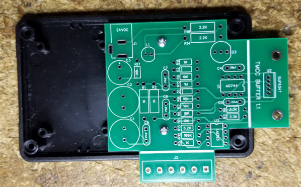
I also got the latest PCB in, after York I'll assemble up a "production" unit and see if I missed anything in the layout. I have discovered it's a bit more difficult to get something that fits precisely into an enclosure with projections than just making a PCB. ![]()
Looks good, I have to mod the case and see if everything works.
Attachments
Images (1)

my club has informed me they would like two of these. you should have my email from past correspondence with you. if not let me know.
GRJ,
I second the previous post. The San Diego 3-Railers Club would like to purchase two of these devices. You can either use the email for BIGDODGETRAIN or mine for the order. I have been out of town for a while and I was just informed of the existence of this device by Dallas Dixon.
bigdodgetrain posted:my club has informed me they would like two of these. you should have my email from past correspondence with you. if not let me know.
Please send me an email on this. I normally just take the profile address, but you don't have one.
BTW Roger, you don't have a profile address either. ![]()
gunrunnerjohn posted:bigdodgetrain posted:my club has informed me they would like two of these. you should have my email from past correspondence with you. if not let me know.
Please send me an email on this. I normally just take the profile address, but you don't have one.
BTW Roger, you don't have a profile address either.
email sent
How's the project coming along, John? Any ETA on the production units?
Not yet, my impending move may delay it for a month or two. I do have what I believe to be the "final" PCB layout, I just have to assemble a couple for some extended testing before pulling the trigger on the full lot.
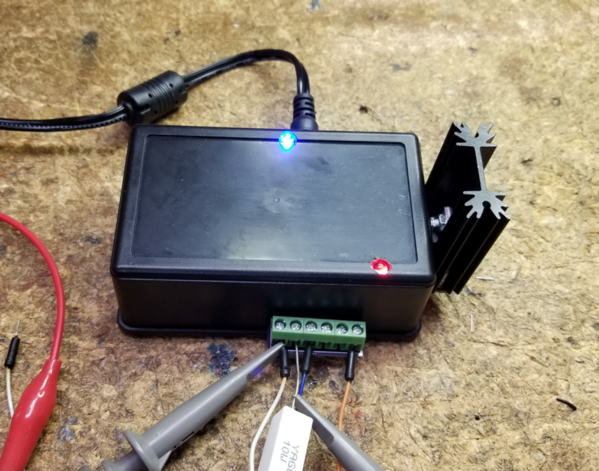
Just finished building what I hope is the "production" model. The completed unit consists of three pieces. Obviously, the actual buffer unit itself, a 24V 1A power brick, and an "earth ground" tap for the command base. The ground is tapped off the outside of the power barrel, this is the connection through the command base power brick to the 3rd wire on the plug. Connecting the buffer is dirt simple.
- Connect the earth ground tap between the command base power and the brick
- Connect the loose wire on the ground tap to the Earth GND terminal on the TMCC Buffer.
- Connect the track signal output wire from the command base to the Base INP terminal on the TMCC Buffer.
- Connect the Boost OUT terminal of the TMCC Buffer to the layout track connection.
The buffer is ready to go. Plug in the 24V power brick, power up the command base, and start running trains.
The three other connections to the buffer box are for DC meter measurements. You can read a relative level of both the BASE DC signal and the BOOST DC output signal referenced to the GND DC pin. These will possibly be useful in the future when we want to compare results between different layouts to evaluate the effects of capacitive loading on the buffer output. Note that these are optional outputs, they don't ever have to be used to effectively use the TMCC buffer. The circuitry that drives these also drives a signal level LED, red is very low or no base signal, off is marginal base signal, and green is a good base signal. I usage note, if there is nothing connected to the Base INP terminal, you may see the signal level indicated as green (good). This happens because stray AC is being fed to the buffer from the floating input, it only happens if there is no connection to the input.
This unit is going out for a real layout test, it'll be tested on the NJ-HR layout. Upon satisfactory test results there, I'll be ready to order parts for these. Stay tuned... ![]()


Attachments
Images (2)


John, looking forward to the results of the testing and getting one of these for my layout
Raymond
Hi John,
Put me down for one of the signal boosters as well.
Maxmn_98
It should be in the hands of the NJ-HR guys now, results to follow. ![]()
John
I received the buffer today and plan to do preliminary testing on Friday and then use it on Sunday for our club's open house.
Bob D.
Looking forward to the production run John!
Sounds good Bob, hope that all goes well. ![]()
Guns,
I just moved into my new home, have not started the new train room layout yet. Moving is crazy these days, make sure you plan everything out in advance and be careful!
Good luck with your move!
all the best
PCRR/Dave
We're taking our time with the move, it'll be over several months. That's the benefit of moving 4 miles. ![]()
We only moved 8 miles. Got the new house almost a full month before we had to be out of the old house. I thought that would be more than enough time...barely made it! ![]() Kind of like the layout always needing to be slightly larger than the space available I guess...
Kind of like the layout always needing to be slightly larger than the space available I guess...![]()
Several months should be much better!!
I'm looking at around 2 months here, then we'll have a few weeks to beat the current house into shape for sale, and hopefully that will close the book. ![]() It's expensive to do it this way, but I'm too old to do same day moves anymore!
It's expensive to do it this way, but I'm too old to do same day moves anymore!
I know what you mean with the one day moves, that's what the extra month was for on our move. We still cut it close though. I think you should have it covered with 2 months!
A ham radio friend of mine took a year. Bought the new house and delivered pickup loads to it over time and set up his basement, ham radio, prewar Lionel train, and storage areas. Rest of the house. Then when the older house was empty, sold it.
Well, a year is a bit much. I don't have 400K loose cash laying around to have an unlimited overlap, so I want to retire the debt as soon as I can sell the old house. ![]()
rad400 posted:John
I received the buffer today and plan to do preliminary testing on Friday and then use it on Sunday for our club's open house.
Bob D.
I will probably get a lot of crap for this but here goes anyway.
the MTH experts at our club are worried that this signal booster will de-grade the MTH signal. What I would like to ask is can you take pictures of the mth remote showing signal strength without the booster in place and again with the booster installed?
thanks
It's a valid point, I have no idea if it affects the DCS signal. One would think not as it's just on one side of the track and dependent on the antenna, but I have no empirical evidence to back that up.
gunrunnerjohn posted:It's a valid point, I have no idea if it affects the DCS signal. One would think not as it's just on one side of the track and dependent on the antenna, but I have no empirical evidence to back that up.
do you believe the New Jersey High Railers can get me what I need?
Probably have to ask them if they're having issues. They've been using a tube version of the amplifier for some time, but I don't know if they've evaluated that extensively.
gunrunnerjohn posted:We're taking our time with the move, it'll be over several months. That's the benefit of moving 4 miles.
When I moved around 20yrs ago the moving company came to give me an estimate, when he asked me where I was moving to I pointed to the house two doors away. At first he thought I was kidding, then he said really, I'll never forget the look on his face.
Art
I could point, but I don't think you can see it from here with all the trees around this house! ![]()
bigdodgetrain posted:rad400 posted:John
I received the buffer today and plan to do preliminary testing on Friday and then use it on Sunday for our club's open house.
Bob D.
I will probably get a lot of crap for this but here goes anyway.
the MTH experts at our club are worried that this signal booster will de-grade the MTH signal. What I would like to ask is can you take pictures of the mth remote showing signal strength without the booster in place and again with the booster installed?
thanks
If I have the time next week I will take the measurements.
Bob D
As some one who has been involved in various aspects of RF engineering (amateur radio, broadcast engineering and systems design) for the past 56 years, I doubt that there will an interference issue. TMCC operates at 455kHz and the DCS operates between about 3.3mHz and 10mHz. There is a significant frequency separation between the systems. Once a booster is available (two on order), I will be able to give an absolute response as I have both DCS and TMCC available on the layout that I am currently constructing.
I don't anticipate any conflicts, and the early testing Dale did with the prototypes of the buffer didn't show up any conflicts, so there's hope. ![]()
John,
I am a member of the " Paradise and Pacific " model railroad club in Scottsdale, Az. I was present @ the layout the day Dale stopped by to demonstrate the TMCC/legacy signal booster. I must say we were ALL very impressed with his devise. Of course we were very sad to hear of his passing. . . . . . .
PLEASE add me to the list to purchase this legacy signal booster.
I am a brand " NEW " OGR forum member, and mag subscriber. . . .
John B.
I think your club is already on the list unless you're looking for one for a personal layout. Keep in mind, this is one of those devices that 98% of TMCC/Legacy layouts probably don't need, it's only large layouts and perhaps exacerbated in multi-layer layouts.
John,
That's correct our club has two maybe three preordered. Some of our members may have placed orders too?
After experiencing this devise first hand. I knew I wanted one. The results were amazing. Besides It's the squirrel in me that wants to stash it away. . . . .Just in case ! I'm so new to this forum, and format, Can you see my email address John ? So you can let me know when they're ready ?
Thanks for your response,
John B.
I can't see an email address in your profile, you have to fill out the profile with a public email address. You can also send me an email to my profile address.
John,
Increase P&P's order to 4 units please,
Thanks,
Ron
gunrunnerjohn posted:... this is one of those devices that 98% of TMCC/Legacy layouts probably don't need, it's only large layouts and perhaps exacerbated in multi-layer layouts.
John, do you anticipate having one on your new layout? I ask that because it seems your layout will be mid-size but not humongous .
Former Member
I have a 58 by 16 layout with the Legacy base right in the middle and I get spotty legacy signal at both ends. It works most of the time but every so often I can do anything with the train until it runs through
ogaugeguy posted:gunrunnerjohn posted:... this is one of those devices that 98% of TMCC/Legacy layouts probably don't need, it's only large layouts and perhaps exacerbated in multi-layer layouts.
John, do you anticipate having one on your new layout? I ask that because it seems your layout will be mid-size but not humongous .
I don't anticipate needing this for my layout.
John. Please add me to the list for the device when ready. Thx. Greg.stack.train@gmail.com
You seem to already be on the list, watch for your email. ![]()
John,
I would like to buy one from you so how do I get to you? Please contact me at kbmkam@aol.com
Kevin
Just a small update as to the status of the project. The testing went reasonably well at NJ-HR, but Bob did have a couple questions that we're still chasing down.
I would like to find one other site to do some testing, obviously it should be one that has significant issues with TMCC without the buffer.
There has also been a delay due to the fact that I'm in the middle of a somewhat messy move in the dead of winter. Being in limbo for a spell is putting a crimp on many of my train-related activities as there are lots of things to do here.
Add Reply
Sign In To Reply
