I have a VA meter - trouble is the settings are confusing -  not intuitive to non-electrical person. I am trying to test various Menards Power adaptors due to reports on the main forum that Menards buildings are frying from one or more of them. I have all 3 models of the adaptors - one of which is no longer made. I am in the process of setting my Menards buildings on my layout and would like to see what's going on before sending juice to them.

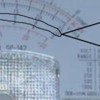
One Power adaptor (model 4006) says it's supposed to put out 4.5 volts and 2000 mamps. My meter has 4 different dial settings for DCV - 2.5, 10, 50, and 250. To start, I set dial to 50  ~ and needle moved; then set dial to 10 - needle moved further; and then to 2.5 and needle moved even further. The meter has 3 different scale ranges for AC & DC volts - see if you can see what I mean in picture (middle range of meter is AC&DC - readings in black font) - the first scale starts at 0, then 1, 2, 3, 4, and 5. 2nd scale starts at 0, 2, 4, 6, 8, and 10. 3rd scale starts at 0, 5, 10, 15, 20, 25. My question is what dial setting corresponds to what graph range on meter, and which dial setting should I set to? And, what do the dial settings reference ~ DCVolts?

As far as measuring mamps - this is even more confusing - meter has dial settings for 0.05, 25, and 250, and when I tested the adaptor for each dial setting the needle pegged each time - guessing that's because adaptor output is greater than any of those dial settings; if accurate then I am guessing my meter cannot measure in the 2000 mamp range?

Thanks for any help.


Attachments

Images (1)
  • HPIM0278
Last edited by Paul Kallus
Original Post

Replies sorted oldest to newest

You use the scale that has a number that is the same as the number on the switch setting...disregarding the decimal point.

You only measure amps by selecting the proper mamp scale which is greater than what you expect from your circuit. You insert the meter leads between the source (transformer) and the load (resistor, bulb, what have you). The other lead of the transformer goes directly to the other side of the load. Then you will read the current (mamps) that the load draws (not the limit of the transformer which is what you refer to...2000mamp). Keep in mind that if your load is a short or draws more current than the meter is capable of measuring, you will usually blow a fuse inside the meter. I am guessing (since your picture has too much glare to read the dials) that your meter has a limit of 250 mamp.

Dale, I don't follow you. The settings on the meter for DCV are 2.5, 10, 50, and 250. Does this correspond to upper voltage readings for that setting?

Stan, I set the dial to 10 and measured the adaptor output - on the scale you circled the needle stopped about 8.5 volts. If that's the right line to read the voltage and its accurate, then the adaptors from Menards are indeed putting out more voltage then they specify - which may be the reason peoples buildings are frying (buildings need only 4.5 volts). Note, reading the scale beneath the one you circled reads 4.5 volts with dial at 10. When I set the dial to 50 and read the scale above the one you circled I get just under 5 volts.

Why is the meter ambiguous on which line of numbers to read as compared to dial setting?

Thanks everyone, still would like to know what I am doing.

Last edited by Paul Kallus
Paul Kallus posted:
...
Note, reading the scale beneath the one you circled reads 4.5 volts with dial at 10. When I set the dial to 50 and read the scale above the one you circled I get just under 5 volts.

Why is the meter ambiguous on which line of numbers to read as compared to dial setting?

Thanks everyone, still would like to know what I am doing.

With the dial at 10, use the scale I circled...ignore the others.

With dial at 50, use the scale BELOW the one I circled (NOT the one above).  Since the one above indicates just under "5", the scale BELOW is indicating just under "1". With the dial set to 50, you interpret the scale BELOW as 0,10,20,30,40,50...rather than 0,1,2,3,4,5 as printed on the face.   Very confusing but that's the way it is!

Not that anyone needs more clutter around the train room, but at your convenience why not get one of those "free" with coupon Harbor Freight digital meters?  I stalked your profile and it appears there are HF stores in PA.  

Paul Kallus posted:

Dale, I don't follow you. The settings on the meter for DCV are 2.5, 10, 50, and 250. Does this correspond to upper voltage readings for that setting?

Stan, I set the dial to 10 and measured the adaptor output - on the scale you circled the needle stopped about 8.5 volts. If that's the right line to read the voltage and its accurate, then the adaptors from Menards are indeed putting out more voltage then they specify - which may be the reason peoples buildings are frying (buildings need only 4.5 volts). Note, reading the scale beneath the one you circled reads 4.5 volts with dial at 10. When I set the dial to 50 and read the scale above the one you circled I get just under 5 volts.

Why is the meter ambiguous on which line of numbers to read as compared to dial setting?

Thanks everyone, still would like to know what I am doing.

You might put your meter on 10 vdc setting and read 3 AA cells in series. Just to check the accuracy of the meter. It should read 4.5 to 5 on the 10 scale.

Paul Kallus posted:
... I set the dial to 10 and measured the adaptor output - on the scale you circled the needle stopped about 8.5 volts. If that's the right line to read the voltage and its accurate, then the adaptors from Menards are indeed putting out more voltage then they specify...

If you are reading the output with an open circuit - no load - then that is about right what you are reading. For an accurate measure, the load has to be close to the rated output(2 amps is the specification you give above in your OP). Any (expected) load will get it closer to 4.5 volts quite quickly.

Stan, with the dial set to 50 the meter reads just 1 volt (from the bottom row of the scale you cited).

Rob - I don't think I can measure with load since the meter probes have to go in the plug and on the outside to make a circuit. Are you thinking 8.5 volts would be normal in the unloaded state? Trying to figure out why some people's Menards buildings are frying.

Thanks, everyone, I'll see if I can find a digital meter.

Paul Kallus posted:

Stan, with the dial set to 50 the meter reads just 1 volt (from the bottom row of the scale you cited).

Rob - I don't think I can measure with load since the meter probes have to go in the plug and on the outside to make a circuit. Are you thinking 8.5 volts would be normal in the unloaded state? Trying to figure out why some people's Menards buildings are frying.

Thanks, everyone, I'll see if I can find a digital meter.

Right.  You should be reading just under 1 on the bottom scale.  That means just under 10 Volts which is what you got using the 0-10V dial setting and middle scale.  Again, it's confusing for sure, but you need to mentally multiply the indicated reading on the bottom scale by 10 when using the 50V DC dial setting.

As I understand it you have the 3-outlet Menards adapter.  I think what Rob is asking is to measure the voltage in one of the unused plugs.  So go ahead and plug in one building.  Now measure the voltage at one of the two unused plugs.


Okay, Stan, I was able to test the load - I plugged in 2 buildings and tested the unused plug: With dial set to 10 I measured around 7 volts; with dial set to 50 I measured just under 1 volt. If I understand you right, I need to multiply by 10 when using the "50 dial setting" ~ so that would put it around 7-9 volts. And, the 10 scale is one for one, so if right then that means the adaptor is indeed putting out more voltage then the 4.5 volts the buildings require. Could this be the reason why the guy on the main forum (he goes by Panther) buildings are frying?

fwiw, I noticed when plugging the adaptors back into the buildings the building lights go on for a second, then off, this with the household plug not plugged in. Does this mean anything, a capacitor in the adaptor maybe?

I have an old HO DC transformer - that I could potentially use for these buildings - it goes up 18 volts DC with lever, I believe. I also have to contact Menards as I have 4 of their adaptors.


Last edited by Paul Kallus

I think you now have your arms around the "multiply the lower scale by 10" thing for the 50 V dial setting!

To summarize your measurements, the no-load adapter voltage is 8.5V DC.  Loaded by 2 buildings it drops to about 7V DC.  That seems a bit high to me for a 4.5V DC adapter where "full" load is 3 buildings.  As to whether or not these voltages damage Menards buildings is something I can't answer.  From what I've read, Menards does not specify operating voltage and current for various buildings...essentially saying to just use their 4.5V DC adapter.

Yes, that brief flash when you plug a disconnected (but recently powered) adapter back into a building is a capacitor inside the adapter discharging its stored energy.

For 2.5 dial setting, use upper scale (marked 0,5,10,15,20,25) and divide the reading by 10. 

For 250 dial setting, use upper scale and multiply the reading by 10. 

The idea is that the adjustment factor makes the full-scale (needle all the way over) reading the same value as the dial setting.

As for a digital meter. Presumably you've built your layout etc. and have been running trains fine without one so obviously it's not a must-have.

In fact, if you just want to mess around with one, I will send you a new Harbor Freight digital meter (the kind you cab get Free with coupon).  Battery included!   I'll even test it first and the postage is on me!  I have a bunch of them. 

ogr hf meter measuring ps1 smoke motor - Copy

I don't see your email in your profile so email me a shipping address to this temporary email address which I'll disable after I hear from you one way or the other:

...

Attachments

Images (1)
  • ogr hf meter measuring ps1 smoke motor - Copy
Last edited by stan2004

That's real nice of you, Stan...my friend's brother said he has one extra from Harbor Freight and will give it to me, so no need to spend postage, thanks for your offer.

Its funny, I found the instructions for the Sperry analog meter I have, and there's nothing useful in it.

I am wondering if I splice the main adaptor power cable and add 10-15 feet of wire - would that reduce the voltage? Probably a formula? I estimate the adaptor has 20 gauge wire, I could use a long run of that or even 18 gauge. I have about 8 Menards buildings that I am just now getting on my layout - just the past year I finished the track work.

Got your email.  I'll answer your question here about the dial setting of the HF meter since we may need to refer to it again.
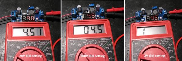
HF digital meter settings

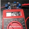
So here's the HF meter measuring the DC output of an eBay voltage regulator module that has been set to 4.5V.  In other threads, I suggest these modules as an inexpensive way to generate regulated DC voltage for Menards and Lemax buildings, Miller signs, etc.  In this case the module even has its own digital meter showing it has been set to 4.5V DC.

Anyway, with the dial setting at 20V (left) the HF meter reads 4.51.  This would indeed be the setting to use for the Menards adapter issue at hand.  If you go to the 200V (middle) setting, note how the decimal point automatically moves for you...no need to mentally adjust the factor.  But note how you lose resolution in the measurement.  This is why you want to use the lowest dial setting that still covers the range of voltages you expect to measure.  This loss of resolution is like your analog meter's needle barely moving if the setting is too large; you can see the needle move but difficult to resolve the value. 

If you go to the 2V (right) setting, the 4.5V overwhelms the meter.  In this case the meter display just shows a "1".  Other meters might display "OF" (OverFlow), or flash, or whatever.  On an analog meter this is where the needle is pinned over to the right side.

More expensive meters have so-called "auto-ranging" capability which automatically chooses the dial setting to maximize the resolution.

As to the wire issue, yes, it's all about formulas.  Look it up in any wire-table and 20 gauge wire has a resistance of about 1 Ohm for 100 feet.  If you are running a 15 ft cable pair or 30 ft of wire that is a resistance of 0.3 Ohms.  Then you use the Ohm's Law which tells you how much Voltage you lose.  Voltage = Current x Resistance.  You need to know the Current (Amps) which, as I've previously lamented, Menards does not seem to publish.  But a reasonable guess is to note that their 1-building adapter is rated at 500mA (or 0.5 Amps) and their 3-building adapter is rated at 2000mA (or 2 Amps).  So let's just go with 0.5 Amps per building.  That means your 15 ft cable will drop/lower the voltage by 0.5 Amps x 0.3 Ohms = 0.15 Volts.  So if the voltage "started" at 4.5V DC, introducing the extra 15 ft of 20 gauge wire means the building only get 4.35 Volts.  My opinion is you shouldn't see a material difference in brightness or behavior for that small a change. 

Note that if you do make such an extension cable you will only see that voltage drop when the current is flowing into the building.  If you measure the voltage at the extended plug (not plugged into the building) you will measure the original voltage.  In other words the current is 0 Amps so the voltage drop from the 0.3 Ohm extension cable is 0 Amps x 0.3 Ohms = 0 Volts.

Finally, the HF meter also has the ability to measure DC current.   I believe we concluded that your existing analog meter only goes up to 250mA (0.25 Amps) which presumably is not enough to measure the building current.  When you get the meter, we can get into the specifics of how to measure building current with the HF meter if you are so inclined.

Attachments

Images (1)
  • HF digital meter settings
Last edited by stan2004

Chuck, nice setup! 

Do you have an eBay (low-cost) source for the black jumper strip shown in your photo - I assume it's 9.5mm / 3/8" centers and it was cut-to-6 positions?

Why the electrolytic capacitor on the right edge of photo which is presumably between the + and - bus on the terminal strip?

And the $64,000 question...why is it set to 4.67V DC? 

Last edited by stan2004
stan2004 posted:

Chuck, nice setup! 

Do you have an eBay (low-cost) source for the black jumper strip shown in your photo - I assume it's 9.5mm / 3/8" centers and it was cut-to-6 positions?

Why the electrolytic capacitor on the right edge of photo which is presumably between the + and - bus on the terminal strip?

And the $64,000 question...why is it set to 4.67V DC? 

I got them from Mouser and cut them with side cutters...one pair that is kind of ruined for soft copper now.

http://www.mouser.com/ds/2/16/Euro7-21095.pdf

I'm using a 12 position with 6 red and 6 black using jumpers.

I found that the Miller signs power supply needed some output capacitance and just left it there when I changed to the ebay ones. 

Ah yes...I was between turns on the trim pot so I left it there. Sometimes I usually tap on the pot to get it to settle in a place that it finds comfortable and stable.

Here's my latest adventure: I picked up the HF meter at lunch break today...it was still new in package, looks to be the same one as yours, Stan. I tried it out first thing when I got home using the "20" setting on DCV and hooked probes to adaptor plug...it read nothing (0.00); I then hooked up a building to one of the plugs and tried again on an unused plug, still nothing.

Then, reverting back to the unloaded state, I started turning the dial and finally when it was on "20m" under DCA I got a reading, about 2.07, then I hooked up one building, and measured, this time the building lights went on and off and the meter readings were jumping all over the place. Not sure what's going on, but something is haywire with the meter. 

I then tried a new C battery - as simple as it gets, or so I thought - it read 0.00 under "20" DCV, but then started moving the dial around the meter until I got to 10A) and it read 1.45. This sounds right, right, cause its a 1.5 volt battery?  Or, is this meter a bust? I know my analog Sperry meter is good, at least the AC part of it, because its AC readings pretty closely matched my Z-4000 transformer digital outputs during track wiring phase of construction.

I like that you guys have voltage regulators, are these off the shelf products, or how hard are they to hook up?

Would an old HO DC transformer with variable control work too? I know I have one laying around somewhere. In theory, I could cut the wires from the Menards adaptors (leaving the plug part in the buildings) and then run all the wire pairs to the little DC transformer, and slowly crank the lever until the lights come on.

Paul Kallus posted:

Here's my latest adventure: I picked up the HF meter at lunch break today...it was still new in package, looks to be the same one as yours, Stan. I tried it out first thing when I got home using the "20" setting on DCV and hooked probes to adaptor plug...it read nothing (0.00); I then hooked up a building to one of the plugs and tried again on an unused plug, still nothing.

Then, reverting back to the unloaded state, I started turning the dial and finally when it was on "20m" under DCA I got a reading, about 2.07, then I hooked up one building, and measured, this time the building lights went on and off and the meter readings were jumping all over the place. Not sure what's going on, but something is haywire with the meter. 

I then tried a new C battery - as simple as it gets, or so I thought - it read 0.00 under "20" DCV, but then started moving the dial around the meter until I got to 10A) and it read 1.45. This sounds right, right, cause its a 1.5 volt battery?  Or, is this meter a bust? I know my analog Sperry meter is good, at least the AC part of it, because its AC readings pretty closely matched my Z-4000 transformer digital outputs during track wiring phase of construction.

I like that you guys have voltage regulators, are these off the shelf products, or how hard are they to hook up?

Would an old HO DC transformer with variable control work too? I know I have one laying around somewhere. In theory, I could cut the wires from the Menards adaptors (leaving the plug part in the buildings) and then run all the wire pairs to the little DC transformer, and slowly crank the lever until the lights come on.

Hopefully you haven't blown the fuse inside the meter.

Anyway, plug the red lead into V^ma and plug the black lead into COM.

Turn the switch to ON.

Then set the range to 20 DCV and read the voltage.

Not to digress, Isn't it amazing how cheap these meters have gotten? Now giveaways. 

Just like the ubiquitous 4 banger calculators you get for pennies. Back in the day I paid dearly for an HP 35 (still have) engineering calculator.  Now I see Texas Instruments that graph, polar/rectangular etc etc., and still does 4 banger math!

Ditto meters, I have a lab quality Fluke that reads to four places pass the decimal.  I paralleled a HF and Fluke and surprised how close the HF read past the decimal point.  Granted not lab precision quality, but HF would be shirt pocket good e'nuff for layout work.

Yes, I had the red plug in the top port, darn it, and read that in the instructions, but when plugged into middle port I am getting consistent results as the analog meter showed, 8.6 volts with no load, and 6.5 volts with one building plugged in. Will try with two buildings plugged in.

One thing I noticed with all 3 plugs plugged into 3 buildings, the lights are super bright, which may get back to the original guy's problem with electronics burning out.

Thanks all! I'll mess around some more.

Paul Kallus posted:

Yes, I had the red plug in the top port, darn it, and read that in the instructions, but when plugged into middle port I am getting consistent results as the analog meter showed, 8.6 volts with no load, and 6.5 volts with one building plugged in. Will try with two buildings plugged in.

One thing I noticed with all 3 plugs plugged into 3 buildings, the lights are super bright, which may get back to the original guy's problem with electronics burning out.

Thanks all! I'll mess around some more.

Generally what happens when you put the leads across a source using the amps plug is that you will blow a fuse inside the meter if there is one. And if there is one, it will usually only render the amps use unusable until you replace the fuse. And who knows, the source might be a high enough impedance or the amps circuit in the meter robust, that the meter is not hurt at all.

Anyway your readings sound reasonable, 4.5 vdc regulated would be better, but it is what it is.

I am starting to lose even more confidence in the Menards Power adaptors...they appear to have been made for something cold the "Menards Gold Line" and Menards adopted them for the O-gauge buildings, not sure what the Gold line is.

Stan, I didn't notice any lessening of brightness from having 1 vs. 2 vs. 3 buildings plugged in, they're all super bright regardless. I can't see how I can measure the load with all 3 plugged in, not easily anyway.

In trying to resolve this conundrum, and short of going the voltage regulator route, and considering Menards has not responded to my question and concern, tell me what you guys think of this idea: I dug up my old Lionel transformer from an 1980s set, wow was that a cheap set, plastic wheels on rolling stock - all plastic cars, made in Mexico as I recall. Anyway, the little transformer has a variable DC output - 0-18 VDC and a constant 19 VAC terminal (that I wouldn't use), and says maximum output is 5.5 VA which I recall is the same as 5.5 watts. I think the Menards buildings draw very little amps, as the adaptors are either 1000 mamps or 2000 mamps, so even at 10 buildings and assuming 2000 mamps per building that's only 0.02 mamps x say 5 VDC ~ 0.1 VA or 0.1 watt, does that sound right? If so, then that little transformer could be used to power all my buildings at a safe load and at a comfortable light level for the visual effect. If affirmative, I could then use the female end plugs in the buildings and cut the wires and send them all to a terminal strip, and then connect the little transformer VDC output to that, and then slowly crank up the little lever until desired brightness was achieved, and never have to worry about frying the buildings electronics? I would have to run one heck of a lot of wire as the buildings are spread around my basement, but using 20 gauge wire wouldn't be so costly. What do you think? Or, is voltage regulators the way to go (I guess a new thread would be in order for that question)?

Paul Kallus posted:

Anyway, the little transformer has a variable DC output - 0-18 VDC and a constant 19 VAC terminal (that I wouldn't use), and says maximum output is 5.5 VA which I recall is the same as 5.5 watts. I think the Menards buildings draw very little amps, as the adaptors are either 1000 mamps or 2000 mamps, so even at 10 buildings and assuming 2000 mamps per building that's only 0.02 mamps x say 5 VDC ~ 0.1 VA or 0.1 watt, does that sound right? If so, then that little transformer could be used to power all my buildings at a safe load and at a comfortable light level for the visual effect.

I believe your thinking derailed Paul.

If we used your example of each building drawing 2000mamps (which really same as 2 amps) each, then you would have needed a 20 amp supply!

If we use the transformer  5.5VA  rating (which it isn't equivalent to watts, but will assume value for argument sake) and adapters rated 4.5V, then you could safely draw about 1.2 Amps or 1200 mA from transformer without harm.  So 10 buildings could draw 120 mA each, or any current combinations until reaching 1200 mA maximum.  You would need to measure each building current especially if it uses a Miller Engineering style electrolumenescent sign (their inverter power supply draws significant current I found).

Hope this helps.

Last edited by rrman

RRMAN, I see your point, seems hard to fathom that each building would draw 2 amps, though, given they're LEDs, but that's what the power adaptors specify. On the little transformer at 5.5 VA - I thought volts x amps = watts? Good point on the buildings that have the Miller engineering signs, am not sure which buildings they are, though.

As I was laying in bed last night I realized something I overlooked - the Menards buildings all have different #'s of LEDs, some only have 1 or 2, while the Power plant must have close to 20. The 3 buildings I've been measuring with meter only have 1 or 2 each (and the 3 buildings that the original guy who said his burned out were all minimal lights as well). Wouldn't this then be the reason why the voltage load is still high in my measurements? Assuming I am correct, could I cut the main feed from the power adaptor (see photo) and send it to a small terminal strip (hot and common). Then, cut the 3 feeder plugs (and remove the plastic junction) and re-connect the 3 feed plugs + additional feed plugs (that I'd have to cannibalize from other adaptors) to the terminal strip and to as many buildings as it takes until the load comes closer to 4.5 volts? These are wired in parallel in original state, right? Or, would this mess up the amperage output of the adaptor? Does this make sense? I'd be cutting the wires at the location the pens in the photo show - and removing the junction - it'd be replaced with a terminal strip that could output additional plugs to 4, 5, or x # of buildings needed to bring voltage to 4.5 VDC.

Attachments

Images (1)
  • HPIM0281
Last edited by Paul Kallus

I love the little Harbor Freight meters, but they do have a chronic manufacturing flaw.  The metal rings into which the test probes plug are mounted on a narrow finger branching off the main circuit board.  This little finger is supposed to be supported by a small plastic latch that provides mechanical support to hold the finger in place when you insert the test leads.  Unfortunately, many of those finger boards have either too much solder or the end of the 10 amp wire shunt is too long, and that keeps the latch from engaging the finger.  When you try to insert the test leads, the finger board bends away inside and you get no connection.

I remove the meter from the blister pack and insert the leads before I leave the store, using the ohms scale to check for continuity.  You can also look into the test lead hole after you try to insert the leads to see if the metal rings are still up toward the top of the holes and not pushed way down.   

I have had maybe 4 or 5 meters with this problem, including one just 2 weeks ago.  No problems with exchanging bad units.  This problem has been around for a couple of years.

ogaugenut posted:

I have the 3 outlet Menards power supply.  I plugged it into my new Menards light and power, it light up.  Tested the voltage at a second outlet from the supply and got 7.05 volts.  Won't this burn out the LEDs prematurely?

Bill

It depends if the electronics in the building has a current regulated supply for the LEDs. If not, I would think that you might want to use a 4.5 vdc regulated supply. One question, do they get brighter if the voltage goes up and dimmer if the voltage goes down. You can check this by plugging in additional buildings to your power supply which will reduce the voltage because of loading.

Chuck and others, would it be ok to hook up say 4, 5, even 6 Menards buildings to a terminal strip that was powered by one of the Menards 4.5 VDC adaptors? The # of buildings would be determined by measuring the voltage load as I added buildings to the terminal strip, that is until the voltage was around 4.5 VDC. I guess I'd also have to measure the amp load, right, as it shouldn't exceed the adaptors output?

I'd follow your advice on using a regulated VDC supply but have no clue as to what to buy let alone install it.

I just read on the main forum another poster who reported failures in his Menards building lights.


Last edited by Paul Kallus
Paul Kallus posted:

I am starting to lose even more confidence in the Menards Power adaptors...they appear to have been made for something cold the "Menards Gold Line" and Menards adopted them for the O-gauge buildings, not sure what the Gold line is.

Not sure this is relevant, do these power adapters run their Ceramic Christmas Village buildings?

Paul Kallus posted:

Chuck and others, would it be ok to hook up say 4, 5, even 6 Menards buildings to a terminal strip that was powered by one of the Menards 4.5 VDC adaptors? The # of buildings would be determined by measuring the voltage load as I added buildings to the terminal strip, that is until the voltage was around 4.5 VDC. I guess I'd also have to measure the amp load, right, as it shouldn't exceed the adaptors output?

I'd follow your advice on using a regulated VDC supply but have no clue as to what to buy let alone install it.

I just read on the main forum another poster who reported failures in his Menards building lights.


I'm guessing here but I would expect the voltage to go down to about 4.5 vdc, the rated voltage on the wall wart, when you draw nearer to the 2 amps. So no need to measure the current. And the wart will get warm, but not hot.

cjack posted:
ogaugenut posted:

I have the 3 outlet Menards power supply.  I plugged it into my new Menards light and power, it light up.  Tested the voltage at a second outlet from the supply and got 7.05 volts.  Won't this burn out the LEDs prematurely?

Bill

It depends if the electronics in the building has a current regulated supply for the LEDs. If not, I would think that you might want to use a 4.5 vdc regulated supply. One question, do they get brighter if the voltage goes up and dimmer if the voltage goes down. You can check this by plugging in additional buildings to your power supply which will reduce the voltage because of loading.

Now to get all technically:

Rule of thumb for Leds is whites are about 3.3V voltage drop and draw about 20mA nominal. Others have different  voltage drops dependent on color and diode materials.

That said a resistor is used to current limit Led voltage, because LEDs for the most part tend to keep a constant diode voltage drop, thus the resistor has to "take up the slack".  The Menards buildings use very small surface mount resistors that don't have alot of surface area thus low milliwatt power dissipation.

So lets say we have 4.5V  voltage and one 3.3V @ 20mA LED.  The resistor is (4.5V-3.3V)/0.020A = 60 ohms. 

Power dissipated is (0.020A * 0.020A) * 60 ohm = 0.024W well within the resistor dissipation

Retaining the resistor value lets up supply to 7,05V

(7.05V - 3.3V)/60 ohm = 0.0625 A.

Resistor power is now ( 0.0625* 0.0625) * 60 ohm  = 0.23W !! Almost a 10 fold power dissipation and after short while the resistor will burn open unless designers properly sized resistor wattage worst case.

This would explain, all things being equal, why some Menards building LEDs fail.

Any buildings of mine are powered from a regulated 4.5V supply, because you can't repair the all glued together darn things!

The Menards supplies are the cheapy transformer, diode and maybe capacitor combo.  The more transformer iron the better voltage regulation and closer the voltages stay the same with varying current load.  The 4.5V is achieved when fully loaded, lighter the load higher the voltage from the Menards adapters.  If you use an HO supply you can adjust the voltage to be 4.5V as long as all the loads remain connected. Adding or removing loads will require adjustment.  And of course items with lamps and motors that go on and off will yo-yo the supply voltage.

Clear as mud, right??  

rrman posted:
cjack posted:
ogaugenut posted:

I have the 3 outlet Menards power supply.  I plugged it into my new Menards light and power, it light up.  Tested the voltage at a second outlet from the supply and got 7.05 volts.  Won't this burn out the LEDs prematurely?

Bill

It depends if the electronics in the building has a current regulated supply for the LEDs. If not, I would think that you might want to use a 4.5 vdc regulated supply. One question, do they get brighter if the voltage goes up and dimmer if the voltage goes down. You can check this by plugging in additional buildings to your power supply which will reduce the voltage because of loading.

Now to get all technically:

Rule of thumb for Leds is whites are about 3.3V voltage drop and draw about 20mA nominal. Others have different  voltage drops dependent on color and diode materials.

That said a resistor is used to current limit Led voltage, because LEDs for the most part tend to keep a constant diode voltage drop, thus the resistor has to "take up the slack".  The Menards buildings use very small surface mount resistors that don't have alot of surface area thus low milliwatt power dissipation.

So lets say we have 4.5V  voltage and one 3.3V @ 20mA LED.  The resistor is (4.5V-3.3V)/0.020A = 60 ohms. 

Power dissipated is (0.020A * 0.020A) * 60 ohm = 0.024W well within the resistor dissipation

Retaining the resistor value lets up supply to 7,05V

(7.05V - 3.3V)/60 ohm = 0.0625 A.

Resistor power is now ( 0.0625* 0.0625) * 60 ohm  = 0.23W !! Almost a 10 fold power dissipation and after short while the resistor will burn open unless designers properly sized resistor wattage worst case.

This would explain, all things being equal, why some Menards building LEDs fail.

Any buildings of mine are powered from a regulated 4.5V supply, because you can't repair the all glued together darn things!

The Menards supplies are the cheapy transformer, diode and maybe capacitor combo.  The more transformer iron the better voltage regulation and closer the voltages stay the same with varying current load.  The 4.5V is achieved when fully loaded, lighter the load higher the voltage from the Menards adapters.  If you use an HO supply you can adjust the voltage to be 4.5V as long as all the loads remain connected. Adding or removing loads will require adjustment.  And of course items with lamps and motors that go on and off will yo-yo the supply voltage.

Clear as mud, right??  

Clear. That's a good explanation of the issues involved here. We need a good rather inexpensive source of regulated, say 3 amp switching, supplies. That just need AC in and DC out. I like the one I made, but I'm  not in the manufacturing business. It has voltage and current readout, and that is important so you know what you're doing with these somewhat expensive Miller and Menards signs.

I'm still curious on the voltage drop of the Menards 4006 adapter as you add buildings.  Before you go cutting wires and making terminal strips or whatever, do the supplied 1-to-3 way cable separate?  If so, what kind of connectors are used?

4006 3-way adapter

You said you have 4 of these 3-output adapters?  If it comes apart at the arrow and has the "right" connector arrangement, I'm thinking you can take the 1-to-3 way splitter cabling from an unused adapter and attach it to one plug of the powered adapter.  You now have a 5-output adapter...2 plugs with original length, 3 plugs with essentially double-length.  Now you can measure the voltage with 1,2,3,4 buildings attached. 

There are also all kinds of splitter cables available that you could attach to one of the 4006 outputs and make it into 2,3,4,etc. outputs.  And even extension cables.

splitter y extenstion cables 99 cents and up

So if indeed your buildings are "low power" and you can operate more than 3 per adapter, using some combination of inexpensive splitter and extension cables is an option.  Cutting wires, splicing connections, possibly soldering, etc. can be a tedious affair.

If you are going to mess with the HO transformer, a screw-terminal adapter like this can come in handy...possibly in conjunction with a splitter-cable.

male screw terminal coax barrel adapter

I see there are a few other threads on this issue.  Has anyone received a reply yet from Menards that clarifies the technical specs of the adapter and their buildings?  For example, the Woodland Scenics buildings I've seen state the current requirements for their buildings (50 mA, 80 mA, etc.).  Obviously this goes a long way toward choosing a suitable power source.  If you have 3 buildings each having only have a few LEDs in them, it does seem odd that Menards' suggested solution is a 3-output 2000mA adapter (unregulated).

Attachments

Images (3)
  • 4006 3-way adapter
  • splitter y extenstion cables 99 cents and up
  • male screw terminal coax barrel adapter

Hi Stan, I'll check to see if I can follow your suggestion on using the other adaptors. What web address sells all those nice extension cables? That's neat.

As far as I know Menards has not responded to the general forum inquiry, and they haven't gotten back to me on my question. Their website for each building only states that the buildings take a 4.5 volt adaptor. Unfortunately, I've thrown away all those clamshell plastic containers the buildings came in...if anyone still has them can you share what the voltage amperage ratings are for the buildings you have, assuming their even listed on the packages. Thanks.

And, thanks to everyone in their sharing of electronics information. Maybe we'll be able to help others too.

Last edited by Paul Kallus

The splitter cables, extension cables, and screw-terminal adapter examples I've referred to are from eBay.  For example, just search eBay for "2.1mm splitter cable" and you'll get thousands of choices most from Asia.  You can narrow it down to "US Only" sellers which improves on the ~3 week delivery time from Asia though prices adjust upwards.  I guess the point is this style of connector is used in many electronic products so it's likely there are products that will apply to Menards buildings. 

While waiting for Menards to clarify the apparent compatibility issues between their buildings and adapters, are you "done" with the original topic of measurement technique(s)?  I think there are 2 separate albeit related issues...1) how to measure the voltage and Amps (per title of this thread) and 2) what to do about it.

I think you have the voltage measurement issue under control.  Measuring current is a different matter.  Assuming your HF meter's current measurement mode is functional are you interested in going down that path?

Stan, I think I am good on voltage measurement with the two meters I have, thanks again.

For current measurements, I am unsure what to do. I have 3 different Menards transformers: 2 are rated at 4.5 volts and 1000 mamps each (models 4002 (3 plug) and 4005 (single plug); the newer model (4006 - 3 plug) is rated at 4.5 volts and 2000 mamps. The reported problems with burned out buildings have been reported on that newer model. Previous (about a year ago) reports were that the older 4002 3-plug unit put out "unregulated" voltage. I contacted Menards last year about those reports and Ray from Menards said he hadn't heard of any problems with them, and there were thousands sold. He said the only changed suppliers and the 4006 model replaced the 4002, that's all.

Is there any need to measure current load once I get the plugs wired into each other or a terminal strip? If I understand right, the buildings will only draw enough current each needs, and that the Menards transformers won't put out excess current (but obviously will on voltage). If it is a good idea to check current then I use the meters to see what it is, once I get the wiring fiasco under control (will try to do that this weekend and I am off work tomorrow).

Paul, given my explanation above (somewhere) of how LED resistors could go poof, keeping voltage under control should be more important.  I would recommend searching flea bay for 4.5V regulated supplies with 2-3-4 amp rating. There are two styles either will work for Menards and anything else (Lemax houses and animations) requiring 4.5VDC.  One type is linear which has big transistors controlling voltages but get warm (or hot), and switchers that run cooler. Usually tell switchers because they are relatively small and compact while having a large current output at designed voltage and can usually be plugged into wall outlet (cavet, read specification or ask seller what type technology is used. If don't know then skip them and move on).  Linears are larger bulkier and generally can't be plugged directly into wall outlet like a switcher can.

My 2.5 cents.

PS I am starting another thread for the electrical gurus about USB chargers

Last edited by rrman
stan2004 posted:

I'm still curious on the voltage drop of the Menards 4006 adapter as you add buildings.  Before you go cutting wires and making terminal strips or whatever, do the supplied 1-to-3 way cable separate?  If so, what kind of connectors are used?

4006 3-way adapter

You said you have 4 of these 3-output adapters?  If it comes apart at the arrow and has the "right" connector arrangement, I'm thinking you can take the 1-to-3 way splitter cabling from an unused adapter and attach it to one plug of the powered adapter.  You now have a 5-output adapter...2 plugs with original length, 3 plugs with essentially double-length.  Now you can measure the voltage with 1,2,3,4 buildings attached. 

There are also all kinds of splitter cables available that you could attach to one of the 4006 outputs and make it into 2,3,4,etc. outputs.  And even extension cables.

splitter y extenstion cables 99 cents and up

So if indeed your buildings are "low power" and you can operate more than 3 per adapter, using some combination of inexpensive splitter and extension cables is an option.  Cutting wires, splicing connections, possibly soldering, etc. can be a tedious affair.

If you are going to mess with the HO transformer, a screw-terminal adapter like this can come in handy...possibly in conjunction with a splitter-cable.

male screw terminal coax barrel adapter

I see there are a few other threads on this issue.  Has anyone received a reply yet from Menards that clarifies the technical specs of the adapter and their buildings?  For example, the Woodland Scenics buildings I've seen state the current requirements for their buildings (50 mA, 80 mA, etc.).  Obviously this goes a long way toward choosing a suitable power source.  If you have 3 buildings each having only have a few LEDs in them, it does seem odd that Menards' suggested solution is a 3-output 2000mA adapter (unregulated).

The barrel connector size for the Menard's buildings is 5.0mm o.d x 2.5mm i.d.  I've purchased a few at Radio Shack  #274-1568.  Can't really help you with other spec's as I have a 5V DC bus (computer power supply) around the layout and hook up to it using a single dropping diode.  I do the same with all of the Miller Engineering signs.  Hope this helps a bit.

Bruce

SandJam posted:

...They may well be able to handle much higher voltages than what the adapter is labeled.  

Exactly.  This is why I'm most curious to hear what Menards has to say.  I've got to believe they have way more data points (e.g., number of returns or complaints) than the anecdotal reports here.  So if they have sold thousands of these adapters and buildings, there is probably more to the story than we are seeing. 

Earlier it was asked if the brightness of the buildings changed as the number of buildings attached changed.  Apparently the buildings had constant brightness even with changing voltage; this is an indicator that the buildings were designed to handle higher/varying voltages.

"Earlier it was asked if the brightness of the buildings changed as the number of buildings attached changed.  Apparently the buildings had constant brightness even with changing voltage; this is an indicator that the buildings were designed to handle higher/varying voltages."

I've been experimenting today and I put two buildings on the single adaptor (110 ma).  The voltage dropped to 4.5 and the lights were clearly dimer.

Bill


stan2004 posted:
BruceT47 posted:

The barrel connector size for the Menard's buildings is 5.0mm o.d x 2.5mm i.d.  I've purchased a few at Radio Shack  #274-1568...

OK.  Then my references to 5.5mm / 2.1mm are incorrect and any connectors/cables/adapters need the dimensions Bruce says.  Size matters !

I'm using 5.5/2.1 mm. They seem to work fine. And are the same ones that Miller Engineering uses.   Also 274-1568 doesn't come up on Radio Shack's site.

cjack posted:
stan2004 posted:
BruceT47 posted:

The barrel connector size for the Menard's buildings is 5.0mm o.d x 2.5mm i.d.  I've purchased a few at Radio Shack  #274-1568...

OK.  Then my references to 5.5mm / 2.1mm are incorrect and any connectors/cables/adapters need the dimensions Bruce says.  Size matters !

I'm using 5.5/2.1 mm. They seem to work fine. And are the same ones that Miller Engineering uses.   Also 274-1568 doesn't come up on Radio Shack's site.

OK.  I just checked one of the buildings and you are correct that the 5.5/2.1 MM does fit and is likely the best selection.  The 5.0/2.1 MM also seems to fit.  It looks like the heavy side spring loading on the female connector allows the 5.0 / 2.5 MM I.D to work also, but admittedly not the best fit.  I just grabbed one out of the parts bin, hooked it up and the lights came on so I stuck with it on later buildings.  

I googled the part # I posted and it came up as a valid RS part, however it is in their old red / white plastic package so the number may now be obsolete.

I'll definitely go with the smaller 2.1 MM I.D. in the future!  Don't want the lights to start flickering when it gets windy.


ogaugenut posted:

"Earlier it was asked if the brightness of the buildings changed as the number of buildings attached changed.  Apparently the buildings had constant brightness even with changing voltage; this is an indicator that the buildings were designed to handle higher/varying voltages."

I've been experimenting today and I put two buildings on the single adaptor (110 ma).  The voltage dropped to 4.5 and the lights were clearly dimer.

Bingo.  Thank you ogaugenut for the new info!

With 2000 mA 3-way adapter, 2 buildings have an output voltage of 5.83V.

With 1000 mA 1-way adapter, same 2 buildings have an output voltage of 4.5V and dimmer.

Building brightness is indeed dependent on input voltage above 4.5V.  Albeit a sample of 1, the stars are starting to align.  I don't have any Menards buildings but (in my opinion) you guys that do should be wary of using the 3-way adapter with your buildings until you hear from Menards.  Please post here what they have to say about this! 

Last edited by stan2004

Having taken off today I was able to get 5 buildings wired to a terminal strip powered by one Menards 4006 adaptor (2 amp) and the voltage at the strip only dropped to 6.4 volts - lights were still fairly bright! All five buildings however only have 2-3 LEDs per structure, thus its not a tremendous load. I am measuring voltage at the right spot, right? Or, should I measure at the furthest away building plug?

My next job will be with the Power station - that building alone has at least 20 LEDs ~ which is roughly equivalent to the load of 7-10 regular structures. It is on the other side of the basement, however, so it'll probably have to have its own power source. I got plenty of Menards adaptors left, running out of barrel jacks, though, but Radio Shack is not too far away.

.


Last edited by Paul Kallus

As discussed earlier, for the amount of current (minimal) your 2-3 LED buildings consume, the voltage difference (drop) from the terminal strip to the building plug will be negligible for 15 ft of wiring - under 0.1 Volts.

I believe ogaugenut said he also has the Menards Power Station.  Based on his info and your latest measurements, I'd guess your 5 buildings use less than 25% of the capability of the 4006 adapter.  The voltage drops to the desired 4.5V DC when you draw about 100% of the adapter capability.   rrman did some nice calculations earlier and I'd say you're driving your LEDs twice as hard as they were designed for.  Do you happen to have any of the 1000mA adapters?  Simply using one of those for your 5 buildings will probably yield a voltage of around 5V which would drop brightness and make me more comfortable.  Otherwise, since you apparently cut the cords and are using terminal strips, can you add a few components to the strip?  Specifically you could add some 25 cent diodes to drop the DC voltage about 0.7 Volts per diode...so 3 diodes would drop about 2 Volts and you'd be near 4.5V.  Or you can add a low-voltage incandescent bulb or bulbs to the terminal strip to draw current and hence lower the voltage.

My understanding of the origins of 4.5V DC "standard" for buildings and accessories is from using 3 x 1.5V batteries.  Remember how these adapter used to be called "battery-eliminators"?   Anyway, 4.5V DC regulated adapters are hard to find...whereas 5V DC regulated adapters are everywhere and inexpensive since 5V is a standard voltage used in computer/electronic gadgets.  So if messing with diodes or other voltage reduction ploys is messy, I'd rather see you use a low-cost 5V adapter than over-driving your buildings with 6.8V.

Last edited by stan2004

Stan, last night I found that I have 2 additional small Menards buildings I can gang onto the existing 5 building strip - that would make 7 buildings on the strip. I also have Menards 1 amp adaptors. Am wondering if I should swap out the 2 amp adaptor first for the 1 amp or add the 2 other buildings to 2 amp supply to see what the voltage reads, if its still high then swap out for 1 amp. Actually, I am not sure about where to place the 2 other buildings, so maybe I should swap out the 2 amp...have to do some city planning.


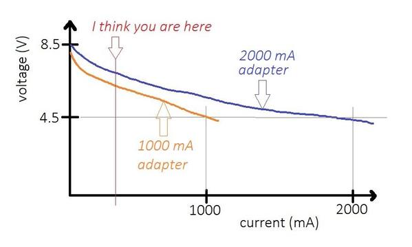
I think both 1000mA and 2000mA adapters will still put out more than 4.5V DC even after adding 2 "small" buildings - "small" being only a few LEDs as opposed to the ~20 LED Power Station.  Here's what I think is going on:

menards adapter speculation

As you've measured, the voltage drops as you add buildings which of course adds load current.  The adapters drop to the specified 4.5V when the load reaches the adapter's nameplate current.   For the same set of attached buildings, the 2000 mA will put out a bit more voltage than the 1000 mA adapter.

As shown in the crude plot, I believe you are operating well below 1000 mA.  And even adding two "small" buildings will only move you right a small amount so that your voltage will still be well above 4.5V with either adapter.

If you don't want to complicate matters with eBay regulator modules, diodes, dummy lamp loads, whatever, then I'd use the adapter that gets you closer to 4.5V when the desired set of buildings is attached.

Not to 2nd guess Menards, but after reading the other OGR threads about the building light failures, it seems they have a bit of a conundrum.  As you've already pointed out, some buildings can have 10 times the number of LEDs as another building.  And it appears they now have buildings with "neon" signs which have different electrical characteristics than LEDs.  I am now even more curious as to their response to your inquiry! 


Attachments

Images (1)
  • menards adapter speculation
Last edited by stan2004
cjack posted:

And as far as second guessing the manufacturer goes, I think the manufacturer is smart enough to realize that this is a treasure chest of valuable research being done by competent pro bono engineer enthusiasts instead of expensive consulting engineers.

But Chuck, is Menards listening and using this data for planning?

Anymore, switcher technology is becoming "dirt cheap". Switcher ICs and "cookbook" schematics readily available, Just a torrid coil or transformer, capacitor, a MOSFET or two and voila, done. (OK that was simplistic but you get the idea.)  That is what I figure is inside those small cube plug in USB chargers that put out an amp or so, and I suggested (in another thread) might be a good source for powering a couple Menards LED only buildings.

 As an aside when I volunteered at a computer rebuild center, there were totes of switcher supplies from small wall warts to some big boys with serious amperages.  When that center closed I grabbed all the switcher supplies I could reasonably carry home or might ever need, including ubiquitous computer tower/desktop ones.

Paul Kallus posted:

Stan, last night I found that I have 2 additional small Menards buildings I can gang onto the existing 5 building strip - that would make 7 buildings on the strip. I also have Menards 1 amp adaptors. Am wondering if I should swap out the 2 amp adaptor first for the 1 amp or add the 2 other buildings to 2 amp supply to see what the voltage reads, if its still high then swap out for 1 amp. Actually, I am not sure about where to place the 2 other buildings, so maybe I should swap out the 2 amp...have to do some city planning.


Paul, You could probably safely use 20 mA per LED as a rule of thumb value, then add up all the LEDs of your buildings to see approximately how much current is drawn, recalling 1000 mA is = 1Amp.  So in this case ~50 LEDs would reach the adapters 1 A limit.  The "neon" sign power supplies current is much higher and seems to vary alot so don't have a rule of thumb value to factor in.

Or get fancy, measure building current draw at 4.5V and divide by number of LEDs (digital meter best bet here than analog needle). Repeat for one or two others and average the results. Probably will fall between 20-25mA range.

So curiosity led me to look at the Menards site and pasted together the "electrical" characteristics of different buildings and there's quite the range!  The Quonset Hut appears to have only 2 LEDs - perhaps like Paul's "small" buildings.  I see the Power Station which has been discussed with 20 LEDs and apparently a "neon" sign too.  And then the Train Station with 40 LEDs in the form of strip lights whatever that means.   And I saw a few buildings like the Farm Supply with an operating fan - perhaps some small motor? 

menards buildings led neon fan

So one "building" can have 20 times the number of LEDs as another building!   And then there are the wildcards of the "neon" signs and the rotating fans. 

With this much variation, it makes me wonder if it can be as simple as saying to use the 1-plug (unregulated) adapter for 1-building and the 3-plug (unregulated) adapter for 3-buildings?!i wonder

Attachments

Images (2)
  • menards buildings led neon fan
  • i wonder

All good points and advice.

I only have one package left (threw out all the others as they are the plastic clamshell junk) - "GrandPa's house" and it says power with 4.5 volt supply. I then checked Menards site and each building states the 4.5 volt supply as well. Simple logic dictates to supply them with as close to 4.5 volts as possible. Had I known the pitfalls of their power adaptors I would have never ordered them, and just gone with my old HO DC transformer, which I actually still may do.

Thanks again to everyone for their constructive input. I actually have two more buildings on order with Menards (had a $20 gift card that was burning a hole in my wallet). I expect them next week, and hope to have the power supply situation squared away this time next week.


Stan and others, only the older 4002 3-way adaptor (1 amp) comes apart like your photo shows. The newer 4006 (2 amp) version has the 3 plugs permanently connected to the main feeder wire - and that feeder wire comes apart from the transformer.

fwiw, I swapped out the 4006 transformer for the 1-amp version and sure enough the voltage came down to around 5 volts, lights are what I call normal brightness. That's for 5 buildings.

OK guys, thanks for detailing that.  I was thinking of someone who might have an unused 4.5V or 5V regulated cell-phone charger or adapter from some gadget.  These would have just one connector output and I thought if the connectors were compatible they could at least re-use the 1-to-3 way splitter cable from the unregulated Menards adapter and be back in business with a known voltage...in my opinion of course.

Last edited by stan2004

I did that Stan due to the very problems cited here.  Too much voltage - almost twice as much coming from Menards with the 3 pig-tails.

Even with all the pig-tails used....still way over 4.5


I used the only one I had on hand....a Lemax 500mA.

I spliced and soldered it in (polarity matched) to the lead of the 3 pig-tails.

I'm running the burned out Engine Building (maybe 7 LEDS - no sign) and the Hermans factory (10 LEDS and the sign) with a free pig-tail.  The free pig-tail measures about 4.4 volts with the other 2 buildings fully operating.

I feel I could probably run another small building in it and still be in range but pretty close to max on this adaptor.

The building I have coming is the Chippawa with the turning fan (small motor) and a few LEDS.

What do you think that little motor might draw?

My set up with the Lemax has been running off and on now for over a week with no issues.

Dave

A small DC gearmotor assembly slowly driving a light-weight fan blade should draw no more than 50 mA...or the equivalent of about 2-3 LEDs.  If your 500 mA Lemax adapter (presumably unregulated) has already dropped to 4.4V with your existing loads I think you are indeed max'd out.

If Lemax products are readily available to you I see they have what appear to be regulated 3-output 4.5V adapters.  It's fascinating they describe it as a "switching mode" power adapter which tells a techno-type that it's regulated but I wonder what it means to a typical customer at Michael's Craft Store where I find Lemax stuff!  Yet, on their website I couldn't find the mA rating of this though on Amazon I found what appears to be the same product and it says 1000 mA.

lmeax switching adapter

But if you already have the splitting cabling in place and just need a more than 500 mA eBay has many 4.5V 1000mA regulated adapters for $2-3 free shipping from Asia...or $5-6 for a US-based seller.

1000mA regulated adapters


Attachments

Images (2)
  • lmeax switching adapter
  • 1000mA regulated adapters
Last edited by stan2004

Thanks Stan

I had checked out the 3 way ones on Michael's site and think they would work fine.

The only Menards adaptor I have/had is the 3 way one which put out twice the stated value.

I'm taking delivery this week of 2 more Menards buildings and 2 Menards individual adaptors.  (each for use on one building only).  I will measure the output of both these singles and report back.

After reading multiple posts about the power switch adapters I'm totally confused.  It seems lots of people have different ideas on what is causing this problem of not lighting, dimming etc.  We really do need to hear from Mark at Menards as to what's causing this problem.  Lighting a building without the fear of frying something or no lights at all shouldn't take up this much time on the forum.  

Paul

Harleylito posted:

After reading multiple posts about the power switch adapters I'm totally confused.  It seems lots of people have different ideas on what is causing this problem of not lighting, dimming etc.  We really do need to hear from Mark at Menards as to what's causing this problem.  Lighting a building without the fear of frying something or no lights at all shouldn't take up this much time on the forum.  

Paul

Well I pointed out in earlier entry with formulas, how higher adapter voltage could fry the small resistors that current limit the LEDs.  I and others then said the best choice is a constant voltage adapter that puts out steady regulated 4.5VDC.  The best are the switcher or switch mode adapters or a linear supply outputting that voltage. 

I don't believe that Mark or Menards has a electrical engineer on staff to answer this adapter question.  They can only go on what their Chinese supplier tells them.  Sort of like taking the diagnosis of doctor in a specialty area you are unfamiliar with.

Really, Menards is getting great pro-bono help/advice from electronic engineers and technicians on this thread and elsewhere who "have been there, done that", fried and smoked parts and designs.

Harleylito posted:

...We really do need to hear from Mark at Menards as to what's causing this problem.  Lighting a building without the fear of frying something or no lights at all shouldn't take up this much time on the forum. 

wasting time

Have you sent an inquiry to Mark at Menards?  From various comments on different threads it's not clear to me if Menards sees this as just a normal return rate or warranty repair...or whether they indeed see it as a product defect or something systemic.   If most of the returns/problems are going on at the bricks-and-mortar stores I would think it could take some time for field data to make it back to headquarters.

I've already put the cart-before-the-horse and jumped to a conclusion!  They need to replace their existing adapters with regulated versions just like Lemax did for their 4.5V lighted products.  It looks like Menards uses the Masterforce private label for their electronic products.  I figure it would take months to put the pieces in place, ramp up production in Asia, get product to US shelves, etc.

Attachments

Images (1)
  • wasting time
John H posted:

I have a building on the way. I was planning on using a PC power supply's 5VDC with a series diode. I think I''ll stick with that plan.

I assume by this statement, you mean you WILL use a PC supply.  If so, I would add a 1 or two amp fuse in series with hot wire.  Those PC supply +5VDC can really source the current!

Thanks, RRMAN. I have all my LED lit buildings on a 3A resettable breaker. I use a digital DC volt/amp meter on each circuit, so when I get up to 2500ma or so I start another circuit. I'm using the 12VDC tap of the power supply for them, with mostly LED strip lighting conversions. 5 meters of them only draw 2 amps, and I have almost used one up, so I have more on the way. I'm using 22awg wire so I limit the circuit to that. It doesn't protect each individual building, but should cover a short.

rrman posted:
John H posted:

I have a building on the way. I was planning on using a PC power supply's 5VDC with a series diode. I think I''ll stick with that plan.

I assume by this statement, you mean you WILL use a PC supply.  If so, I would add a 1 or two amp fuse in series with hot wire.  Those PC supply +5VDC can really source the current!

Not sure I understand this?  Is the fuse a backup in the event the internal protection fails?  I can ground a couple of pieces of magnet wire together on any of the outputs and my unit shuts down instantly for 3-5 minutes. Thanks for any additional input!

Bruce


BruceT47 posted:
rrman posted:
John H posted:

I have a building on the way. I was planning on using a PC power supply's 5VDC with a series diode. I think I''ll stick with that plan.

I assume by this statement, you mean you WILL use a PC supply.  If so, I would add a 1 or two amp fuse in series with hot wire.  Those PC supply +5VDC can really source the current!

Not sure I understand this?  Is the fuse a backup in the event the internal protection fails?  I can ground a couple of pieces of magnet wire together on any of the outputs and my unit shuts down instantly for 3-5 minutes. Thanks for any additional input!

Bruce


Hi Bruce,

Suggesting using an external fuse on each of John's 5V lines.  If your PC supply shuts down with a short on any output then you have a better designed supply than I have seen.  AFAIK, the PC supplies are made cheap as possible with just enough protection to keep UL happy.

rrman posted:
BruceT47 posted:
rrman posted:
John H posted:

I have a building on the way. I was planning on using a PC power supply's 5VDC with a series diode. I think I''ll stick with that plan.

I assume by this statement, you mean you WILL use a PC supply.  If so, I would add a 1 or two amp fuse in series with hot wire.  Those PC supply +5VDC can really source the current!

Not sure I understand this?  Is the fuse a backup in the event the internal protection fails?  I can ground a couple of pieces of magnet wire together on any of the outputs and my unit shuts down instantly for 3-5 minutes. Thanks for any additional input!

Bruce


Hi Bruce,

Suggesting using an external fuse on each of John's 5V lines.  If your PC supply shuts down with a short on any output then you have a better designed supply than I have seen.  AFAIK, the PC supplies are made cheap as possible with just enough protection to keep UL happy.

Thanks.  I'm sure the spec's vary.  Mine is very sensitive to short circuits on the 5V and 12V outputs.  

Bruce

I posted this info. yesterday, and its gone today. Here it is again: Menards got back to me - they said their buildings are designed for 4.5 volts (with some built in tolerance-not sure what that equates to in voltage); and that using an 8 volt wall mount would fry them.

They may have misunderstood my question - I was telling them that the Menards adaptors are putting out over 8 volts, yet the units say 4.5 volts.

I am doing everything I can to get my voltages below 5 volts.

Paul Kallus posted:

I posted this info. yesterday, and its gone today. Here it is again: Menards got back to me - they said their buildings are designed for 4.5 volts (with some built in tolerance-not sure what that equates to in voltage); and that using an 8 volt wall mount would fry them.

They may have misunderstood my question - I was telling them that the Menards adaptors are putting out over 8 volts, yet the units say 4.5 volts.

I am doing everything I can to get my voltages below 5 volts.

everything-except-actual-idea-workplace-ecard-someecards

Well at least you have an idea and a good idea at that!  From one of the other threads it appears Menards said they are discussing this issue with their factory engineers or something like that.

From what you say I am firmly convinced that anyone using these unregulated adapters should, at their earliest convenience, take them back for a refund (justified by their own statement about frying buildings) and replace them with a regulated adapter whether provided by Menards/Masterforce or from someone else (examples given in this and the co-running threads - Frys, Lemax, eBay, etc.).   It appears that it can take months for the damage from over-voltage to cause a failure.   Just my opinion...

Attachments

Images (1)
  • everything-except-actual-idea-workplace-ecard-someecards

Yes, If I lived near a Menards I would have taken back my adaptors...but its not even worth the shipping cost to send them at this point. Even if an adaptor said regulated does that mean it really is? And, if it was then you may need one per building.

One thing after all this toil, even when I manage to get the voltage down to around 5 volts the white LEDs Menards uses are not as nice as the old incandescent bulbs, at 7-8 volts they're super bright and not realistic at all, but at 5 volts there tolerable but still "funny" white light.

The little goes a long way is what I remember.  I did hundreds of cool-white LEDs this way and as I look at my bottle, it is still full!

I dug up these photos (they are over 10 years old!) from when so-called "warm-white" LEDs were hard to come by.  The photos on the right are the surface-mount LED style which I understand is what they use in the buildings(?).  I used rubbing alcohol to thin the almost "syrup" like consistency of the Tamiya paint.  You have to experiment; the upper right photo shows different amounts of coating.  As I recall alcohol on a swab will wipe off a coating to try again if need be.

tamiya x26

Attachments

Images (1)
  • tamiya x26

Thanks for the tips!

I just thought of this...with regards to powering the Menards buildings (which require 4.5 volts) would harm result to them if the voltage was lower? Since some of the LED lights are very challenging to get to (to paint) was wondering what would happen if I reduced the voltage even more? I don't imagine any damage would result for buildings with  just LEDs, but what about those with blinking signs (that may have some sort of circuit)?

Paul Kallus posted:

..Since some of the LED lights are very challenging to get to (to paint) was wondering what would happen if I reduced the voltage even more?

Lowering the voltage to and LED does not change the color in any way a human could see.  If you can't get to the LED itself to paint, you might be able to cover the LED with, say, transparent orange cellophane wrap.  Or if the walls around the LED are white you can paint them orange so that any reflected light takes on the color shift.

If you have a building with a blinking sign can you take and post some photos of the circuit board?  My understanding is these buildings use technology similar to Miller signs in which case these circuits step up the 4.5V DC to something in the region of 100V AC (at very very low current).  If presented with an under-voltage, these circuits simply fail to illuminate the sign but will not be damaged.

So what is your plan of action?  Sounds like you're going to continue to use the unregulated adapters and experiment with combinations of buildings that drops the voltage to something near 4.5V DC?

I think Paul is thinking mostly of reducing the voltage to reduce the intensity of the LED. I think, if the building also had a sign of some sort, you could just separate the sign from the LED circuit. And possible power the LEDs with a lower voltage supply or introduce some way to drop the voltage. Seems like getting to the wiring and figuring that out would be easier than addressing every LED with paint.

Yes, Stan and Chuck, I was only thinking of reducing voltage to lower intensity of LEDs, and was curious if that would be damaging to the LEDs or any potential circuits in the structures themselves (given Menards instructions state to operate on 4.5 VDC). If I understood Stan right, no damage would occur the only downside may be a blinking sign will not function.

Yes, I am continuing to gang multiple structures on single Menards transformers, so far so good. Was wondering if should I measure the current as well just to ensure it isn't exceeding the transformers stated output?

I know, for example, that most Lionel and MTH buildings' instructions state to power between 12-16 VAC, yet I have found a sweet spot of brightness around 10-11 VAC, and it doesn't appear to do any harm, but they're all incandescent type bulbs.

Last edited by Paul Kallus

Add Reply

Post

OGR Publishing, Inc., 1310 Eastside Centre Ct, Suite 6, Mountain Home, AR 72653
800-980-OGRR (6477)
www.ogaugerr.com

×
×
×
×
Link copied to your clipboard.
×
×