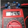
I have a VA meter - trouble is the settings are confusing -  not intuitive to non-electrical person. I am trying to test various Menards Power adaptors due to reports on the main forum that Menards buildings are frying from one or more of them. I have all 3 models of the adaptors - one of which is no longer made. I am in the process of setting my Menards buildings on my layout and would like to see what's going on before sending juice to them.

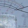
One Power adaptor (model 4006) says it's supposed to put out 4.5 volts and 2000 mamps. My meter has 4 different dial settings for DCV - 2.5, 10, 50, and 250. To start, I set dial to 50  ~ and needle moved; then set dial to 10 - needle moved further; and then to 2.5 and needle moved even further. The meter has 3 different scale ranges for AC & DC volts - see if you can see what I mean in picture (middle range of meter is AC&DC - readings in black font) - the first scale starts at 0, then 1, 2, 3, 4, and 5. 2nd scale starts at 0, 2, 4, 6, 8, and 10. 3rd scale starts at 0, 5, 10, 15, 20, 25. My question is what dial setting corresponds to what graph range on meter, and which dial setting should I set to? And, what do the dial settings reference ~ DCVolts?

As far as measuring mamps - this is even more confusing - meter has dial settings for 0.05, 25, and 250, and when I tested the adaptor for each dial setting the needle pegged each time - guessing that's because adaptor output is greater than any of those dial settings; if accurate then I am guessing my meter cannot measure in the 2000 mamp range?

Thanks for any help.


Attachments

Images (1)
  • HPIM0278
Last edited by Paul Kallus
Original Post

Replies sorted oldest to newest

You use the scale that has a number that is the same as the number on the switch setting...disregarding the decimal point.

You only measure amps by selecting the proper mamp scale which is greater than what you expect from your circuit. You insert the meter leads between the source (transformer) and the load (resistor, bulb, what have you). The other lead of the transformer goes directly to the other side of the load. Then you will read the current (mamps) that the load draws (not the limit of the transformer which is what you refer to...2000mamp). Keep in mind that if your load is a short or draws more current than the meter is capable of measuring, you will usually blow a fuse inside the meter. I am guessing (since your picture has too much glare to read the dials) that your meter has a limit of 250 mamp.

Dale, I don't follow you. The settings on the meter for DCV are 2.5, 10, 50, and 250. Does this correspond to upper voltage readings for that setting?

Stan, I set the dial to 10 and measured the adaptor output - on the scale you circled the needle stopped about 8.5 volts. If that's the right line to read the voltage and its accurate, then the adaptors from Menards are indeed putting out more voltage then they specify - which may be the reason peoples buildings are frying (buildings need only 4.5 volts). Note, reading the scale beneath the one you circled reads 4.5 volts with dial at 10. When I set the dial to 50 and read the scale above the one you circled I get just under 5 volts.

Why is the meter ambiguous on which line of numbers to read as compared to dial setting?

Thanks everyone, still would like to know what I am doing.

Last edited by Paul Kallus
Paul Kallus posted:
...
Note, reading the scale beneath the one you circled reads 4.5 volts with dial at 10. When I set the dial to 50 and read the scale above the one you circled I get just under 5 volts.

Why is the meter ambiguous on which line of numbers to read as compared to dial setting?

Thanks everyone, still would like to know what I am doing.

With the dial at 10, use the scale I circled...ignore the others.

With dial at 50, use the scale BELOW the one I circled (NOT the one above).  Since the one above indicates just under "5", the scale BELOW is indicating just under "1". With the dial set to 50, you interpret the scale BELOW as 0,10,20,30,40,50...rather than 0,1,2,3,4,5 as printed on the face.   Very confusing but that's the way it is!

Not that anyone needs more clutter around the train room, but at your convenience why not get one of those "free" with coupon Harbor Freight digital meters?  I stalked your profile and it appears there are HF stores in PA.  

Paul Kallus posted:

Dale, I don't follow you. The settings on the meter for DCV are 2.5, 10, 50, and 250. Does this correspond to upper voltage readings for that setting?

Stan, I set the dial to 10 and measured the adaptor output - on the scale you circled the needle stopped about 8.5 volts. If that's the right line to read the voltage and its accurate, then the adaptors from Menards are indeed putting out more voltage then they specify - which may be the reason peoples buildings are frying (buildings need only 4.5 volts). Note, reading the scale beneath the one you circled reads 4.5 volts with dial at 10. When I set the dial to 50 and read the scale above the one you circled I get just under 5 volts.

Why is the meter ambiguous on which line of numbers to read as compared to dial setting?

Thanks everyone, still would like to know what I am doing.

You might put your meter on 10 vdc setting and read 3 AA cells in series. Just to check the accuracy of the meter. It should read 4.5 to 5 on the 10 scale.

Paul Kallus posted:
... I set the dial to 10 and measured the adaptor output - on the scale you circled the needle stopped about 8.5 volts. If that's the right line to read the voltage and its accurate, then the adaptors from Menards are indeed putting out more voltage then they specify...

If you are reading the output with an open circuit - no load - then that is about right what you are reading. For an accurate measure, the load has to be close to the rated output(2 amps is the specification you give above in your OP). Any (expected) load will get it closer to 4.5 volts quite quickly.

Stan, with the dial set to 50 the meter reads just 1 volt (from the bottom row of the scale you cited).

Rob - I don't think I can measure with load since the meter probes have to go in the plug and on the outside to make a circuit. Are you thinking 8.5 volts would be normal in the unloaded state? Trying to figure out why some people's Menards buildings are frying.

Thanks, everyone, I'll see if I can find a digital meter.

Paul Kallus posted:

Stan, with the dial set to 50 the meter reads just 1 volt (from the bottom row of the scale you cited).

Rob - I don't think I can measure with load since the meter probes have to go in the plug and on the outside to make a circuit. Are you thinking 8.5 volts would be normal in the unloaded state? Trying to figure out why some people's Menards buildings are frying.

Thanks, everyone, I'll see if I can find a digital meter.

Right.  You should be reading just under 1 on the bottom scale.  That means just under 10 Volts which is what you got using the 0-10V dial setting and middle scale.  Again, it's confusing for sure, but you need to mentally multiply the indicated reading on the bottom scale by 10 when using the 50V DC dial setting.

As I understand it you have the 3-outlet Menards adapter.  I think what Rob is asking is to measure the voltage in one of the unused plugs.  So go ahead and plug in one building.  Now measure the voltage at one of the two unused plugs.


Okay, Stan, I was able to test the load - I plugged in 2 buildings and tested the unused plug: With dial set to 10 I measured around 7 volts; with dial set to 50 I measured just under 1 volt. If I understand you right, I need to multiply by 10 when using the "50 dial setting" ~ so that would put it around 7-9 volts. And, the 10 scale is one for one, so if right then that means the adaptor is indeed putting out more voltage then the 4.5 volts the buildings require. Could this be the reason why the guy on the main forum (he goes by Panther) buildings are frying?

fwiw, I noticed when plugging the adaptors back into the buildings the building lights go on for a second, then off, this with the household plug not plugged in. Does this mean anything, a capacitor in the adaptor maybe?

I have an old HO DC transformer - that I could potentially use for these buildings - it goes up 18 volts DC with lever, I believe. I also have to contact Menards as I have 4 of their adaptors.


Last edited by Paul Kallus

I think you now have your arms around the "multiply the lower scale by 10" thing for the 50 V dial setting!

To summarize your measurements, the no-load adapter voltage is 8.5V DC.  Loaded by 2 buildings it drops to about 7V DC.  That seems a bit high to me for a 4.5V DC adapter where "full" load is 3 buildings.  As to whether or not these voltages damage Menards buildings is something I can't answer.  From what I've read, Menards does not specify operating voltage and current for various buildings...essentially saying to just use their 4.5V DC adapter.

Yes, that brief flash when you plug a disconnected (but recently powered) adapter back into a building is a capacitor inside the adapter discharging its stored energy.

For 2.5 dial setting, use upper scale (marked 0,5,10,15,20,25) and divide the reading by 10. 

For 250 dial setting, use upper scale and multiply the reading by 10. 

The idea is that the adjustment factor makes the full-scale (needle all the way over) reading the same value as the dial setting.

As for a digital meter. Presumably you've built your layout etc. and have been running trains fine without one so obviously it's not a must-have.

In fact, if you just want to mess around with one, I will send you a new Harbor Freight digital meter (the kind you cab get Free with coupon).  Battery included!   I'll even test it first and the postage is on me!  I have a bunch of them. 

ogr hf meter measuring ps1 smoke motor - Copy

I don't see your email in your profile so email me a shipping address to this temporary email address which I'll disable after I hear from you one way or the other:

...

Attachments

Images (1)
  • ogr hf meter measuring ps1 smoke motor - Copy
Last edited by stan2004

That's real nice of you, Stan...my friend's brother said he has one extra from Harbor Freight and will give it to me, so no need to spend postage, thanks for your offer.

Its funny, I found the instructions for the Sperry analog meter I have, and there's nothing useful in it.

I am wondering if I splice the main adaptor power cable and add 10-15 feet of wire - would that reduce the voltage? Probably a formula? I estimate the adaptor has 20 gauge wire, I could use a long run of that or even 18 gauge. I have about 8 Menards buildings that I am just now getting on my layout - just the past year I finished the track work.

Got your email.  I'll answer your question here about the dial setting of the HF meter since we may need to refer to it again.
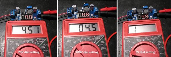
HF digital meter settings

So here's the HF meter measuring the DC output of an eBay voltage regulator module that has been set to 4.5V.  In other threads, I suggest these modules as an inexpensive way to generate regulated DC voltage for Menards and Lemax buildings, Miller signs, etc.  In this case the module even has its own digital meter showing it has been set to 4.5V DC.

Anyway, with the dial setting at 20V (left) the HF meter reads 4.51.  This would indeed be the setting to use for the Menards adapter issue at hand.  If you go to the 200V (middle) setting, note how the decimal point automatically moves for you...no need to mentally adjust the factor.  But note how you lose resolution in the measurement.  This is why you want to use the lowest dial setting that still covers the range of voltages you expect to measure.  This loss of resolution is like your analog meter's needle barely moving if the setting is too large; you can see the needle move but difficult to resolve the value. 

If you go to the 2V (right) setting, the 4.5V overwhelms the meter.  In this case the meter display just shows a "1".  Other meters might display "OF" (OverFlow), or flash, or whatever.  On an analog meter this is where the needle is pinned over to the right side.

More expensive meters have so-called "auto-ranging" capability which automatically chooses the dial setting to maximize the resolution.

As to the wire issue, yes, it's all about formulas.  Look it up in any wire-table and 20 gauge wire has a resistance of about 1 Ohm for 100 feet.  If you are running a 15 ft cable pair or 30 ft of wire that is a resistance of 0.3 Ohms.  Then you use the Ohm's Law which tells you how much Voltage you lose.  Voltage = Current x Resistance.  You need to know the Current (Amps) which, as I've previously lamented, Menards does not seem to publish.  But a reasonable guess is to note that their 1-building adapter is rated at 500mA (or 0.5 Amps) and their 3-building adapter is rated at 2000mA (or 2 Amps).  So let's just go with 0.5 Amps per building.  That means your 15 ft cable will drop/lower the voltage by 0.5 Amps x 0.3 Ohms = 0.15 Volts.  So if the voltage "started" at 4.5V DC, introducing the extra 15 ft of 20 gauge wire means the building only get 4.35 Volts.  My opinion is you shouldn't see a material difference in brightness or behavior for that small a change. 

Note that if you do make such an extension cable you will only see that voltage drop when the current is flowing into the building.  If you measure the voltage at the extended plug (not plugged into the building) you will measure the original voltage.  In other words the current is 0 Amps so the voltage drop from the 0.3 Ohm extension cable is 0 Amps x 0.3 Ohms = 0 Volts.

Finally, the HF meter also has the ability to measure DC current.   I believe we concluded that your existing analog meter only goes up to 250mA (0.25 Amps) which presumably is not enough to measure the building current.  When you get the meter, we can get into the specifics of how to measure building current with the HF meter if you are so inclined.

Attachments

Images (1)
  • HF digital meter settings
Last edited by stan2004

Chuck, nice setup! 

Do you have an eBay (low-cost) source for the black jumper strip shown in your photo - I assume it's 9.5mm / 3/8" centers and it was cut-to-6 positions?

Why the electrolytic capacitor on the right edge of photo which is presumably between the + and - bus on the terminal strip?

And the $64,000 question...why is it set to 4.67V DC? 

Last edited by stan2004

Add Reply

Post

OGR Publishing, Inc., 1310 Eastside Centre Ct, Suite 6, Mountain Home, AR 72653
800-980-OGRR (6477)
www.ogaugerr.com

×
×
×
×
Link copied to your clipboard.
×
×