is it at all possible to run two trains on the same track using a ZW transformer? With no problems? Been reading old posts with lots of things I don’t understand! I have the 3 rail track n switchers, but not sure if I would need anything else! 

Feedback would be appreciated! 

Thanks, Jibbs the newbie.

Original Post

Replies sorted oldest to newest

Can do with 2 different LionChief Plus engines in remote mode using 2 remotes or the universal remote.

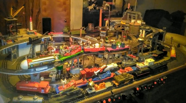
Conventionally, can do using block wiring and fiber pins and having properly phased transformers. However, it makes me a little anxious to run 2 trains on the same main line track , so I opted for 2 interconnected and independently powered main lines. 20181127_081454

Fiber pins are in the usual places in these 022 switches plus there are fiber pins where the switches meet between the outer loop (main line on top) and the inner loop (main line on bottom). I use an MTH Z4000 transformer in which the left throttle controls the inner loop and the right throttle controls the outer loop. 

Trains have plenty of power and run smoothly between the inner and outer loop. Set the throttles so the train goes at approximately the same speed between the inner and outer loops.

I also use fiber pins, Atlas switch controls and a ZW transformer to independently power 8 sidings on my layout. This enables me to park a locomotives on each siding while running other engines on my 2 main lines. ZW must be properly phased with the MTH Z4000.

This arrangement enables me to run 2 independently powered trains (one train on each loop) or one train from one loop to the other loop, while other locomotives are parked on the sidings. Arnold


Attachments

Images (1)
  • 20181127_081454

What ROMILLER49 says if you are into that.

I ran two trains traditionally on a multi return looped layout on three tables.  one track power right side ZW  one electric ( GG1 or EP 5) from over head  (pantograph pick up) power left side ZW.

it was a challenge to keep an eye on both engines, but a lot of fun.  I did it on the last layout, I may do it again on the rebuild. It was really straight forward operation. Without complex issues.  


Karl Reichenbach posted:

I run 4 trains on the same track using conventional control with power blocks and 5 postwar ZW's.  Of course the loop is over 900' long.  Engines are Williams.  Right now for my Christmas Open House 3 of the trains have 2 lashed up Williams engines.  The biggest problem is watching all 4.

"Of course the loop is over 900' long." Now that is just plain cheating!

Jibbs posted:

Thank you all so much for your knowledge n input!when I get done I will post pics or videos of it! You guys are great to help me out! 

The help may have been even more precise, but you left possiblities wide open by not being more specific on which type of train (new or old, with pantigraph or without (lol.. the GG-1/electrics can do that though), etc etc)

Every one of Gramps big loops was split into at least two blocks, each half on 1 ZW handle.

  At other times, 4 blocks on two throttles, the last block of each handle also had a relay with a resitor. Block 1b being occupied caused the 1a relay to insert the resitor, slowing 1a greatly until 1b cleared.  Then 2a slowed 1b till 2a cleared, etc, etc.  ....a fast train got slowed automatically..   You could reduce the amount of low volt insertions as much as you desire, but each tends to lead to fluid operation imo. (still takes "balancing" of throttles. To ensure 100% anti colision, each slowable block must also contain a " temporary dead section" in case the amount slowed doesn't actually slow enough for the first train to clear its block in time.

Today I would use diodes in a voltage drop circuit, not resistors.

Despite what folks generally call them, Lionel included, a "turnout" is the correct track term, "switches" are slang. A switch is actually an electrical part, like a "toggle switch", so most times "turnout" is the better choice anyhow imo. (catching this now, before bad habit forms puts you in the wise )

Switches also require some special consideration in placement.

My comments were based on 2 trains on one loop. Two loops connected by turnouts, one loop on each handle would require only slightly different placement of isolation pins.  (you actually have four throttles, but I dont count the little ones usually, but they can be used)

Leroof posted:

What ROMILLER49 says if you are into that.

I ran two trains traditionally on a multi return looped layout on three tables.  one track power right side ZW  one electric ( GG1 or EP 5) from over head  (pantograph pick up) power left side ZW.

it was a challenge to keep an eye on both engines, but a lot of fun.  I did it on the last layout, I may do it again on the rebuild. It was really straight forward operation. Without complex issues.  


Leroof, your reply reminds me that I have found it to be fun to run a train and the Postwar #60 trolley on the same track.

The trolley saunters along and can be positioned to avoid colliding with the train, but you still need to keep your wits about you.

Adriatic posted:
Jibbs posted:

Thank you all so much for your knowledge n input!when I get done I will post pics or videos of it! You guys are great to help me out! 

The help may have been even more precise, but you left possiblities wide open by not being more specific on which type of train (new or old, with pantigraph or without (lol.. the GG-1/electrics can do that though), etc etc)

Every one of Gramps big loops was split into at least two blocks, each half on 1 ZW handle.

  At other times, 4 blocks on two throttles, the last block of each handle also had a relay with a resitor. Block 1b being occupied caused the 1a relay to insert the resitor, slowing 1a greatly until 1b cleared.  Then 2a slowed 1b till 2a cleared, etc, etc.  ....a fast train got slowed automatically..   You could reduce the amount of low volt insertions as much as you desire, but each tends to lead to fluid operation imo. (still takes "balancing" of throttles. To ensure 100% anti colision, each slowable block must also contain a " temporary dead section" in case the amount slowed doesn't actually slow enough for the first train to clear its block in time.

Great reply, Adriatic. Sounds like your grandfather built an advanced layout with numerous blocks properly wired with switch controls so multiple trains could be run without collisions.

I had a very good book that explained this block system. The title was something like Building an Advanced Layout. Unfortunately. I can't find it.  I may have lent it to someone over 10 years ago and never got it back.

A cautionary tale ...

A techno-wizard in our local train club wired multiple blocks for the club's large conventional layout, but some less technical members put a too-long freight train on the rails. When the length of that train "spilled over" two blocks, the block system got confused. Fortunately, that was easily "fixed" by shortening the trains so all would fit within the defined blocks. 

Later, the club abandoned the block system and installed TMCC control. As pointed out here, operators must PAY CLOSE ATTENTION to the location and movement of the trains and make appropriate speed/spacing adjustments with the club's CAB-1 controllers.  Sometimes, a rear-end collision occurred when an operator was momentarily distracted by "talking trains" with a visitor. Moral of the story:  train operation trumps visitor communication.

Mike Mottler     (ritrainguy)

I had/have dreams of a revival of that layout. I've been too physically limited to clean the space properly though. There are other issues too, like stairs. Down there, I don't think I'd do as much, nor as often.   Benchwork and wiring is still here though; about 15' or 18'x30' or 32'; I forget exactly but has been pulling "crap shelf" duty for decades.

I actually use a similar block set up on a ceiling shelf, but 2 loops that share a main along one wall. The main must be clear of train #1 before either loop releases train #2. My #1 actually as to fully clear the main before #2 triggers the anti derail at the mains entrance as the turnout's wiring at both ends of the main are tied together so the point dirrections are synced.

I had an assistant that saw "reds as greys". Never an accident but we began to using more number tags as a rule for him.

tncentrr posted:

I usually call it a "track switch" to distinguish it from an electrical switch. The word "turnout" is really the proper term, but you almost never see it used in Lionel's catalogs and other literature.

  I grew up calling them "switch tracks" myself, Gramps used that to differentiate from a electrical switch. Our retired Big Cheese Rich "set me straight one" day. Gramps tended to be pretty tight on prototypical use of terms; I still wonder if the use of "switch tracks" wasn't one of those regional mining or logging RR terms from somewhere up north or in Canada.

  I don't always adhere to using it, but appreciated the correction more than some might expect; at least I know what's actually used on the job now

I don't use command. I only have had a few that support it and or electric sounds. I grew up without the sound and to be honest, chuff got old and distracts my ears from the real mechanicals. The soothing rythm of the cyct tender is the one sound that doesn't distract or annoy me. I think it's because it so closely resembles the steady rythm of operating pumps off the post war oil towers; an ever present accessory on Gramps layouts.

So, two trains on one loop can be done, two loops connected and two trains also.... Command has lots of aspects to learn about. I'd encourage you to sample them, but not to act in haste. Be aware electronics are fickle too. The command game is more work, make sure your happy with the outcome of these types of efforts. I'm kinda lucky I'm "easily ammused" and don't feel I "need" it. (it kinda reminds me of work too. I didn't love my job THAT much )

Know your running style before you commit.( I'm a looper; my indoor campfire; I shoud have spent less effort on sidings and gone for double reversing loops.)

The options today are numerous.  It's often just easiest to read a highly detailed *"foolproof" explanation* or see a diagram of your intentions, needs, etc. and go from there. (It's still a little vague on loop count, etc.) ( * "to teach well, a teacher must assume the student knows nothing"....{Plato?})

  There is a Windows software program called SCARM(simple computer aided railway....manger? (I forget the M) ; google pulls it up. I think they still offer a free trial version (50pc limit).  (author Mixey posts here at times too)   Make a sketch with it. (include a jpg "screen shot" and the scarm file. Some folks don't run windows, but can still see and paint on a jpg., those with scarm can change things with the program and include a new scarm file for review.) 

  Making software layouts can be time killing fun as well as a prudent planner. Railroad Trak & Anyrail are two others, less learning curve, but scarm is worth the effort for the infinite axis, zoomable, 3d view.

 This sketch begot this layout, using the three old Lionel track types; O-27,O, Super O. (4.5x9)

android-asset-d81c15506dffe8152eec8216c52eb7b7524fa7dc78010196d3e71c489f75001d4.5x9leftbackground4.5x9spaceALL

Attachments

Images (3)
  • android-asset-d81c15506dffe8152eec8216c52eb7b7524fa7dc78010196d3e71c489f75001d
  • 4.5x9leftbackground
  • 4.5x9spaceALL
Jim R. posted:

In the real world of railroading, workers and trade publications and books call them switches, not turnouts. So Lionel catalogs and those of you who have called them switches for a lifetime are correct.

The term turnout was a concession to the fact that model railroads have many electrical switches.


You'll have to convince Rich of that considering he ran real ones for years.

I do like the argument though. Seems logical anyhow. 

It means I was righter longer than wronger, at the very least too   

Just to clairify, who conceded, us, them, or both?


I have now given considerable thought to the switch/turnout discussion.  I grew up reading Lionel catalogs and they were switches.  Lionel, the Bible of model railroading in the day, would not print anything that was not true.  Therefore they are switches.  AND, if I correctly remember my grade school and junior high days there was nothing electrical about the switches that were used on me.  Perhaps if there had been an electrical component they would have been more effective.

As this has been hashed about many times, I will add some information. The first image shows my notes regarding fibre pin placement. I did this setup with great success.
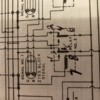
The second image is what continues to baffle me, the heavy black area on the outside rail makes no sense to me. It looks like two fibre pins in line but what is that heavy dark area between then? And what relays to use?
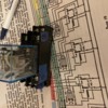
The third image is what I tried out this evening with success using a 153 block signal, and the pesky 153C contactor.

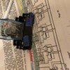
I would like to use a 153IR?? or I have a few MTH 40-1028 sensors fourth image. Cannot seem to get the wiring correct to substitute this for the 153C in relation to the third image.
Thoughts?

Attachments

Images (4)
  • F691BF6F-C287-427E-B660-F7CCB3160F78: First image
  • B596B51D-88F1-4ADF-9558-6DA4C0BF8BF5: Second image
  • D5DA0E44-023E-41D5-B38B-E5E11358B27E: Third image
  • B661B6E2-980A-41E1-9764-5E283A77FE87: Fourth image
@AlanOGauge posted:


The second image is what continues to baffle me, the heavy black area on the outside rail makes no sense to me. It looks like two fibre pins in line but what is that heavy dark area between then? And what relays to use?

That heavy black rail is an insulated rail section that triggers a relay coil. A possible relay suggestion would be along the lines of Sky Electronics 12VAC 10A DPDT relay.

@AlanOGauge posted:


The third image is what I tried out this evening with success using a 153 block signal, and the pesky 153C contactor.

I would like to use a 153IR?? or I have a few MTH 40-1028 sensors fourth image. Cannot seem to get the wiring correct to substitute this for the 153C in relation to the third image.

The 135C is essentially a SPDT device. Terminal 3 is the COMMON (not to be confused with common ground), Terminal 1 is Normally Closed (NC) and Terminal 2 is Normally Open (NO). The 153IR uses the parenthesized terminal notations and uses ACC PWR and ACC GND power supply in place of the singular COMMON.

Attachments

Images (1)
  • mceclip0

Alan,

These may help.  I took the liberty of colorizing them:

1.) Each of the dark green squares with a letter in them is a single piece of sectional track.  Some are 10" straights, some are O-31 curves or O-72 curves, etc.  Each colored rectangle represents a block.  In this drawing each block is made up of precisely 4 pieces of sectional track, although you could add more if you wish, if you do so carefully so as not to corrupt the circuit logic.  As @bmoran4 pointed out the heavy black line is an insulated rail on the piece of track it's drawn on.

5-Block Loop Signal and Control System_1a5_d

2.) Same here, but only one block is shown, instead of 5.  This approach needs more pieces of track per block because the 153C need the track above it to flex adequately, when the train crosses it, in order to switch its moving contact over to the N.O contact.  The orange squares are extra pieces of track inserted to get enough distance for the 153C to feel the track flex above it.  There is no heavy black line here because a 153C is used instead of an insulated rail to detect the train.

1-Block Signal and Control System_1a7d

I hope this helps.

Mike

Attachments

Images (2)
  • 5-Block Loop Signal and Control System_1a5_d
  • 1-Block Signal and Control System_1a7d
Last edited by Mellow Hudson Mike

I guess the insulated rail section that uses a relay is one that has one outside rail insulated from the metal tie and fibre pins in the center AND insulated outside rail. I do have some of these from Lionel although only the outside insulated rail has a fibre pin. Will check out the Sky relays.

Thanks for the colored drawings, it starts to put things into perspective. I will print them out at my office, make use of our color printer!!

Will post results as needed, it’s been a while since I brought out the trains I had as a child, had the engines gone over and can tweak and maintain the other cars/ accessories

Last edited by AlanOGauge

Jibbs,  If you are running a conventual layout with block signals, always important to try to match the length and speed of each of your trains.  Also you want the blocks to be longer than your longest train. This is to account for coasting to a stop. Also very important is good contact between your insolated rails.  This means good clean track and the wheels on all rolling stock and engines.  If I recall on one of the early "TM" videos, there was a guy who actually had all his wheels nickel plated to improve conductivity.  Even if you use relays, which is better, keeping everything clean is a good idea.

Dave   

@gene maag posted:

I have5 Lionel bump & go Trolleys and like to run 2 or more on the same track, but none of them run at the same speed...I tried resistors but it didn't work????

Gene,

I'm assuming that your trolleys are not command controlled, i.e. neither controlled by TMCC/Legacy nor PS2/PS3, but with a traditional transformer.

Where did you place the resistors in your attempt to equalize speeds?

Mike

Last edited by Mellow Hudson Mike
@Jibbs posted:

Well you guys are awesome! But I’m not good with electrical circuitry cause I’m color blind! I’ll have a friend help me with that! I just wanted two onsame track! Could they go in opposite directions?

Yes.

It is more of a childish fun activity but on a single track mainline I have short trains running conventionally  in opposite directions with them passing each other on long double ended siding.  I just cycle the F-N-R action to an opposite action in one or two trains depending on how many trains I run on the single track loop.

You can also set many trains to only run in one direction.

The loop runs around 200' of basement walls with passing sidings every 120  degrees.

Dallee also sells a package where this action can be automatic.

I don't think it should matter on the speed of a single unit like the trolleys as long as they all go in the same direction and probably need to have the slowest in the front with enough sections so that the fastest can coast to a stop on  a red signal from the block ahead.  If you are trying to do station stops, it probably will require more electronics for more precise stops, I think one per block. They acted like relays only electronic, no points to chatter.  Let us know how it goes?

Dave

First thanks to everybody for helping. I found and printed the article from CTT mentioned, it might be the way to go.
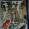
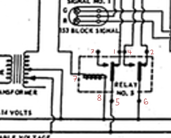
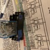
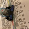
Got my relays in the mail today with mounts. See image of the top showing terminal placement and the other a copy from my old manual. I think I have marked the terminals on the copy correctly, would someone be kind enough to check please?


Attachments

Images (4)
  • 88A63F40-CBCF-42BA-84C9-EA8677510409
  • C29C60A5-9290-413D-968B-49EF1B0F2BBD
  • 1D4C4ACF-F04E-4881-8BA4-49848F6CA941
  • CD9F98BA-B098-4012-93FD-66AD8DED8139
Last edited by AlanOGauge

Looking at the schematic and your relay I believe this would be right:

Screenshot 2021-12-04 112014mu

It's important for correct operation to note that while terminal 5 is contacting terminal 1, at the same time, terminal 6 is contacting terminal 2 in the relay's normally closed state.

When energized, terminal 5 is connected to terminal 3 and terminal 6 is connected to terminal 4 as shown on the diagram on the top of the relay housing:

88A63F40-CBCF-42BA-84C9-EA8677510409

There's not enough information provided to determine which relay terminals correspond to which screw terminals on the socket base.  It may be best to confirm with a continuity check between each terminal socket slot and its corresponding screw terminal.

Attachments

Images (2)
  • Screenshot 2021-12-04 112014mu
  • 88A63F40-CBCF-42BA-84C9-EA8677510409

I have run 2 trains on the same track about 30 years ago. If you are adept at soldering, you place a heavy duty diode inline with the loco center rail pickup inside the engine. And on the other engine, solder a heavy duty diode but with diode in the opposite polarity. Then on my ZW transformer, I placed the same diode on the voltage output of the left throttle (A) and placed a 2nd diode on the right throttle (D).

You then have 2 separate throttle controls, with left controlling one engine and right throttle controlling the other engine. No wiring blocks to worry about. The engines will not get full power because they are running with the diodes, but you do get totally separate control for 2 engines running at their own speed. Also need to turn off e- unit as I recall.

Carl J

Hi Bob,

Agree completely that modern wireless Command Control like Lionel introduced makes it very easy to get 2 trains ( and more!) on the same track working at different speeds without interfering with other locos/ speed direction or need of all the wiring blocks and relays. That is why I felt it was the “Holy Grail” to see Wireless command control come out.

Carl J

@Carl J posted:

modern wireless Command Control like Lionel introduced makes it very easy to get 2 trains ( and more!) on the same track working at different speeds without interfering with other locos/ speed direction or need of all the wiring blocks and relays.

What is being done here with relays and whatnot is so much more than what Command Control can offer alone.

Command Control does not have this automatic signal control nor automatically keeps trains from colliding. Once this setup is up and running, no user input is required.

Last edited by bmoran4
@Carl J posted:

I have run 2 trains on the same track about 30 years ago. If you are adept at soldering, you place a heavy duty diode inline with the loco center rail pickup inside the engine. And on the other engine, solder a heavy duty diode but with diode in the opposite polarity. Then on my ZW transformer, I placed the same diode on the voltage output of the left throttle (A) and placed a 2nd diode on the right throttle (D).

You then have 2 separate throttle controls, with left controlling one engine and right throttle controlling the other engine. No wiring blocks to worry about. The engines will not get full power because they are running with the diodes, but you do get totally separate control for 2 engines running at their own speed. Also need to turn off e- unit as I recall.

Carl J

Can you run other trains without any problems and does the transformer diode affect the speed of other engines?

Hi Gene,

Your question on running other trains without diodes is an interesting one. Once you have added the diodes to both ZW throttles, trying to run any engines that do not have the diode installed, will mean that the unconverted engines put on the track will operate from both A and D throttles on the ZW. The unconverted engines without diodes do not run “separate” as will the engines with diodes installed. So you no longer have totally 2 separate engines running from 2 separate ZW throttles anymore. The ZW throttles with installed diodes will impact the top speed of both the engines with and without diodes. The speed will be slower overall with diodes installed on the ZW and engine. The system is now work with “pulsed DC” for the positive or negative part of the full AC wave form.
As I recall, the speed of the converted engines probably running 1/2 speed which was still plenty of power to go up my old layout grades.

Carl J

I have decided to go with Bob Walkers idea from CTT October 2007. It’s very straight to the point, not complicated, the necessary items will arrive next week.
This does not mean I am giving up on relay operations, will set up a large separate test oval and figure out how it’s done.
Hopefully will find the time to drive to Chantilly, never been to that show. Don’t get up to the area much any more for one simple reason, traffic. I remember as a child watching the trains run parallel to Washington Blvd in Arlington during the 60’s, later on when 66 opened up it all went down the sewer.

Parts arrived yesterday, I have attached a color copy of the article. I should have all the colors marked correctly, the lighter color appears to be grey, white is white, black should be the darker color and red/green appear to be tied in together.

Using a ZW transformer and looking at the drawing since it shows Red/Green and Black to 12V AC or DC I am confused  as to placement of Blue, Red/Green and Black. Blue could go to A or D (throttles on transformer) Red/Green could go to B or C and Black (common) would go to U   am I correct?

It might be easier to have a separate 12V AC power supply for Red/Green, Blue appears to be supplying power to all relays and track power/left/right section.

What do you think? I think I have it correct. Used to working with automobile schematics, parts manuals, 

Attachments

Add Reply

Post

OGR Publishing, Inc., 1310 Eastside Centre Ct, Suite 6, Mountain Home, AR 72653
800-980-OGRR (6477)
www.ogaugerr.com

×
×
×
×
Link copied to your clipboard.
×
×