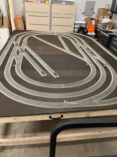
Had time this weekend to work on the layout.   Track is pretty much finished.   I’ll add some additional sidings but it’s not a priority.  Plus, I don’t think I have much room to add any more.   Still have to return and swap the turn out that won’t program.

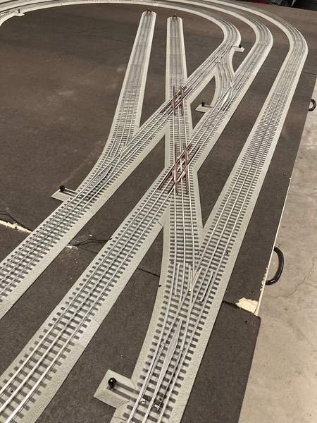
Didn’t think I would be able to have an entrance and exit crossover between the 2nd and 3rd loops but I was able to tuck the extra turnouts near the crossings.  

6F39092A-8AAE-4C80-B8CE-D39E9DE70A9F

Really like how the double crossover section came out.  The Fastrack geometry came together nicely.   This area is a scene that will carry over to the future layout where I’ll have a short line crossing a double mainline, though there will be additional turnouts to accommodate interchange switching.

If I was adding detail to this layout, the parallel sidings would be perfect for an engine maintenance facility.  

A12A4CB5-C65C-47D0-A341-FD182210C8E8


Next I need to double check the wiring and program the new turnouts.   Hopefully I can do a few test runs tomorrow.  

Attachments

Images (2)
  • 6F39092A-8AAE-4C80-B8CE-D39E9DE70A9F
  • A12A4CB5-C65C-47D0-A341-FD182210C8E8
Last edited by VJandP
@VJandP posted:

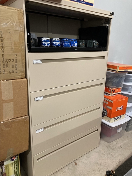
Found an inexpensive, sturdy storage option that required little effort to set up.  

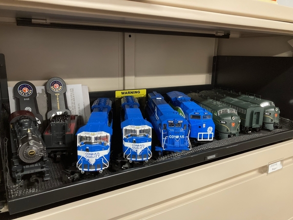
A lateral filing cabinet cost me $60 from Facebook Marketplace.  A few more bucks for rubber liners for the drawers and I have someplace to store much of my rolling stock and engines.  This should keep them dust free, too.  And now everything is easily accessible.  Ideally something that has more shallow drawers and a few extra drawers would have been sweet but I can’t argue when the universe drops an opportunity in front of you  

He had a few of these cabinets and I think I’m going to grab another one since this one is working so well.  

7B6CBA03-925B-4D64-9CA7-119369F9B9288ECC0F4E-B44F-4400-AC04-A46270FAED369E8E925C-D9E4-47F8-8750-7F23EB6E2CD9

Vin

Welcome to the Forum.....you have done a lot in the past 2 months.....I love your storage idea and look forward to your progress.

Peter

Today was a little frustrating.  Was hoping to have some trains running but electrical issues derailed those plans - pun intended.

Issue: Track power is erratic.  Engines will stall and the lanterns on the turnouts will go out.    

I think part of the issue are the turnout’s sensitivity to how level they’re laying which I’ve already noticed.   But now that I have the track Tetris’d together, the slight bows and humps are causing issues.   If I press down the road bed, that section will be ok.  I need to order more screws to fasten down a larger part of the layout.  But before screwing everything down ….

After doing some searching, I might have a power issue - too much load per channel.   The outer loop has 5 turnouts on track power.  The 2nd and 3rd loops each have 4. The 3rd loop also has 2 lighted bumpers. It might be in order to run a bus around the layout to distribute the power better.   I’m going to post in the electrical forum with some questions.

The other thing is that I noticed the ZW-L was humming.   Not sure if that has anything to do with anything or if it was there before, but it was really noticeable today. I swear sections of the track sounded like they were humming too but that could’ve been sound from a different source that I couldn’t localize.

Last edited by VJandP
@VJandP posted:

Today was a little frustrating.  Was hoping to have some trains running but electrical issues derailed those plans - pun intended.

Issue: Track power is erratic.  Engines will stall and the lanterns on the turnouts will go out.    

I think part of the issue are the turnout’s sensitivity to how level they’re laying which I’ve already noticed.   But now that I have the track Tetris’d together, the slight bows and humps are causing issues.   If I press down the road bed, that section will be ok.  I need to order more screws to fasten down a larger part of the layout.  But before screwing everything down ….

After doing some searching, I might have a power issue - too much load per channel.   The outer loop has 5 turnouts on track power.  The 2nd and 3rd loops each have 4. The 3rd loop also has 2 lighted bumpers. It might be in order to run a bus around the layout to distribute the power better.   I’m going to post in the electrical forum with some questions.

Vin, I empathize with your power issues.  Been there done that with FasTrack.  My first two recommendations would be to wire the switches directly with Aux Power and Ground.  The Second, sounds like you're already thinking this, add track feeders (hot and common) every 6-10 track pieces.

If you post on the electrical forum, I would suggest including your latest SCARM plan.

@SteveH posted:

Vin, I empathize with your power issues.  Been there done that with FasTrack.  My first two recommendations would be to wire the switches directly with Aux Power and Ground.  The Second, sounds like you're already thinking this, add track feeders (hot and common) every 6-10 track pieces.

If you post on the electrical forum, I would suggest including your latest SCARM plan.

Using a separate power source for the switches or just wiring them direct off the track power bus? Not an issue for me at the moment but thinking about the future when a dozen switches are in play.

There are 2 main reasons I prefer to have FasTrack switches wired on their own separate bus, powered at about 14 - 16 volts AC.  This allows a different track voltage (good for conventional and command).  The other reason for this electrical separation is that in addition to having TVS diodes installed in appropriate locations around the layout, keeping switches on a different bus helps protect the electronics inside them from the transient voltage spikes on the track power circuit caused by a derailment.

Last edited by SteveH

If anyone has links to a thread or a good guide on how to do this, it would be appreciated. All the searching I’m doing, there’s always opinions on what the best wway to do it is.

I am going to use one of the accessory channels on the ZW-L.  I’ll run that to a bus and from there to the turnouts. What gauge wire would be best to do this with?   Also, one video I watched said to only run a hot lead to the turnouts and use common ground through the track? Or do I need to do a hot and ground to eat turnout?

Last edited by VJandP
@GregK posted:

Using a separate power source for the switches or just wiring them direct off the track power bus? Not an issue for me at the moment but thinking about the future when a dozen switches are in play.

@GregK Like you, I was fine while there were only 5 turnouts.  Now I have 13 and things are getting a bit wonky.  Power delivery isn’t consistent.    It’s not just the turnouts, the overall performance of the layout decreased dramatically as I expanded it.  

@VJandP posted:

@GregK Like you, I was fine while there were only 5 turnouts.  Now I have 13 and things are getting a bit wonky.  Power delivery isn’t consistent.    It’s not just the turnouts, the overall performance of the layout decreased dramatically as I expanded it.  

My little 4x8 layout with 2 loops seems fine with only one track drop on each loop, but I’m still doing two on each loop just to be safe. Like the others said, just need feeders every so often. People also bend the center FasTrack pins to encourage better contact but you have a ton of track… I would think on a layout your size, 3-4 drops per loop would give you good coverage. But I’m no expert, just basing that on with the pros post here. 😊

@GregK posted:

My little 4x8 layout with 2 loops seems fine with only one track drop on each loop, but I’m still doing two on each loop just to be safe. Like the others said, just need feeders every so often. People also bend the center FasTrack pins to encourage better contact but you have a ton of track… I would think on a layout your size, 3-4 drops per loop would give you good coverage. But I’m no expert, just basing that on with the pros post here. 😊

Good call out on bending the pins. Every little bit helps, right?   I had read that somewhere also. I definitely need more drops to the track for starters.  How are you connecting wires to the track? Using the built-in terminals? Soldiering?

I just realized, the way my track plan is laid out, most of the straight sections on the loops are taken up by turnouts and crossovers. I don’t have many 10” straight sections with terminals to connect to. I’m gonna have to figure out a way how to attach power to curved sections, 5” straights or something else…

Dedicated turnout power bus wires' gauge will depend on the number of turnouts connected and the bus length.  If only a few switches, 18-16 gauge would be fine on a small layout with 18 gauge feeders.  For a larger layout I'd suggest 14 gauge bus wires with 18 gauge feeders.  Switch grounds should be tied to track common at the main distribution point near the transformer(s, and phased if more than one transformer).

Feeder wiring to the turnouts would be: Hot to Aux power terminal, Common to the power ground terminal.

Track Power can be connected to any piece of track by soldering to the rail tabs under the roadbed.  Track pieces with spade connection tabs include: Full curves, 10" and 1-3/8" straights.

Thanks, guys.  I didn’t realize the curved sections had terminals under them.   I think I’ll run a feeder to each “corner” of each loop - 4 drops per loop.  Maybe 2 more on the longer sides of the outermost loop.  I picked up the .001 spade connectors or whatever that size is, so I can make feeder wires w/ connectors.   For the future layout, I think I need to pick up some soldering skills.  

@SteveH Thanks for the detailed info. Hate to sound like a total newb, but can you break it down a little more for me?    After reading your input, here’s what I was going to do.  Let me know if I misinterpreted or there’s a better way …

For the turnouts, from an accessory channel [C] on the ZW-L, I was going to set the channel to 14 volts.   Since everything is being run off of the same transformer, I don’t think there will be any issues with phasing.   I’ll feed a hot wire and a ground to 2 separate bus bars.   Each turnout will be tapped into a hot and ground respectively on each bus bars.

When you mentioned “Switch grounds should be tied to track common at the main distribution point near the transformer…”, I wasn’t sure what you meant by the main distribution point.  Will the bus bars do the same thing?

@VJandP posted:
..“Switch grounds should be tied to track common at the main distribution point near the transformer…”, I wasn’t sure what you meant by the main distribution point.  Will the bus bars do the same thing?

Bus wires and bus bars are essentially the same thing electrically; a means of connecting more than one electrical load via a central current carrying apparatus (bus) to the power source.  In the case of grounds, they should all be tied together somewhere, typically at or near the transformer.

If you're planning for DCS then all power should be tied back to a central distribution hub that is fed by the transformer.  The latter is known as star wiring.  For more on that I would recommend reading the DCS Companion.

@VJandP posted:

@GregK As of right now, I do not have blocks though that is in the future. Do I need isolated blocks to run feeder wires around the loop?   Or is it OK to have multiple hot and grounds on the same continuous loop of track?

Isolated blocks are optional and depend on whether you'll be running DCS and/or conventional and other factors.  For what you're doing right now with your test track you could skip them for the time being.

Multiple feeders on the same block will help reduce the voltage drops you're experiencing.  But if you'll be running MTH DCS locomotives, there are limitations to the way feeders can be connected to track blocks without interfering with the DCS signal.

Last edited by SteveH

Invest in some good needle nose pliers. Helpful when slipping the spade connectors onto the track tabs. They make a really snug fit and are a good alternative to soldering but a bit of a pain to slide on. The little spade connectors work well tho. Slide a wire in and crimp it. Forms a good bond and I imagine it wouldn’t come apart under normal circumstances. I put a few together tonight from the ones I posted from eBay.

Add Reply

Post
The Track Planning and Layout Design Forum is sponsored by

AN OGR FORUM CHARTER SPONSOR

OGR Publishing, Inc., 1310 Eastside Centre Ct, Suite 6, Mountain Home, AR 72653
800-980-OGRR (6477)
www.ogaugerr.com

×
×
×
×
Link copied to your clipboard.
×
×