


quote:Originally posted by prrhorseshoecurve:quote:OK, dumb question but... I have never figured out... just what does a non derail board actually do?
Simply put the board:protects the switch motor from burning out due to holding the button down too long interfaces the Atlas O signal system to the swich. as designed it will act as a non derailing circuit just like a Lionel switch also can activate TWO switch motors simultaneously as in a crossover or a passing siding.
Once the non-derail function is in place it can be used for power routing in trouble areas where switch dead spots occur.
http://www.amhobbiesonline.com...virtuemart&Itemid=62
quote:Originally posted by Austin Bill:
Hi Guys, I just finished successfully installing my first #57 switch controller. Works great. Leds are bright and the lever and pushbutton action seem much more precise than with the old #56's.
If you use the #6924 Circuit boards to control your Atlas O switches and provide other functions such as non-derailing and dwarf signal activation -- as I do -- then the #57 wiring is different.
Below is the wiring diagram Steve Horvath sent me on how to do it. Please pardon the photo quality as I'm busy wiring new #57's!!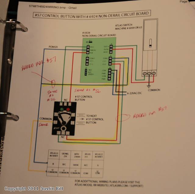
Would be nice if Atlas had a instruction sheet area on their web where we could read what something does and hookup. I went to Atlas O and HO sites and learned all about the great releases and found the 57 controller, but no area for instructions, closeups, hookups.
Come on Atlas you can do better than this.
Atlas O does have technical info on their website. It's just in an unusual place. Clicking on "new products" takes you to a page with a box on the right side containing Atlas O Product Links. Then make a selection -- in this case Manuals & Instructions.
There you will find lots of instructions and diagrams.
However the #57 switch controller is not yet there. Guess the product release guys beat the tech writer guys and website mgt guys to the punch!
The diagram Steve Horvath sent me clearly shows that the documentation for using the #57 with the Universal Control Board has been prepared and is ready to be added to the website. Of course the #57 has many other applications which need diagrams.
Austin Bill
Here is a link to existing information.
Tech information
Another link to parts.
Parts
Another parts link. This is a very difficult list to use.
Original Parts list
Tech information
Another link to parts.
Parts
Another parts link. This is a very difficult list to use.
Original Parts list
Thanks Austin Bill, You are right that is an unusual place to put needed information. Thanks Mike for the three URLs to parts lists will fill the URLs for reference.
I now have six of the #57's installed for my mainline #7.5 Atlas O switches using the non-derailing board features for throwing the switch, and for dwarf signals and with non-derailing installed.
They're a huge improvement over the #56's. More precise. Good action. LED's have a good intensity. Can see the status of all 6 switches from anywhere in my 32 X 17 trainroom.
Austin Bill
They're a huge improvement over the #56's. More precise. Good action. LED's have a good intensity. Can see the status of all 6 switches from anywhere in my 32 X 17 trainroom.
Austin Bill
Added instructions to mod controller to work with Ross turnouts
Sam,
Suggest you consider contacting Steve Horvath at Atlas O with your idea. I'm pretty sure he's the guy who designed the #57. And if not he'll know who did design it.
It would seem to be in Atlas O's best interests to have the #57 work with other mainstream products like RCS if the solution is cost effective in our brutal economy.
Austin Bill
YEs HE did, Including my suggestion to Print the CTC like lettering/design on the controller!quote:Sam,
Suggest you consider contacting Steve Horvath at Atlas O with your idea. I'm pretty sure he's the guy who designed the #57.
Seems to me that if you have to buy a non-derailer circuit board + the switch controller for each switch, the deal just got way pricier.
NOT necessarily. the circuit board can connect multiple switches if needed so one doesn't need a circuit board for EVERY switch. thwe circuit board will depend on your application on your railroad.quote:Seems to me that if you have to buy a non-derailer circuit board + the switch controller for each switch, the deal just got way pricier.
You don't HAVE to buy the new #57 switch controller. You can just use the #56 switch controller that's packaged with the switch.
You don't HAVE to buy the mult-purpose #6924 Non-derail circuit board either. Just wire the switches according to the diagram in the switch package.
Besides, non-derail circuit board is a mis-nomer. This board is capable of MUCH MORE. Probably should be named Multi-function Circuit Board.
I would like to complement Atlas O on bringing out these two products which FOR ME have enhanced my model railroading experience. Well worth the money.
And with Atlas O everything works together and all are very reliable. This is NOT the case with a certain switch machine/switch combo offered by another company. My train buddies are having nothing but big problems with them.
Austin Bill
Looks like Atlas O posted a few diagrams under the Manuals heading. They put them up on the #57 page as well.
http://www.atlaso.com/manuals.htm
http://www.atlaso.com/manuals.htm
quote:Originally posted by CNJ77:
Looks like Atlas O posted a few diagrams under the Manuals heading. They put them up on the #57 page as well.
http://www.atlaso.com/manuals.htm
However the #57 page suggest looking at the atlasrr/support page but it does not exists far as I can tell.
As far as I can tell, Atlas O still hasn't posted the wiring diagram for using the #57 with the #6924 non-derailing board. Am I missing it on the Atlas O website?
Austin Bill
Austin Bill
quote:Originally posted by Austin Bill:
As far as I can tell, Atlas O still hasn't posted the wiring diagram for using the #57 with the #6924 non-derailing board. Am I missing it on the Atlas O website?
Austin Bill
That is correct.
The only diagram that I have seen was posted on this thread. .
However if you want these to work with Ross machines, the 57 has to be disassembeled and modified. Not hard just steady hands and good small tip iron.
Looks like the pages were updated with the diagram to connect it to the #6924.
http://www.atlaso.com/manuals.htm
Also, while not atlasrr.com/support, there is a atlasrr.com/support.htm that exists with the information on it. Maybe they left some letters off?
Edit: Looks like it works without the .htm now.
http://www.atlaso.com/manuals.htm
Also, while not atlasrr.com/support, there is a atlasrr.com/support.htm that exists with the information on it. Maybe they left some letters off?
Edit: Looks like it works without the .htm now.
I traced out the #57 controller wiring for my benefit. I can send a schematic bit map image if anyone is interested.
Also created a schematic with mods to make it work with K-Line and Ross motors.
Contact off line if interested.
Also created a schematic with mods to make it work with K-Line and Ross motors.
Contact off line if interested.
Bought some turnouts recently was wiring them up havce the Z switch motor and controllers. One controller did not work, think they for the springs at the factory or something.
The Atlas O controller arrived free as a promotional item from Atlas with some O club updates etc.
Perfect timing, just finished replacing the dead Z controller with the Atlas will see if it works later on.
Have the non rerailing feature wired into the Z switch motor note the Atlas Power + and common have to be reversed as far as I can tell? hope I got it right will try later on when everything wired up.
I got my dozen switch controllers from AM Hobbies (Great Dealer!) and am in the process of wiring them up.
Way to go, Atlas O!
Way to go, Atlas O!
Working well now on my layout.
But to run the Z turnout I had to wire it different then the diagram above, the power line I had to wire the Common to the top screw and Hot + to the lower screw on the side power feeds.
But to run the Z turnout I had to wire it different then the diagram above, the power line I had to wire the Common to the top screw and Hot + to the lower screw on the side power feeds.
They seem to work with the Z-stuff machines. I've been to busy to test on MTH ScaleTrax turnouts -- hopefully this week. I wish you could change the LED positions easily.
A definite VAST improvement over Atlas' prior turnout controls.
A definite VAST improvement over Atlas' prior turnout controls.
Has anyone wired these up using just a regular switch motor on the Atlas Switch. I purchased some of the non-derailing boards a few months back and could not get them to work for some reason on my layout. I enlisted help from a couple of people on the forum but really still had no luck. My layout is all atlas track and switches. I also sent the boards to Atlas and the verified that they were all operating ok. I was spending so much time trying to get the boards working that I just put them aside and went on with building and furnishing my layout. I was told by Atlas that you had to use the new switches with the not de-railing boards and they were not for just installing directly to the switch motor and have the feature of a lighted display.
Well my question is has anyone just hooked them up to the Atlas Switch and they indicated and operated correctly. I would like to purchase them if they will work without the boards and just sell the 4 boards I have. I don't think I need the non derailing feature.
Thanks
Well my question is has anyone just hooked them up to the Atlas Switch and they indicated and operated correctly. I would like to purchase them if they will work without the boards and just sell the 4 boards I have. I don't think I need the non derailing feature.
Thanks
Hi El Capitan,
Don't give up on the non-derailing boards.
They provide great features. All of the features on the non-derailing board that I have hooked up have worked perfectly from the start and continue to do so. I now have 7 switch or switch pairs (crossovers) wired using the non-derailing board. I just replaced the original #56 switch controllers with the new #57 switch controllers. All worked perfectly out of the box the first time.
All I did was CAREFULLY read and follow the instructions on the website. (And the schematic I included in an earlier post sent to me by Steve Horvath of Atlas O for the new #57s using the non-derailing board.).
Don't give up. It's not rocket science. Anybody can do it. Just directly contact Atlas O via the telephone or email whichever suits you. Steve and the other technical guys at Atlas O will work with you and I'll bet will quickly solve your problem. Give it a try. The contact info is on the Atlas O website.
When the non-derailing board first came out I had several questions and got ALL the answers very quickly from Atlas O. But, I DID have to read the info and study the diagrams on the website and the ones Steve sent me.
Like anything else I had to come up the learning curve and now it's pretty straightforward.
Good luck.
Austin Bill
quote:Originally posted by El Capitan:
Has anyone wired these up using just a regular switch motor on the Atlas Switch.
I was told by Atlas that you had to use the new switches with the not de-railing boards and they were not for just installing directly to the switch motor and have the feature of a lighted display.
Well my question is has anyone just hooked them up to the Atlas Switch and they indicated and operated correctly.
Although I have not used these, I would suggest putting a switch motor, non-derail board, controller box and 14VAC power supply on your (clear and clean)work bench and wire everything per the diagram(s), using the diagram wire colors if possible, and checking off each wire as you add them. Then test the setup functions. Most likely a missing/wrong placed wire is the culprit.
This way you see how the board works and it can be a reference when hooking one up under your layout to verify wiring.
Agree. One of the items that's easy to miss is correctly dealing with the one two prong jumper on the board depending on what your doing.
I install the non-derailing boards in convenient spots adjacent to the switches and inside (the underside) of my bencwork with 1/4 X 2 wood supports attached to the bottom of my 1 X 4 layout joists. Makes a nice hollow area inside the joists with room for an assembly and an umbilicle attaching it to a switch or switch pair in the case of crossovers.
To do this and be able to connect wires in a comfortable and convenient position I first attach the non-derailing board to a 6 X 8 inch piece of thin plywood (could be plastic).
Then I add a terminal strip to the board with the capacity for all non-derailing board wiring features I'm likely to use. And then pre-wire all the non-derailing features to the terminal strip.
Then I position the assembly in a spot that's comfortable to work in adjacent to where it will be permanently installed and start connecting the wires to the switch, dwarf signal, #57 Switch Controller and non derailing rails.
I do this in a manner to create a multi-wire umbilical between the layout wiring routes and the assembled board. After the all the functions are tested and are working I curl up the umbilical and place the board and umbilical under the layuot between the 1 X 4 cross members and out of sight with no wires hanging down.
If I have a problem (none yet) or make a change like swapping the #56 for the #57 I just pull the assembly back down and work on it in a comfortable place.
Once I proved in the system with my first try then I built all the remaining assemblies and some spares and did the preliminary wiring on my work bench for all. Then deployed and connected them to various switches.
This has made the work comfortable and fun and remarkably free from errors.
Installing the non-derailing board assembly as close as reasonably possible to the switch rather than in some central location like close to my controls area has considerably shortened the wire runs and will make tracing out a problem much easier if and when I get one.
(Added) Oh, and one of the added benefits I've found from using the labelled terminal strips is that it's much easier to connect the wires to the larger screw terminations which are also spaced farther apart than on the non-derailing board itself. The screw terminals on the non-derailing board being rather small and closely spaced and not labelled in plain old english.
Austin Bill
The diagram on wiring the #57 to the non-derailing board that Steve Horvath sent me and I posted earlier is now available on the Atlas O website.
Here's the link.
http://www.atlasrr.com/pdf/57WITH6924WIRING.jpg
Austin Bill
Here's the link.
http://www.atlasrr.com/pdf/57WITH6924WIRING.jpg
Austin Bill
Bill made some very good points. 
I opted for the central location for the 6924 boards and a pretty good numbering system.

With non-derail and power routing every switch required at least (8) wires from the 6924 relay board to the switch location. . (2) non-derail inputs, (2) power routing, (3) for the switch motor and (1) spare, which was used for track input power from the location of the switch to the 6924 relay board (power routing).
The 6924 Board also requires aux power, (2) wires, daisy chained from board to board. and input aux power ,(1) wire, also supplied to each board daisy chained. This would complete the 6924 relay wiring in most cases.
I have (5) sets of paired switches that required an additional (3) wires because each paired set involved (2) different track power circuits. This also used both relays available on the 6924 relay boards.
Relay boards for Switch #18 and #17, both paired sets. (3amp) fuses are installed in the power routing circuits.

6931 Dwarf lights were added at the location of the switch and not powered off the 6924 relay boards. The 6931 pcb's required a two wire power supply that daisy chains from board to board and are activated by two wires off the switch motor terminals.
All my switches are controlled either by electric non-derail function, or TMCC ASC 3000's. I have no pushbuttons installed. From the 6924 relay board location to a #57 switch control location an addition (5) wires would be required. (2) input, (1) common, (2) led power supplies. A #56 switch contol (3) wires. (2) input, (1) common.
I opted for the central location for the 6924 boards and a pretty good numbering system.
With non-derail and power routing every switch required at least (8) wires from the 6924 relay board to the switch location. . (2) non-derail inputs, (2) power routing, (3) for the switch motor and (1) spare, which was used for track input power from the location of the switch to the 6924 relay board (power routing).
The 6924 Board also requires aux power, (2) wires, daisy chained from board to board. and input aux power ,(1) wire, also supplied to each board daisy chained. This would complete the 6924 relay wiring in most cases.
I have (5) sets of paired switches that required an additional (3) wires because each paired set involved (2) different track power circuits. This also used both relays available on the 6924 relay boards.
Relay boards for Switch #18 and #17, both paired sets. (3amp) fuses are installed in the power routing circuits.
6931 Dwarf lights were added at the location of the switch and not powered off the 6924 relay boards. The 6931 pcb's required a two wire power supply that daisy chains from board to board and are activated by two wires off the switch motor terminals.
All my switches are controlled either by electric non-derail function, or TMCC ASC 3000's. I have no pushbuttons installed. From the 6924 relay board location to a #57 switch control location an addition (5) wires would be required. (2) input, (1) common, (2) led power supplies. A #56 switch contol (3) wires. (2) input, (1) common.
Mike,
Outstanding workmanship! And looks easy to trouble shoot.
To the rest of you,
Seems both Mike's centralized approach and my distributed approach have their merits. I felt compelled to adopt the distributed board concept out of self defense. If I had centrally located my non-derailing boards like Mike did I would have ended up with a ton of wiring in counts Mike cites above. Some runs would be up to 60 feet from my controls area. The average run would probably be 25 feet. As it is now the wiring between the non-derailing board assembly and any given switch is less than six feet and is bundled and tie wrapped.
Yep, if you presently have no switch control buttons and do it all automatically with TMCC you'll have to add 5 wires for each switch or crossover pair. If you switch from #56's to #57's you use the same wires to throw the switches (without the LEDs) then add the two wires for the LED circuit.
Both methods of controlling switches, TMCC and manual using the #57 controllers are working flawlessly. We have a regular group running trains on my layout, watching videos and eating pizza and drinking beverages of choice every Wednesday in the Train Infested Man Cave. It's interesting to see which guys prefer which method of throwing switches.
I control switches with ASC 3000's -- centrally located -- paralled with #57 switch controllers distributed around the layout -- located on the fascia in front of each switch. And of course the non derail tracks are also in parallel with the ASC 3000 and #57 wiring. The three are tied together on my terminal strip installed on the non-derail board assemblies distributed around the layout.
So the only long runs from my control area to a particular non-derail assembly are the power wire pair -- a buss running around the layout with taps at the board locations -- and multiple ASC 3000 control pairs which must be individually run to each board assembly.
Boy howdy! The fun you can have with the electronics part of our hobby!!
Austin Bill
Questions:
1. Will these work with both the DZ-1000 & DZ-2500? If so, I assume I would not need the #6924 CB, correct?
Thanks
1. Will these work with both the DZ-1000 & DZ-2500? If so, I assume I would not need the #6924 CB, correct?
Thanks
quote:Originally posted by LIONEL:
Questions:
1. Will these work with both the DZ-1000 & DZ-2500? If so, I assume I would not need the #6924 CB, correct?
Thanks
It will control the motors but the lights won't reflect the actual position if someone flips the motor lever at the turnout.
Thanks Sam. So, it sounds like if no one changes the position manually at the turnout, the lights will reflect the correct color all of the time. Appears these will also be a lot easier to see the colors than the DZ's.
John,
I modified mine so the lights do follow the motor position. Involves taking controller apart and adding parts and other stuff, not for faint of heart.
PS what area of Pittsburgh are you from?
I modified mine so the lights do follow the motor position. Involves taking controller apart and adding parts and other stuff, not for faint of heart.
PS what area of Pittsburgh are you from?
North Hills.
From my experience, these controllers are a lot more complicated than they're worth. Without either an Atlas snap relay or the #6924 board, the indicator lights are pretty useless. If one simply hooks up the controller like the old blue slide switch, the indicator lights change when you move the lever, independent of actually pressing the button to move the switch. This is pointless because you'd be getting a green light(straight) when the switch may still be in the turn (red position) because you haven't yet hit the button to make the switch straight. So, the real cost of the #57 controller is the added expense of the extra components. The snap relay is a very old technology and the #6924 board is not cheap when you have a lot of switches. This makes the total cost of an Atlas switch much more expensive than the others. Unless you're willing to buy those extra bits, the #57 is, in my view, simply not worth it.
quote:Originally posted by howardih:
If one simply hooks up the controller like the old blue slide switch, the indicator lights change when you move the lever, independent of actually pressing the button to move the switch. This is pointless because you'd be getting a green light(straight) when the switch may still be in the turn (red position) because you haven't yet hit the button to make the switch straight.
Thats why I modified my two #57s so the lights follow my k-Line turnouts. Can also follow Ross motors if wanted.
Note that when the J5 terminals of the #6924 board are used for powering the closure rails on an Atlas switch, the power being drawn is actually track power. In order to hook up the #57 properly so that the indicator lights will change when the lever is moved and the button is pushed, you need to use the J2 terminals of the #6924 with the power going to that which is also controlling the switch. This is currently not reflected on the Atlas website.
Atlas wiring diagram for Power routing.
That is correct. There are (2) Common, Normally open/closed relays available on the board. Note that to use this (J2) relay you have to have jumper JP open. Remove the black closure piece. With JP closed you can power Atlas dwarf lights, (6931), directly off the 6924 board, but you can not use the (J2) terminals for anything else. WHENEVER JP-1 IS ENABLED NEVER MAKE ANY CONNECTION TO J2 COM 1 TERMINAL. PLACING ANY OTHER VOLTAGE ON THIS TERMINAL WHEN JP 1 IS ACTIVE MAY RESULT IN DAMAGE TO THE CIRCUIT BOARD.
It appears if you read this instruction with the JP jumper enabled it possibly would power the #57 LED's via 6924 relay board power. I can not varify this, I have my dwarf lights power via the small boards supplied with the 6931 dwarf lights.
Powering 6931 Dwarf lights or external panel LED's (???? #57 switch ????)
Interesting, Atlas needs to clarify this.
Mike
quote:Originally posted by Mike CT:
Atlas wiring diagram for Power routing.
That is correct. There are (2) Common, Normally open/closed relays available on the board. Note that to use this (J2) relay you have to have jumper JP open. Remove the black closure piece. With JP closed you can power Atlas dwarf lights, (6931), directly off the 6924 board, but you can not use the (J2) terminals for anything else. WHENEVER JP-1 IS ENABLED NEVER MAKE ANY CONNECTION TO J2 COM 1 TERMINAL. PLACING ANY OTHER VOLTAGE ON THIS TERMINAL WHEN JP 1 IS ACTIVE MAY RESULT IN DAMAGE TO THE CIRCUIT BOARD.
It appears if you read this instruction with the JP jumper enabled it possibly would power the #57 LED's via 6924 relay board power. I can not varify this, I have my dwarf lights power via the small boards supplied with the 6931 dwarf lights.
Powering 6931 Dwarf lights or external panel LED's (???? #57 switch ????)
Interesting, Atlas needs to clarify this.
Mike
I got this reply from Atlas (Steve Horvath) this morning.
Mike,
Thanks for the heads up. I had been following the thread for some time but did not see the latest posts. Yes you can use J2 to power the #57 controller. Enable the jumper #1 will put 5VDC on the COM 1 contact, and then extend the C1 – C2 leads to the input of the # 57. The #57 has resistors built in to limit the current so you do not need to add any. The warning about applying a foreign voltage to the COM contact when J1 is used still applies should someone want to use another powering source. I just finished wiring 13 of these with the # 6924 boards using them in this fashion while building a layout for my grandson. One other thing I discovered while building this layout, when installing the # 57 Controllers and ganging them side by side be sure to only extend the one connection where the COM lead connects from the side of the first # 57. When I had the other connectors installed even though there is no physical connection to the upper left screw when they were in place the LEDs sometimes acted strangely. Removing the unused connector bars cleared the problem.
Thanks Steve
Mike
