Has anyone tackled adding duo red/green led's as switch position indicators in conjunction with MTH's DCS AIU? I have 24 Atlas twin-coil #6099 switches which like 16-18VAC to motivate the coils, no problem through the AIU SW in, 1, 2. But positon of the switch depends on 1 and 2 connections when tripped thru AIU's relay. Desirable is visual confirmation at a master switch panel, and at the switch machine itself (optional). I'm looking at adapting Ken Stapleton's 751D circuit (momentary capacitive discharge to each coil) to monitor the position of the switch. Only problem is the circuit is 12VDC, probably not enough voltage to trigger the coils. Anyone have circuitry to accomplish this?


Last edited by Dale Pancoast
Original Post

Replies sorted oldest to newest

The Atlas 6931 Dwarf lights are designed to wire to the Atlas switch motors.  Aux. power has to be provided to the 6931 dwarf light PC board in addition to the connections to the switch motor.  ( This would provide Indication at the switch location).    The Atlas 6931 Dwarf lights are also designed to work with the Atlas 6924 relay board which may do all that you want to do with your momentary capacitive discharge system, and provide control panel indication.  The 6924 relay board has (2) sets of NC/C/NO contacts.  The #57 control switch, indicator light, is also designed to be compatible with the 6924 relay board.  The #57 switch would provide control board indication.


Wiring diagrams click on the underlined phrases to link.
6924 wiring with an AIU
Atlas 6931 Dwarf light wiring or External LED wiring.
6931 dwarf light wiring with out the 6924 relay board.

 #57 control switch and the 6924 relay board.

Last edited by Mike CT

I am aware of the 6931 dwarf and the 6924 relays, but expense is an issue. Seems like a very costly solution, compared to gaining a capactive discharge system with led monitors. I would have to have 24 signals, 24 relay boards, plus 24 #57 switch controllers, unless there's another way to accomplish this? Simply put, I'm trying to monitor the AIU relay positions. 

The system works well for me with 25 switches and 21 relay boards. There are (4) sets of cross over switches, one relay board per cross over set.  

It also provides the ability to:

(1.)  do automatic non-derail

(2.)  and power routing. 

(3.)  There is a time out feature to the board, that inhibits switch motor burn out, a problem with the Atlas system, and others systems.

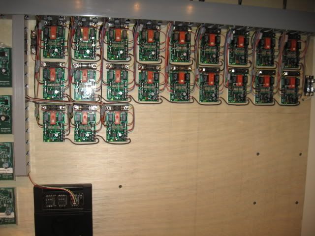
I don't have the #57 switches. I throw all switches with IC Controls ASC's  (Accessory Switch Controllers) and One SC-2, pictured, lower left, via a Cab-1/Command base system.


Last edited by Mike CT
Originally Posted by Dale Pancoast:

The #200 will work, but needs a #57  switch controller with red/green led's. No trackside confirmation. Paddle toggle and indicators may not agree with actual switch position (per Atlas). Looking to put led's inline with AIU and Master control panel.

I'm still new to all this and probably missing something here but, was thinking you could just power some LED's through the 2 sets of C/NO/NC contacts on the snap relay, with a wall wart or something? I thought all the #200 did was parallel the switch machine and give you 2 additional sets of contacts for other purposes, like switch position indication? Not sure what happens when override the switch manually, maybe that's what Atlas was talking about?

Turnout indication using Realtrax turnouts.


The Realtrax turnouts have red and green indication at the turnout.  I also have a Dispatcher Panel that also has red and green LED indicators which show the turnout position.  I use the signal directly from the turnout to power my LEDs. I just add a diode and resistor for each LED.  The Dispatcher Panel displays the status of all turnouts and blocks. See my Dispatcher Panel.


Note 1: I can operate each turnout using my DCS via the AIU or by using the RealTrax controllers or by using a small pushbutton panel. See attachment.


Note 2: Even if the turnout position is moved manually the Dispatcher Panel will always show the correct position.


MODEL RAILROAD DISPLAY PANEL

ROUTE CONTROL 001

Attachments

Images (2)
  • MODEL RAILROAD DISPLAY PANEL
  • ROUTE CONTROL 001
Last edited by pro hobby

Pro hobby, you're system is on the right track! Is the panel Led's "latched" to read the signal from the switch machines? Atlas twin coil switch machines do not have a signal output, so there is no intelligence to determine which way the coil is thrown. The Atlas snap relay does have monitoring terminals to attach Led's. The DCS AIU SW is only a momentary relay which triggers the switch coil, but too little or too much voltage will burn these coils out by merely holding the controller button down greater than momentarily! Thus the need for a capacitive discharge system with Led's to monitor position, trouble is, shut off the power and Led's forget which way the switch is thrown! We're going to solve this, question is how expensive does it have to be. MTH might be 

interested in our solution, as it will be a simple attachment to their AIU. Stay tuned.

Last edited by Dale Pancoast
Originally Posted by Dale Pancoast:

Pro hobby, you're system is on the right track! Is the panel Led's "latched" to read the signal from the switch machines? Atlas twin coil switch machines do not have a signal output, so there is no intelligence to determine which way the coil is thrown. The Atlas snap relay does have monitoring terminals to attach Led's. The DCS AIU SW is only a momentary relay which triggers the switch coil, but too little or too much voltage will burn these coils out by merely holding the controller button down greater than momentarily! Thus the need for a capacitive discharge system with Led's to monitor position, trouble is, shut off the power and Led's forget which way the switch is thrown! We're going to solve this, question is how expensive does it have to be. MTH might be 

interested in our solution, as it will be a simple attachment to their AIU. Stay tuned.

The MTH turnouts provide a latched indication.  I use this same latched signal with a series diode to provide a signal for my LEDs.


The attachment photos show my concept control board that shows a RealTrax turnout with a small pushbutton control box along with the hand controller supplied by MTH. As wired I can control this turnout three ways.  Using the RailKing controller, using the pushbutton panel or using my TIU/AIU combination.


000_0690

000_0691

000_0692 - Copy

000_0692

000_0693 - Copy

000_0693

Attachments

Images (6)
  • 000_0690
  • 000_0691
  • 000_0692 - Copy
  • 000_0692
  • 000_0693 - Copy
  • 000_0693
Last edited by pro hobby
Originally Posted by Dale Pancoast:

I'm looking at adapting Ken Stapleton's 751D circuit (momentary capacitive discharge to each coil) to monitor the position of the switch. Only problem is the circuit is 12VDC, probably not enough voltage to trigger the coils. Anyone have circuitry to accomplish this?


Why can't you operate his circuit http://www.classixaudio.com/pdf/751D.pdf at whatever higher DC voltage you think you need?  There's nothing I see in his schematic that limits this to 12VDC.  I'm not familiar with your Atlas switch but I'd think you might need more than 100uF based on other O-gauge CD designs I read about - such as from Dale H.


Originally Posted by Dale Pancoast:

Simply put, I'm trying to monitor the AIU relay positions. 

Not sure I agree with this.  Isn't the objective to monitor the switch position?  I'd think the contribution to the hobby would to come up with a method to modify the switch using some low-cost optical, mechanical, or whatever method that provides feedback as to the actual switch position.  But if you're saying it's OK to infer the switch position based on what it was last told to do, then why not use a $1 latching relay (one relay per switch) powered by a DC wall-wart supply?  The DC supply would be electrically isolated so the AIU would pulse the DC power to the latching relay (for LED indication) along with your existing AC pulses to throw the actual Atlas switch coils...no need for a separate CD circuit which also only indicates the last commanded switch position rather than the actual switch position itself.


Last edited by stan2004

My Dispatcher Panel indicates the actual turnout position at all times no matter how or when the turnout was selected..


Since the MTH/RailKing turnout provides a signal that indicates the actual turnout position my Dispatcher Panel always indicates the actual position no matter how the turnout was activated. I also have a small Route Panel that can select a route using small color coded pushbuttons. All turnouts can also be selected using my TIU/AIU combination.


ROUTE CONTROL 001

000_0516

Attachments

Images (2)
  • ROUTE CONTROL PANEL
  • DISPATCHER PANEL
Last edited by pro hobby

Stan2004:


I should have said monitor both the AIU throw and switch locations. Both AIU and another momentary switch are to have the ablity to trigger the switch coil. The coil (switch position) is to be monitored at it's physical location as well as back at the master switch panel with bi-pole leds. We want to prevent any back feed to the AIU as well, as to not mess up the AIU circuitry. Atlas twin coils leak to the led circuitry, so there is a need for a capacitive discharge to trigger the coil, and a relay with latching ability to monitor switch position. Of course with proper diodes to keep the current going the right way. Atlas's solution is, buy a #57 switch controller $11 and a snap relay $11 to monitor the switch position, with no control over the momentary holding down the switch button. Ala burn out the switch coil by neighbor's kids holding the button down!! The CD will prevent this, adding led position control.


Seems simple, but when you power off the circuit, the led's forget which way they were lit, until you throw the switch coil again.


Last edited by Dale Pancoast

Pro hobby:


You got it, execpt you have a RealTrax advantage, in having a latched circuit at the switch to monitor the position. Atlas twin coils (switches) don't have this.  I really like the fact, that you can monitor the switch position, no matter which panel switch or AIU, triggers the coil. What's in the panel box, looks pretty deep?

OK, I apologize for the slow uptake on what you're trying to do.  Some comments then.


1) I don't know if there's an official definition, but the 751D circuit in the link is not really a Capacitive Discharge circuit as the term is used for O-gauge switches.  That is, the energy to throw the switch is not being stored in a capacitor.  Instead the circuit uses a capacitor (and resistor) to turn on a transistor for a brief amount of time.  The energy to throw the switch is coming from a "beefy" 12VDC power source.  The circuit is such that the momentary switch to pulse the switch coils can be held down and you only get one pulse per button press.


2) The AIU, when configured in the two output switch configuration, is performing the same function as the 751D circuit.  That is, the energy is not being stored in a capacitor.  Instead the AIU has internal timing circuit to briefly pulse the switch coils.


3) So one approach is to have the AIU relays momentarily pulse DC voltage of sufficient magnitude to drive your Atlas coils.  Presumably this would be something more than 12V - maybe 16V DC or more based on your comments.  This same 16V DC supply would power the 751D circuit modified to handle more than 12V DC.  This is a simple modification choosing capacitors with slightly higher operating voltage (e.g., 25V type instead of 16V type).  The transistors would also be selected to operate at more than 12V.  These are trivial changes which probably won't even add to the cost.


4) By using a common supply for the AIU and the 751D circuit, they can operate in parallel so you can have DCS-AIU control at the same time as the momentary manual pushbutton switches for the kids.  Again, the AIU provides only a momentary pulse to fire the coils for command operation, and the 751D circuit provides only a momentary pulse to fire the coils for manual operation.


5) To handle the LED feedback/memory problem, simply use a latching relay.  The latching relay has a "set" coil and a "reset" coil.  Parallel the latching relay coils with the two Atlas switch coils.  So whenever one Atlas coil is driven, the mating latching relay coil is driven too.  Simply attach the desired red or green LED to the output of the corresponding contacts of the latching relay to indicate position.


6) You could even use the 751D circuit board if hand-wiring the circuit is inconvenient.  That is you wouldn't install the components associated with the LEDs since the LEDs would be driven by the latching relay outputs and it appears you want the single-package 3-pin bi-color LEDs anyway.


7) I really think it would be cool if you could figure out how to modify the Atlas switch with some kind of cheap sensor to indicate the actual mechanical position (like the Realtrax switches).  But if that's not in the cards, then so be it.  Presumably Atlas has been bombarded with this request so if they haven't done it perhaps there's good reason.

You can do this with a simple  Flip flop chip(HCF4013BEY is a is 14 pin DIP).

Available from DigiKey.com at low cost and any quantity.

Datasheet is on the website as well.

Hook AIU Switch output 1 to Set and 2 to Reset and your outputs Q & Q drive the LEDs,

Don't forget the resistors in line to the LEDs.

You get 2 circuits per chip.

39.2 cents each at qty 10 to 25. Shipping extra.


Last edited by Russell
Originally Posted by Dale Pancoast:

Pro hobby:


You got it, execpt you have a RealTrax advantage, in having a latched circuit at the switch to monitor the position. Atlas twin coils (switches) don't have this.  I really like the fact, that you can monitor the switch position, no matter which panel switch or AIU, triggers the coil. What's in the panel box, looks pretty deep?

These control boxes just have wires inside.  They are hinged boxes purchased at Michaels Crafts. They have a simple latch on the front to attach the lid.


Note: By pressing anyone of these pushbuttons one or more relays are activated. The "center" green pushbutton actually sets 6 turnouts for operating the route around the "outer loop" of the layout.


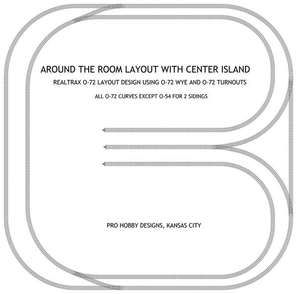
This is what my small around the room layout actually  looks like.


RAILKING REALTRAX LAYOUT WITH O-72 WYE AND DUAL O-72 CROSSOVERS

Attachments

Images (1)
  • RAILKING REALTRAX LAYOUT WITH O-72 WYE AND DUAL O-72  CROSSOVERS
Last edited by pro hobby

Guys, this is all good stuff, great ideas and thinking! Thanks much for the feedback.


Here's the direction we're headed. Separate Capacitive Discharge system to power the Atlas Twin coils, and a latching relay system to monitor the switch position with LED indicators at each physical switch location and another at a master control panel. Must have memory to cross sessions.


We are looking at design of the CD sytem  using a regulated power supply with enough voltage/amperage to trigger the coils (without burning them out). The separate latching system will probably be 12VDC, low power to simplify the led circuitry.


QUESTION:

Does anyone know the maximum amount of voltage/amperage before an Atlas twin coil #6099 fails? AC versus DC makes a difference. 


Experience is the mother of invention here.


Last edited by Dale Pancoast

Hi Guys, Anyone try the Flip Flop Chip? I could use some help. There are 14 pins on that chip! I have the pin information. Please check if I am right. I am using DCS with

a AIU that's working switches with Z 1000 motors. 12vdc to chip from HO transformer.

PIN   7   12vdc-

      14   12vdc+

      1 and 13 work Lionel 2 light dwarf signal (SW indicator light)

      2 and 14 work Lionel 2 light dwarf signal (SW indicator light)

      6 (set) AIU SW output

      4 (reset) AIU SW output

Thanks for any help that is given. Art


Art:

You got a mixed set up, Take 13 and 14 out for now

1 to Signal then to ground, 2 to Signal then to ground are your first set. 

The power flows thru the Signal to ground to light it.

Note, these will power an LED but not a bulb. You need relays for any serious power.

Power, 1, 2, 4 and 6 are correct.


Then 13 and 14 to another Signal then ground are another completely separate set.

Those are set and reset by pins 8 and 10 respectively.

this gives each signal 2 lights, only one will be set at any time.


As mentioned above, the chip loses memory when powered off.

Toggle each switch back and forth at startup of layout to validate position.

Kind of a hassle but alternately you can power this off a small wall wart and leave it on. Make sure the wall wart puts out real DC, most is just diode pulsed DC not full bridge, Add a Cap on the power to smooth it out.

Last edited by Russell

If I understand what you're trying to do, you're pulsing the "set" and "reset" pins of the HCF4013 chip with 12VDC (?) from AIU outputs.  In which case those pins will have nothing connected (except a long piece of wire) when the AIU SW output is inactive.  You need to "pull down" those pins with a resistor (e.g., 10k ohms, any wattage) to the "-" power pin 7.  This defines the input state when nothing is connected.  In fact you should "pull down" any unused input pins including the "clock" pin and any input pins on the other half of the chip if unused.  If an input pin is not used, it can be connected directly to the "-" power pin without a resistor.


As to the memory issue, Russell's wallwart idea is one approach but the battery alternative is not as far-fetched as it may seem.  You could even use a 9V recharge-able as used in engines with a small trickle charger (a resistor) to keep it topped off when powered.  4013 chips draw less than 0.000001 Amps when idle so a 9V battery could keep a handful of these chips alive for months.  The trick of course is to only power the 4013(s) and not the LEDs when on battery power - but that just costs a diode or two.

Post
The DCS Forum is sponsored by

OGR Publishing, Inc., 1310 Eastside Centre Ct, Suite 6, Mountain Home, AR 72653
800-980-OGRR (6477)
www.ogaugerr.com

×
×
×
×
Link copied to your clipboard.
×
×