I have a question for Gunrunnerjohn or others much smarter that me. I have gotten pretty deep into TMCC/Legacy but in S gauge and it looks as though S is being left behind here. I am looking for a way to convert the 19v AC power from my Powerhouses to smooth DC power 15v-20v that will fit inside an S gauge GP or similar engine and be used to power the Soundtraxx Blunami decoder. I am not sure of the components that I might need or if it's possible, so looking for some guidance.
Thanks
Ray
Level DC (Smoothing Pulsating DC)
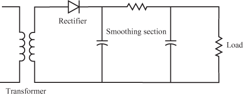
14 A basic power supply circuit can be divided into four sections, as shown in Figure 11.31.
Questions
A. If you use a center-tap transformer in a power supply, how many diodes would you need to produce a full-wave rectified output? _____
B. Will the power supply circuit shown in
Figure 11.31 result in full- or half-wave rectification? _____
C. What type of output will the rectifier section of the power supply circuit shown in
Figure 11.31 produce? _____
Answers
A. Two
B. Half-wave
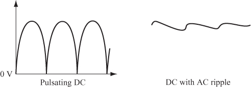
C. Pulsating DC
15 The function of the smoothing section of a power supply circuit is to take the pulsating DC (PDC) and convert it to a “pure” DC with as little AC “ripple” as possible. The smoothed DC voltage, shown in the illustration on the right in Figure 11.32, is then applied to the load.
The load (which is “driven” by the power supply) can be a simple lamp or a complex electronic circuit. Whatever load you use, it requires a certain voltage across its terminals and draws a current. Therefore, the load has a resistance.
Usually, the voltage and current required by the load (and, hence, its resistance) are known, and you must design the power supply to provide that voltage and current.
To simplify the circuit diagrams, ...
Smoothing capacitors are used to suppress voltage ripples, usually on power supply lines. They do this by periodically storing and replenishing energy. The image below shows a very common use case of these capacitors in a full bridge rectifier.
 As you can see, the smoothing capacitor discharges and replenishes energy when the output voltage drops. This "evens out" the output voltage, which is why this capacitor is called a "smoothing" capacitor.