I decided to make layout control panels with an active touch track plan diagram when I built my operating and switching 027 layout with total 28 switches, starting in 1976 or forty year plus years ago.  This is not a "set a speed" and watch the trains loop around or navigate the figure 8.  We run multiple trains, switch out engines, couple and uncouple cars and change engines from the turntable and round house, etc.

My Trains 4-18-2016 014

Note on Main control panel active touch layout diagram above:  The red and green push button switches are for track switches.  The blue push button switches are for uncoupling track sections.  The black slide switches are for cutting on and off power the track section they are on.  When WHITE  shows completing the white of the diagram, the power is ON.  When the BLACK of the switch slide lever is blocking the white track of the diagram, the power is OFF.


Model Railroading book shows an active touch track plan diagram control panel with 7 toggle switches located on the diagram.  Most Lionel train show room layouts had a track diagram but the switch control switches were not on the diagram and they layouts mostly consisted of 5 or 6 isolated loops with only a few sidings.  The book Greenberg's Model Railroading with Lionel Trains, Vol 11 of 1992, page 40 shows a control panel with 38 Lionel switch controllers lined up and sheet with the track plan below.  I do not know how they identify which Lionel switch controllers operates which track switch.

There are at least three reasons I chose an active touch track plan diagram control panel. 

One reason is I have 19 Marx 1590 track switches on the main train board and having that many switch controllers lined up would be difficult to operate deciding which control switch went with which track switch.  The active touch track plan diagram makes it easy to find the proper switch.  The uncouplers require an additional 14 switches to be matched with the uncoupler track section and would be hard to identify which switch worked which uncoupler track section.  An active track plan diagram control panel solves both these problems. 

A second reason is it saves space by combining  the switches for the track switches and uncouplers and on the small track diagram.  This is possible by using Radio Shack mini push button control switches which are located at the spot on the diagram where the track switch or uncoupler track is located on the train board. 

A third reason is I like the looks of an active touch track plan diagram as it is less cluttered than a large bank of Lionel switch control switches and seeing the track plan helps identify the different tracks on the layout.  Lionel used track diagrams to show a picture of the track plan on some of their showroom layouts but they did not have active switches to control the layout.


IMG_1285

 Note: The Main control panel has two LW transformers and will accommodate two operators.  One operator can operate the whole main layout with the red lighted LW on the left and a second train can be run on the green lighted LW on the right which then will operate the outside loop.  The inner loop and turntable will be operated with the red lighted LW on the Left.


IMG_1299

 Picture above of the Addition train board control panel with and active touch track plan diagram.  This train board can be operated with the orange lighted LW to the right, a part of total L shaped layout or as a stand alone layout.  The Additional train board can be operated with the green LW or with the red LW located at the Main control panel when part of the total layout.


One can see there is enough room for two operators at the left and that both control panels are close enough for one operator to work both control panels.

IMG_1288


This active touch track plan diagram control panel has proven to work very well and I can not imagine a better way to operate the track switches and uncoupling track sections for my layout.

After having this active touch track plan diagram control panel for over forty years, one idea for an improvement has been come up.  The improvement would be to have the direction of the switch on the diagram be illuminated in the route the tracks are set up to.  The operating engineers memory is required now to remember what route has been set on the various track switches. 

Further details for how I made the active touch track plan diagram control panel (post 8 of below link) , homemade $10 turntable and the whole layout are at my post title : 

https://ogrforum.ogaugerr.com/...51#60135595715990351

Charlie


Attachments

Images (2)
  • IMG_1299
  • IMG_1288
Last edited by Choo Choo Charlie
Original Post

Replies sorted oldest to newest

Charlie

I like your design and also for me it is easier than having banks of switches. I used Radio Shack push buttons and toggle switches depending on the switch motors used. I also used lights indicating the direction of the turnout.

Used toggle switches for power to track sections with indicator lights.

The red push buttons with black bases are for uncoupling sections.

This is a partial schematic with smaller control panels in areas where needed.

I used auto stripping tape of different colors.

Been using these for over 20 years and am very pleased with them.


Attachments

Images (3)
  • IMG_8704
  • IMG_8707
  • Wiring_6970
Last edited by sidehack

Thanks for the response. 

Ray I like your active diagram control panels and the neat appearance of your wiring under the panel.  I should have used terminal strips like you when soldered flexible lower gauge wire pig tails on my 14 ga track wire and 18 ga switch wire.  My under panel wiring is a real mess.

I see you put track section indicator lights on the control panel.  To put an indicator light on each section on my layout  would show whether that section was live or dead as most of the tracks between switches are all either live or dead.  I can see if they are live by looking at my slide switches with the black switch slide part being black and when switched to live, they are white like the 1/8 inch pin stripping.

Like I stated, a good improvement to my control panel would be panel push button switches with indicator lights to stay on in the direction the switch is set.  Please let me know how your switch direction lights or switches work to show the position the switch is thrown too.

Charlie


Last edited by Choo Choo Charlie

My panel, made all switches 12volt DC. Track blocks are yellow, switches either red or green depending on direction (all tortoise) with bidirectional leds. Green button switches are uncouple. I used auto relays for the blocks controlled by the 12volt switches, the tortoise are 12 volt. the other large switches )blue) control the power in and the other large ones control lighting in areas of the layout Changed all buildings to 12volt dc leds.

The panel itself was printed on an aluminum sign product called Diebond which available at Fedex Office. I mdae a PDF of my track plan from RR track software that I used to design my layout. They were able to print it directly on the Diebond.

P3230005

321

Metal Signs

Made of a durable aluminum composite, metal signs are ideal for long-term outdoor advertising and real estate signage. These aluminum signs feature single- or double-sided full-color printing and offer the longest life of any signage material.

You can pick up your order at a FedEx Office location

Attachments

Images (2)
  • P3230005
  • 321

Charlie

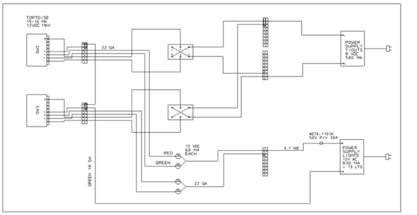
I am using toggle switches with Tortoise motors on most of the turnouts and the red and green lights from Radio Shack are connected to the Tortoises as shown in picture.Turnout Schematic_1

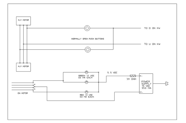
I use NJ1's to switch my crossover turnouts (I like that they are fast and positive) with push button switches and the lights are connected to to NJ1's as shown.

Turnout Schematic_2

Eric, that is one fine looking control panel, well done!

Attachments

Images (2)
  • Turnout Schematic_1
  • Turnout Schematic_2

Ray

Thanks for the info on the light indicator on your Tortoise motors.  My Marx 1590 switches have two solenoids and they are unpowered after changing position.  I will have to check them out to see if a contacts or micro switches could be added to somewhere to provide a signal to operate two lights per switch.  It would have able to be added without removing the Marx 1590s from the layout (removing 28 switches from a built layout is a Big chore!).  I would probably only add lights on the most used switches.

Charlie

Like a lot of you, I’m working on a control panel... quite a puzzle!  Of course, almost all of the “real estate” has layout and that makes finding a large enough spot for the panel is tough.  I’m using Ross Custom Switches with the controllers that come with them, all pumped through Lionel SC-2 units.  

One problem is the DZ-1002 controllers take up all the space on the panel face, some 20 switches for the freight yard and steam engine yard alone.  I was looking to switch from those to Momentary Push Button switches (two per switch and smaller by far).  Does anyone know where I can find green and red push button switches?

if anyone can post pictures of your control panels and how you wired them up, I would appreciate any hints and tips.

Add Reply

Post
The Track Planning and Layout Design Forum is sponsored by

AN OGR FORUM CHARTER SPONSOR

OGR Publishing, Inc., 1310 Eastside Centre Ct, Suite 6, Mountain Home, AR 72653
800-980-OGRR (6477)
www.ogaugerr.com

×
×
×
×
Link copied to your clipboard.
×
×