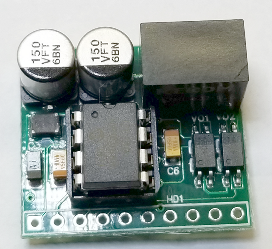
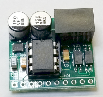
Here are a few pictures of the revised version of the PCB for my lighting project(s). These pictures were taken with my camera so they are a little better than the iPad pictures in the conversion thread.
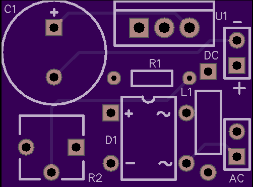
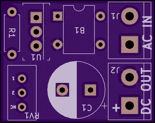
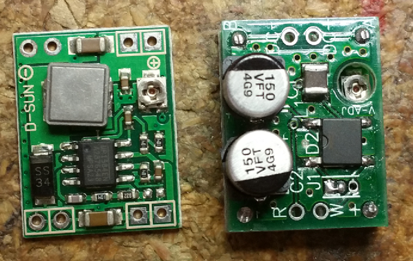
Top and bottom of version 1.0.2.

Comparing length of this board to the original version.

Comparing width.

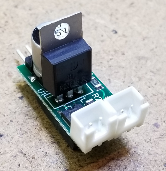
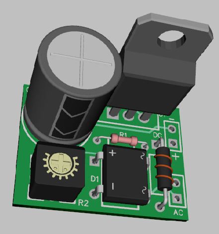
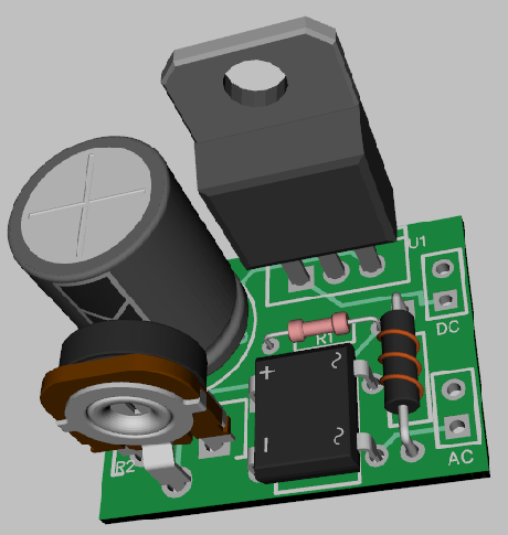
PCB populated with same components as original version. I will say it was more work to solder the components to the board this time as it was harder to hold everything in place and apply the heat and solder.

Even though it was harder to populate the PCB it does work. 

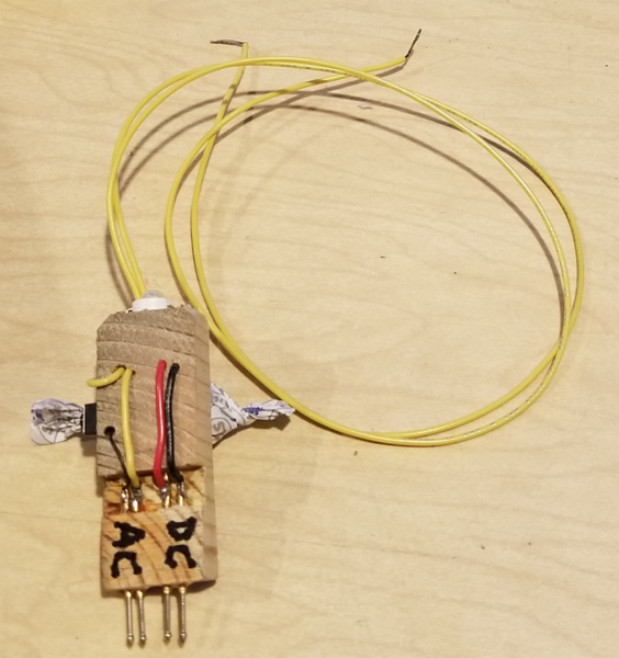
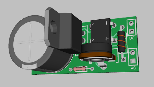
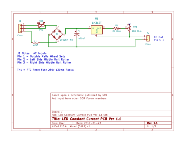
I was a little concerned, but both connectors do fit on the revised PCB. However, I plan on using only one connector on the remaining boards. I will solder the supply wires directly to the PCB's AC IN pads along with a PTC to protect the wires. Since the PCB is attached to the floor of the cars' with double sided tape, one connector for the DC OUT wires will be sufficient to allow me to completely detach the roof if needed in the future. Paint the roofs white maybe?
Okay, breaks over, back to soldering. Well maybe later.
Edited*** I ended up using connectors for both the AC input and the DC output. Since I am using the original wiring from the wheel sets in the PE cars, it was just easier than trying to solder the wires directly to the board.


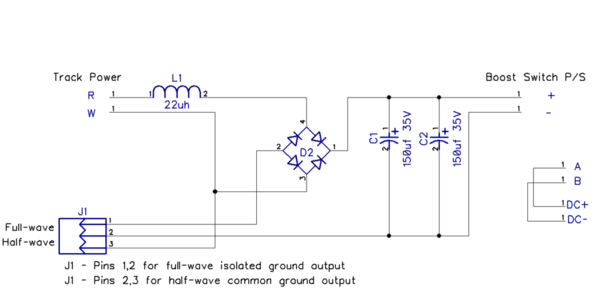


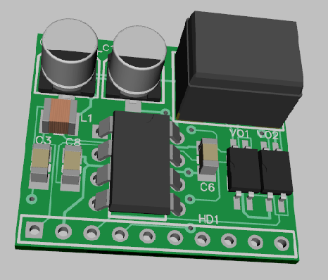
 3D")
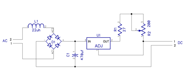
 Schematic")
 3D")
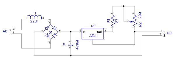
 Schematic")