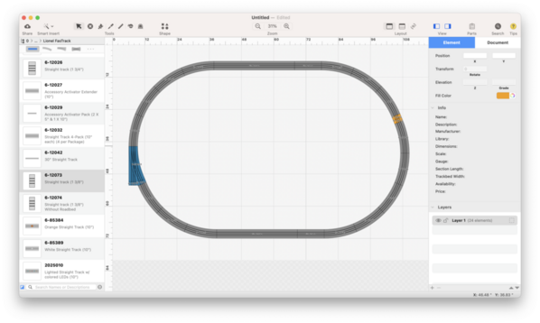
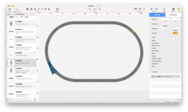
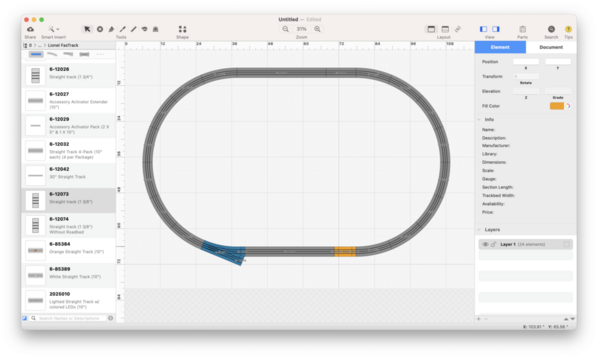
Hello everyone, I have read a few different threads on similar topics and need some assistance. As I have learned, O-60 switches have an additional 1 3/8" of straight track attached at the beginning of the switch which throws of the geometry if you are replacing a curve with a switch. I have a simple loop at the moment of O-60 and am trying to replace a curve with a switch for entrance to my yard. To accomplish this, what exactly can I do? Do I need to place a piece of 1 3/8 at joint "B" on my crude drawing? And also, if the opposite side of the loop is 40" long, what length of straight track do I need on the "switch side"?
Thanks for all of your knowledge on this topic.
Note: I own a MacBook and apparently an not able to download SCARM or any additional track planning software that could help me here.