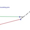
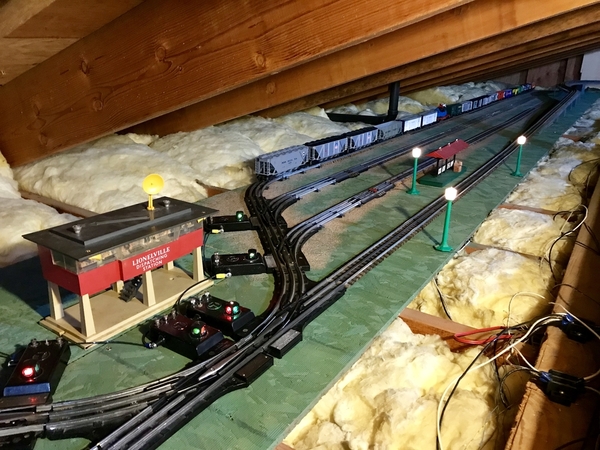
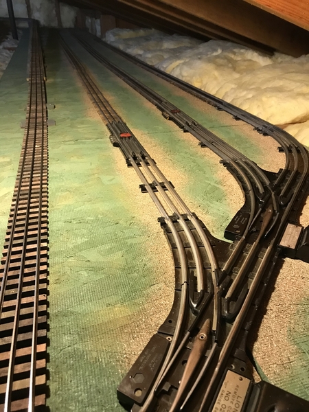
I want to make 2 of my sidings "longer" so I can store longer trains headed by a locomotive. I already have put insulating pins and on/off power to each siding. Howvever, to make my block longer I want to move the insulating pins right to the turnout. Can this work? I am using K-line supersnap track and O Gauge Reproductions O31 switches. I am worried that I'll have insulating pins on the outside rail and in the center rail of the switch (see picture. Will this affect switch operation? Thanks.
Replies sorted oldest to newest
This will work electrically, there can be a problem physically. If you are screwing track and switches to bench work it should be OK. Perhaps some screws right near this track joint. I have built a lot of floor layouts with tubular track and O22 switches and this can be a problem as it is not screwed down. I have used a short stub of track at the switch to move this pin away from the switch a few inches.
No problem with what you want to do. It'll work perfectly fine.
NO problem whatsoever!! All you need is an insulating pin on the “Hot” Trackpiece & a separate Power Feed! Do it all the time& it works great!!
Fredstrains
ogaugenut posted:This will work electrically, there can be a problem physically. If you are screwing track and switches to bench work it should be OK. Perhaps some screws right near this track joint. I have built a lot of floor layouts with tubular track and O22 switches and this can be a problem as it is not screwed down. I have used a short stub of track at the switch to move this pin away from the switch a few inches.
I recently installed six blocked sidings off one of my main lines. I ran hot to the center rail close to the insulated pin, which is directly adjacent to the switch. Now, even though I am using constant voltage to the switches, they get brighter when I run locomotives on the sidings. I'm feeling like maybe the sidings need to be grounded somehow? Interestingly, the dozen other switches on the layout do not experience any voltage fluctuation even though they are all fed (daisy chained) from the same hot wire.
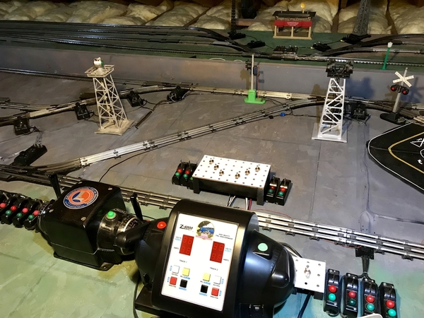
Any recommendations on how to test my ground hypothesis? Perhaps the switches themselves need to be grounded, rather than the sidings? The switches get power from a ZW, and the trains from a Z4000. The common side of the transformers are bridged together, if that matters.
Thanks for any suggestions!
Kevin
Attachments
You should jump power around switches vs through them. E.g, I.e. 3 feeds per turnout, and not just the center on old pieces imo. But another e.g., 2 switches to a smallish parallel siding would only need 4. Two for the sw entrances, one between switches on the siding, one between them on the main.
Mulitiple transformers? Double your common wire guage, especially if you didn't go with plenty of overkill on wire gauge. Common is doing work for both units now so that wire gets sized for the total combined max amps of all P.Supplies that use that common wire .
( I recently realized we don't point that out enough, if at all. While on my mind, for dc I use a gauge fatter for ground than hot and fuse hot out of habit as some applications simply need it to be rock solid)
If things go brighter as you cross joints/switches, your feed or pins there are weak and rollers&wheels are improving it.
If it is at block seperation it could be some other rather deep theory (along the lines of phasing/loops) is at play. They are phased together right? If not, stop running right now, shut off the power. Then watch the Lionel video on Youtube: "Phasing two or more transformers for use together and why"... but I think the Z-1k would blink out (breaker) if they were not in phase. I know my newer Lionels blink out if not in phase.
Even thougb you use constant power, which is an improvement for the sw. motor and light, it is still drawing from a transformer doing other work so flickers wont be 100% eliminated, but nearly so; lets say 95%. Having their very own transformer would be closer to say 97%. If that is isolated from other power 98%. ( the wall power and ac itself holds the other elusive 2%. DC has no frenquency of polarity change & 0volt time seen in each ac cycle at 60hz (cycles per second)
Adriatic posted:You should jump power around switches vs through them. E.g, I.e. 3 feeds per turnout, and not just the center on old pieces imo. But another e.g., 2 switches to a smallish parallel siding would only need 4. Two for the sw entrances, one between switches on the siding, one between them on the main.
Yes, I'm going back and adding more power at a number of places on the layout.
Mulitiple transformers? Double your common wire guage, especially if you didn't go with plenty of overkill on wire gauge. Common is doing work for both units now so that wire gets sized for the total combined max amps of all P.Supplies that use that common wire.
I'm using #14 on the entire layout.
If things go brighter as you cross joints/switches, your feed or pins there are weak and rollers&wheels are improving it.
Interestingly, I phased the two transformers last night (they were out of phase) and now the switch lights get dimmer.
If it is at block seperation it could be some other rather deep theory (along the lines of phasing/loops) is at play. They are phased together right? If not, stop running right now, shut off the power. Then watch the Lionel video on Youtube: "Phasing two or more transformers for use together and why"... but I think the Z-1k would blink out (breaker) if they were not in phase. I know my newer Lionels blink out if not in phase.
My Z4000 did not blink even though out of phase with the ZW. Possibly because the only thing I have connected to the ZW is lighting and switches. In any case, I am now in phase.
Even thougb you use constant power, which is an improvement for the sw. motor and light, it is still drawing from a transformer doing other work so flickers wont be 100% eliminated, but nearly so; lets say 95%. Having their very own transformer would be closer to say 97%. If that is isolated from other power 98%. ( the wall power and ac itself holds the other elusive 2%. DC has no frenquency of polarity change & 0volt time seen in each ac cycle at 60hz (cycles per second)
I think I should be able to get to the 97%. That would be good enough for me.
Thank you so much for the thoughtful reply - super helpful. I'm in the process of running more common to the track, and in particular to BOTH outer rails of the Gargraves, which I didn't have before. Fingers crossed!
Kevin
Update: Adding additional common connections to the outer rails, near the switches and sidings, made all the difference. No more flickering at all, and much better engine performance through the switches.
Man, I sure am learning a lot through this hobby!
Your at the edge of my acceptance for wire gauge; especially at that distance. I like wire gauge overkill for the amp delivery and some extra safety "above and beyond".
One lighter wire size shorted will have less than half the time till meltdown if something bad happened. Fuses would excuse
Real simple; I hate re-wiring meltdowns; and when that is contagious to neighbor wires; I meltdown 😕 .... I like fuses too😬
My wire can take a full throttle total short for a looong time without getting in trouble. That lets the ZW thermal breaker do the work, an external fuse/breaker can save that the extra effort and extend it's life that way as well. It's really there for the transformer and the fresher the better.
If you're running command only, you are a little better off. Maybe get a signal drop on dcs with 12g?
But in general I strongly suggest a (fused/breaker), heavier 12g bus system for all that juice and distance if you can. It should pay off big in running any conventional up that grade. You can keep 14g drops and just run the distance a bit larger.
E.g. if all those commons are tied to one block/etc. and are fed by one 15' wire I'd need 10g there in order to sleep well if things were left on or something. 8g would be kinda expensive at that length, lol.
Did I mention fusing outside of the transformer? ![]()
Gondolawillie posted:I want to make 2 of my sidings "longer" so I can store longer trains headed by a locomotive. I already have put insulating pins and on/off power to each siding. Howvever, to make my block longer I want to move the insulating pins right to the turnout. Can this work? I am using K-line supersnap track and O Gauge Reproductions O31 switches. I am worried that I'll have insulating pins on the outside rail and in the center rail of the switch (see picture. Will this affect switch operation? Thanks.
No problem - only the center rail needs to be isolated with insulating pins and a toggle switch for the Hot wire to the center rail - keep the common intact
Adriatic posted:Your at the edge of my acceptance for wire gauge; especially at that distance. I like wire gauge overkill for the amp delivery and some extra safety "above and beyond".
One lighter wire size shorted will have less than half the time till meltdown if something bad happened. Fuses would excuse
Real simple; I hate re-wiring meltdowns; and when that is contagious to neighbor wires; I meltdown 😕 .... I like fuses too😬
My wire can take a full throttle total short for a looong time without getting in trouble. That lets the ZW thermal breaker do the work, an external fuse/breaker can save that the extra effort and extend it's life that way as well. It's really there for the transformer and the fresher the better.
If you're running command only, you are a little better off. Maybe get a signal drop on dcs with 12g?
But in general I strongly suggest a (fused/breaker), heavier 12g bus system for all that juice and distance if you can. It should pay off big in running any conventional up that grade. You can keep 14g drops and just run the distance a bit larger.
E.g. if all those commons are tied to one block/etc. and are fed by one 15' wire I'd need 10g there in order to sleep well if things were left on or something. 8g would be kinda expensive at that length, lol.
Did I mention fusing outside of the transformer?
Helpful, thank you. The longest runs of track power are about 30' from the transformer. Probably would not hurt to make that 12g.
I notice that when I put my multimeter on the ZW, when I set the handle at 14v it will read 14v with no load, but when I attach the load to it, it drops a couple of volts. Is that normal? It's only a few dozen lights so I was surprised to see that. Same thing happens on the other handle with the 022 switches.
A couple volts is kind of a lot. It sounds like the ZW (post war?) may need new contact rollers.
cjack posted:A couple volts is kind of a lot. It sounds like the ZW (post war?) may need new contact rollers.
That is quite possible. Never been done, as far as I know. We have had it since '76. I'll order some and watch the video on how to do it. Thanks!
Some drop, but check as Chuck noted. Where do you measure? You'll get more drop over a distance if there isn't enough path. Could be ZW rollers, could be wire gauge, could be connections. What kind of load, 2a or 5a? All are factors.
If you have plenty of 14g you can double it up, triple it, or whatever. You add up the combined amp capability to reach a goal .
He said "when I put my multimeter on the ZW" so I figured it had to be the rollers or at least inside the transformer.
cjack posted:He said "when I put my multimeter on the ZW" so I figured it had to be the rollers or at least inside the transformer.
Yep, that’s right. Same voltage whether measured at the transformer or anywhere else on the layout.
CoastsideKevin posted:cjack posted:A couple volts is kind of a lot. It sounds like the ZW (post war?) may need new contact rollers.
That is quite possible. Never been done, as far as I know. We have had it since '76. I'll order some and watch the video on how to do it. Thanks!
Oh man, pull the four screws on top and pull up.
Hopefully there is no sawing by arms with bad rollers. Wear, nicks ect. have a large impact on amp capabilities of the unit. Windings arent really repairable, but a "bad" one might still serve well for light duty work on lights or accesories.
Rollers should roll free, no flat spots, no skidding. If you replace them buy extras, and axle pins, order double the extra. (really cheap, so not worth not getting extra). It isn't a hard job per se, but it is easy to crack a roller or over set the pin head (long, thin, tiny rivet). If you over set it, the pin will bend and the roller will not roll as well on a bent axle (pin). Some folk use cotter pins instead, but check those more often. The pins are smoother for the foller hub. Roller are like brushes; graphite.
Get in the habit of checking these every once in a while, it's too easy to check to ignore it.
Also note the feel of throttles closely. If that feel changes, time to see why... right now!
Adriatic posted:CoastsideKevin posted:cjack posted:A couple volts is kind of a lot. It sounds like the ZW (post war?) may need new contact rollers.
That is quite possible. Never been done, as far as I know. We have had it since '76. I'll order some and watch the video on how to do it. Thanks!
Oh man, pull the four screws on top and pull up.
On my list for tonight!
Also, I have read that some people solder instead of riveting. Will that work?
CoastsideKevin posted:Adriatic posted:Your at the edge of my acceptance for wire gauge; especially at that distance. I like wire gauge overkill for the amp delivery and some extra safety "above and beyond".
One lighter wire size shorted will have less than half the time till meltdown if something bad happened. Fuses would excuse
Real simple; I hate re-wiring meltdowns; and when that is contagious to neighbor wires; I meltdown 😕 .... I like fuses too😬
My wire can take a full throttle total short for a looong time without getting in trouble. That lets the ZW thermal breaker do the work, an external fuse/breaker can save that the extra effort and extend it's life that way as well. It's really there for the transformer and the fresher the better.
If you're running command only, you are a little better off. Maybe get a signal drop on dcs with 12g?
But in general I strongly suggest a (fused/breaker), heavier 12g bus system for all that juice and distance if you can. It should pay off big in running any conventional up that grade. You can keep 14g drops and just run the distance a bit larger.
E.g. if all those commons are tied to one block/etc. and are fed by one 15' wire I'd need 10g there in order to sleep well if things were left on or something. 8g would be kinda expensive at that length, lol.
Did I mention fusing outside of the transformer?
Helpful, thank you. The longest runs of track power are about 30' from the transformer. Probably would not hurt to make that 12g.
I notice that when I put my multimeter on the ZW, when I set the handle at 14v it will read 14v with no load, but when I attach the load to it, it drops a couple of volts. Is that normal? It's only a few dozen lights so I was surprised to see that. Same thing happens on the other handle with the 022 switches.
"It's only a few dozen lights so I was surprised to see that".
That makes sense - the incandescent bulbs draw some current, especially 24 - 36 of them
The switches draw about 1.5 amp when they are thrown, but the constant current is only the indicator lanterns - are there a lot switches?
"It's only a few dozen lights so I was surprised to see that".
That makes sense - the incandescent bulbs draw some current, especially 24 - 36 of them
The switches draw about 1.5 amp when they are thrown, but the constant current is only the indicator lanterns - are there a lot switches?
There are 18 022s on the layout, and the controllers all have incandescent bulbs too.


