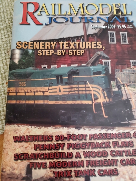
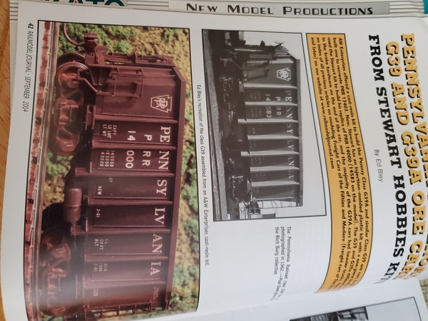
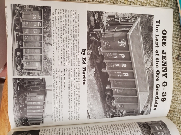
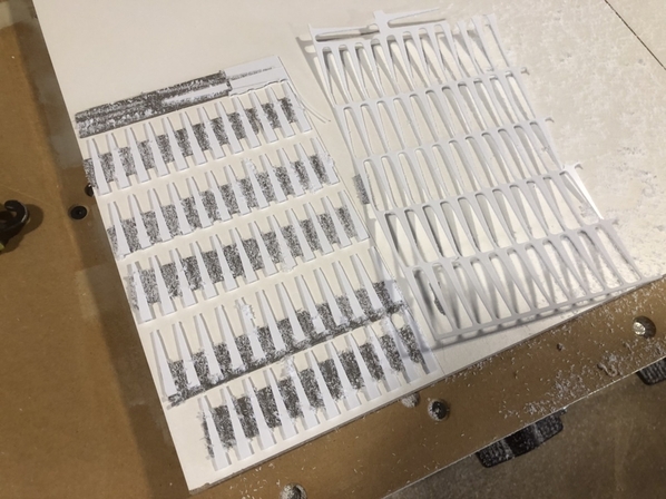
I’d mentioned in my Erie DUNMORE Caboose thread about also working on a PRR G39 ore jennie project.   I’ve always liked these cars, and they are appropriate for the time period I model - Penn Central era, 1969-1976.   I’ve also recently purchased two Alco C630s (need one more for effect) that I intend to paint for Penn Central.  Nothing like a trio of grimy, black, Penn Central giant Alcos and a mineral train of G39 jennies.   The trouble is I will need a lot of them.   So back to the CAD drawing board, designing parts for the laser to cut out.  

BBCC2E1A-97DA-4705-A122-1027C6D6840E

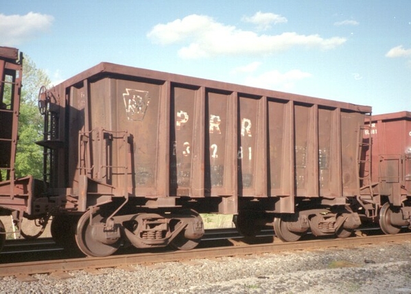
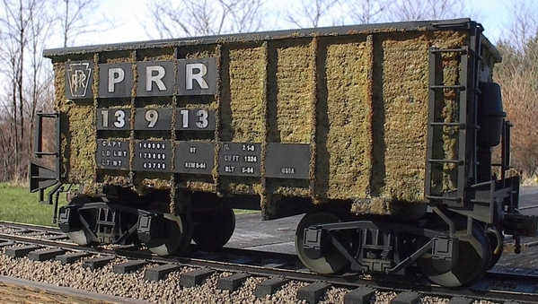
G39, well I think this is a G39a.  The difference between the two is the A had the air reservoir and valve gear mounted on the exterior of one end.  The G39 had all the brake gear underneath.  PRR and Penn Central painting these cars black, Conrail repainted them mineral red.  This is a faded Conrail paint job.  

If you haven’t read my Erie Caboose thread, the laser is of course for speed and accuracy cutting out parts (something I don’t enjoy doing anyway), but it also is great for adding tabs, location marks, etc., to speed assembly, and to self align parts.   Like with the Erie Caboose, I work out the body first, then the under frame.  This usually means two test assemblies to work out all the bugs and measurements, but I buy plastic in 4x8’ sheets, in bulk, so it isn’t expensive to do.  

E5D665B8-0D35-43CA-8A5E-3EBAB44EB6A8

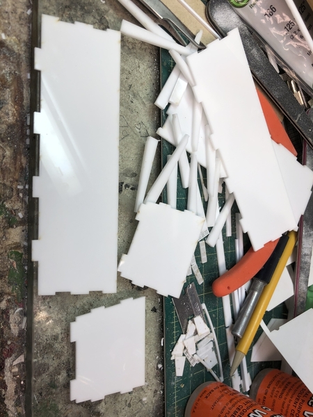
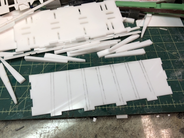
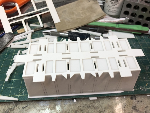
The parts for the body.

80B5370E-F637-4ACF-B25D-676290E71EC4

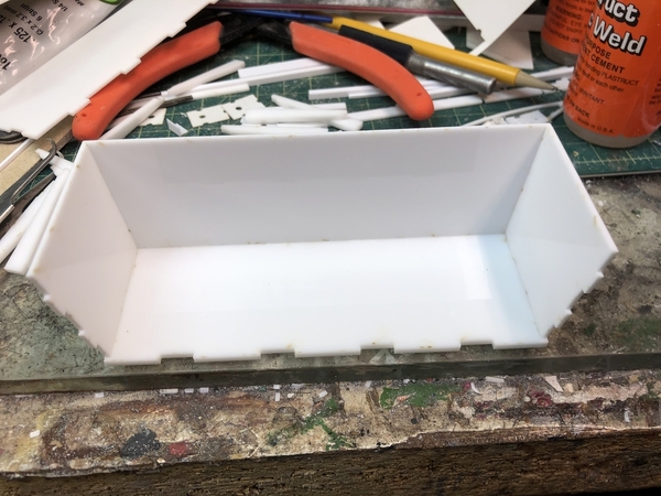
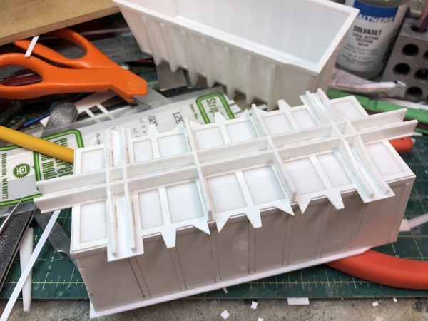
Partial assembly - note the tabs.  There is no guess work here, and assembly fits together and stays in alignment without clamps, rubberbands, or tape. 

8479F386-25F5-4F3B-BE6B-65D12A45596D

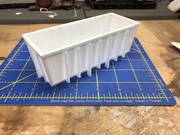
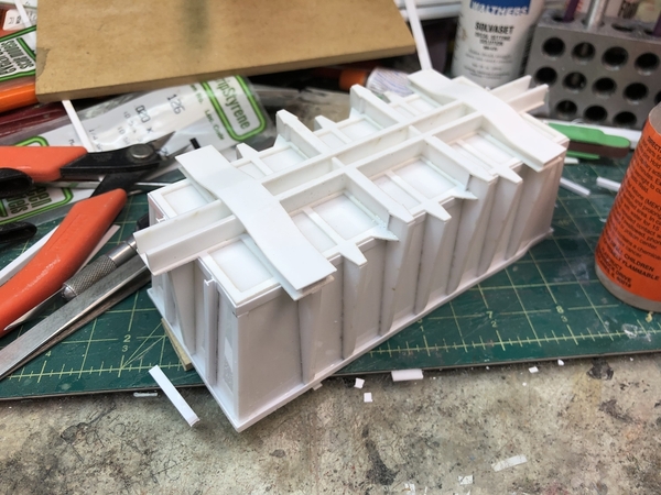
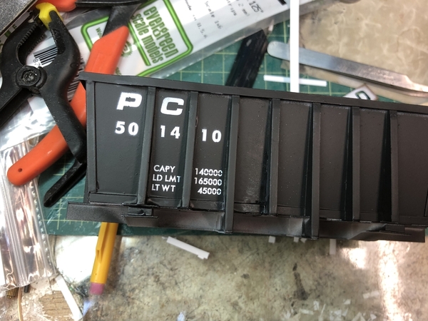
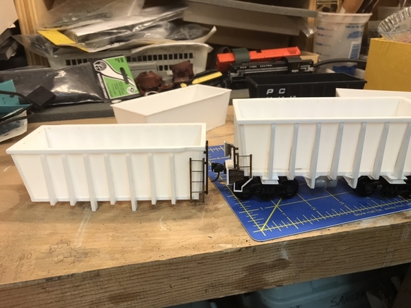
Assembled car body, minus under frame and details.   The rim of the prototype car is intentionally indented on opposing sides for the ladder.  The ends and sides are .060 acrylic, and the bottom they tab into is .125 acrylic. The corners and perimeter of the bottom have angles and strips applied to conceal the tabs, and replicate similar plates on the prototype.  I used .020 styrene, but will used .010 (was out of it) ; and the corners are .100 angle, but I’ll reduce those to .080.    The rim of the car is a single piece of .060 acrylic cut out on laser, with .125 wide strip styrene applied around perimeter.  The styrene conforms to the indented ends with a little help from clamps.   A few problems that will be corrected in next test - the rim needs to be slightly longer on the ends to flush it up on inside and provide more outside overhang.  Also the ribs themselves need to be reduced slightly, and the angle at the top adjusted a bit.  They are also a little too thick compared to the prototype.  The problem is I have .125 and .060 acrylic to work with, but really could use .080.    I can get this thickness, but only in clear, and since my supplier doesn’t carry, I’ll probably pay online for a one foot square piece, what I would pay for a 4x8 foot sheet.   The bigger problem is plastics suppliers are cleaned out of clear acrylic because of Covid-19.   I might just stick with the thicker ribs if supply is an issue.  

Jim

Attachments

Images (4)
  • BBCC2E1A-97DA-4705-A122-1027C6D6840E
  • E5D665B8-0D35-43CA-8A5E-3EBAB44EB6A8
  • 80B5370E-F637-4ACF-B25D-676290E71EC4
  • 8479F386-25F5-4F3B-BE6B-65D12A45596D
Original Post

Replies sorted oldest to newest

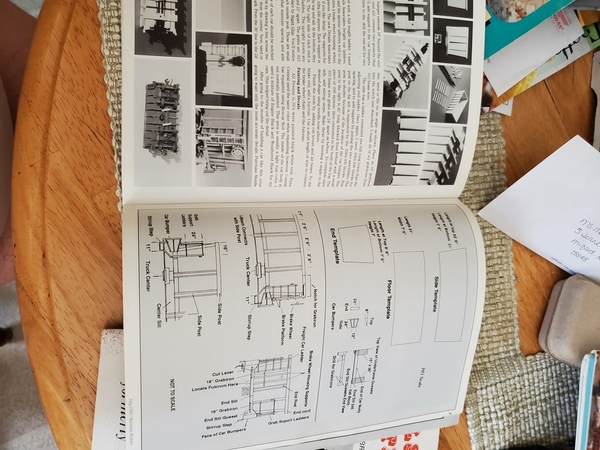
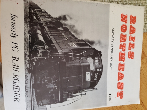
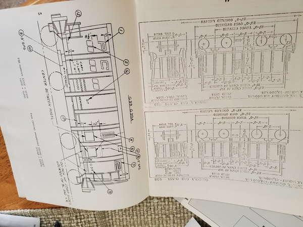
Thanks PRR Horseshoe Curve for the references.  I have had the Mainline article but hadn’t seen the other two, although I did find the same plan in Rails Northeast online.   As a benefit to posting on here, George Losse had drawn some most excellent plans of the G-39 from measurements he took of an actual car, and contacted the President of the Cherry Valley club, John Dunn, who forwarded me his email.  Within a day I had super accurate and detailed O-Scale drawings to work on.   They did confirm what I suspected about the test body I had built - it was too narrow, by almost a scale foot.    I altered my CAD drawings to reflect this, along with additional under frame parts.    This bag has all the Laser cut parts for the majority of the car body and under frame, except for some strip styrene.  
087416A0-DECE-4AD6-96D8-4112DE2717CB

There still are a number of details to drawn and cut before I’d say I have a complete set of parts.

5D7F026A-A19A-4342-B6BB-02869679777E

I rubbed some pencil lead on the side of the car to show the laser cut location marks for the ribs.  Also note the car bottom in background is now slotted for tabs from the under frame parts.  Again, the location marks and tabs are to make assembly fast, easy, and take out any measuring or guesswork.  

3A077FF9-49E4-41E3-AC34-036C96D8637B

Gondola assembled to bottom and .020 laser cut styrene plate added.  

8FE5FBCF-E871-4CD8-A858-46D52EF5714F

Center beam, bolster, and main I-beam webs installed.  These are .060 acrylic and have tabs to insert into car bottom, and slots to mesh with each other.  Perfect alignment without hassle.   Slots are slightly too big and will tighten up a bit on final product.  

B539FB5F-1383-446C-ACBA-A370BD02F66F

Second .020 styrene web added.  Forgot to continue across at center beam/main crossbeam intersections.   Also the bottom .020 web is slightly too small - matches car bottom, but not the .020 strip around the car side.  Will adjust this out slightly.  

349D02FC-5643-4B36-8035-55DF17B94729

You can see the difference in width between version 1.0 and version 2.0.  As I was taking this photo I realized I installed the gondola top plate reversed.  The indents should be on the opposite ends - when looking at car from side, indented top (space for grab rail/ladder) is always on the right.   It’s a one piece .060 laser cut acrylic. I would hope not to do it again, but I might have to add some writing on the bottom to warn me.    You can also see the underframe tabs, which are cut through on the bottom.   I may add a laser cut .020 styrene piece to glue in to hide, although, I plan on modeling loaded cars so not totally necessary.   I also still have to work out the coupler mounting.  I may not use Kadee boxes, and instead just mount the coupler only.  These cars are short, so shouldn’t need much swing, and they will be mostly coupled as one unit train.    Test version 2 took 80 minutes to assemble to what is shown.  I imagine I should be able to get this down to an hour in future.  Ladders, brake rigging and other details will probably take another few hours.   I’d like to be around 3hrs per car sans painting.  


Attachments

Images (6)
  • 087416A0-DECE-4AD6-96D8-4112DE2717CB
  • 5D7F026A-A19A-4342-B6BB-02869679777E
  • 3A077FF9-49E4-41E3-AC34-036C96D8637B
  • 8FE5FBCF-E871-4CD8-A858-46D52EF5714F
  • B539FB5F-1383-446C-ACBA-A370BD02F66F
  • 349D02FC-5643-4B36-8035-55DF17B94729

Jim,

Great looking car! Glad I could help.

Someone pointed out the Rails Northeast issue. That was the one I couldn't remember when I emailed you. If you don't have it, let me know. I have it, just have to find it. I'll dig it out and make scans of the article for you.

You might want to think about a second floor inside the car that you could sandwich a steel plate in between.  These cars are short and they will still need to have weight added to them.

George

Good idea George on steel weight before I glue in a floor.  That’s a very nice car PRRK4.  How did you do the foam insulation.  I’d like to do a few cars with the foam, but hadn’t wrapped my head around a technique yet.  Lots of tests and experimentation down the road no doubt.   Speaking of experimentation - while working on the part designs for the end details, I am also playing around with the idea of using stencils for the lettering as opposed to decals.   I primed and sprayed the latest test body black, and then used laser cut stencils to test spraying the lettering via an airbrush, just like the real railroads.  

7F563C55-10D4-44F5-AD74-997F80CBB257

The results were not as good as I’d hoped, but there is a lot of room for improvement in the stencil/lettering design and the masking/spray technique.   I also, in a rush, grabbed the crappiest 0 brush on my bench to paint out the stencil lines, making things worse than they should have.   If I can tighten things up a bit I think this is a viable method.  To be sure, printed decals would be crisper, however I apply 5-10 layers of filter weathering, along with oil paint, and chalks, which would mute most of the deficiencies of the stencil method.  On the plus/pro side of the equation - no decal film to attempt to make invisible - quicker application of lettering - lower cost - super accurate alignment of lettering, without touching a ruler.  

6F74C289-6D8F-4F5B-9C12-87696C5B85B8

For a multiple car run like I am doing, having decals made would be economical, but if refined, this method would really be useful in one-off car builds.   And again, this is just a test car - sloppy glue up, rushed paint job, etc.  

I just guessed, but does anyone know the correct PRR or PC lettering sizes?  I did 12” for the PC, 8” for the numbers, and 4” for the car data.  

Attachments

Images (2)
  • 7F563C55-10D4-44F5-AD74-997F80CBB257
  • 6F74C289-6D8F-4F5B-9C12-87696C5B85B8

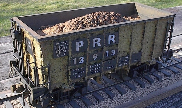
g39a2Jim, I modeled the foam insulated G39a models years ago. First in HO scale, then in G Scale. I looked for my photo files for the G Scale version but couldn't locate the steps I took to apply the insulation. So I looked for my HO photos. I found one with the insulation as it look when first applied. It's included here as well as the two completed models I did in HO. To represent the foam I used woodland scenices ground foam mixed with either clear Elmers Glue, OR, I cant remeber for sure, that medium used to make water falls and ripples in water scenes. I believe it is from woodland scenices as well. Its a thicker, tackier substance. When actually applying the foam mix to the sides of the car I do know I used the water fall / ripple material. Sparingly applied to the car and with a piece of styrene used as a spatula, I applied the foam mix and worked it to get a "sprayed on" look. Once dried I proceeded to finish the model build and weathering. On foam insulated G39a cars the lettering is applied to panels attached to the ribs. Also, if your familiar with the Woolies, you will note the foam eventually failed by flaking off. I represented one car with patches of missing foam. These HO cars, as well as the G Scale car were done I believe in 2004. Everything held up well over the years. Have funDSC00383

Attachments

Images (2)
  • g39a2
  • DSC00383

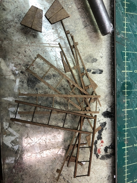
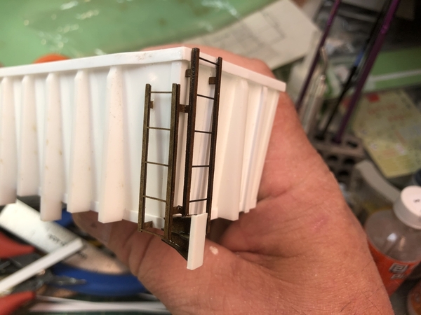
I’m hoping to get back working on the G-39 next weekend.  I did start working on some of the details.  I devised a corner ladder assembly of sorts, made from poly-backer.  The ladders are three pieces and a bit of a pain to assemble the angles with ACC.  I’m on the fence as to whether it will be a fast enough method for these car.  In the close up photos, the cross section of angle ladder sides looks big, but not so much from afar.  I still might reduce a little.  I also experimented with adding a .020 brass rod on top of the wrung.  This gives it some dimension and I think I will do this, despite the time it will take.    

DA5179EF-1D01-42CA-8C6A-7BC967CD4C49

620D28E3-E9A7-4DFB-9CC2-675FFBEE35C5

I also mocked up the pusher bumper.  I used a partial styrene channel for the end, but think I will just switch to 060 acrylic for this.    The pusher bumpers were fairly unique to these cars.  They were extra large and sturdy.  One of the 24” gauge electric pushers is on display at the Railroad Museum of PA.  


Attachments

Images (2)
  • DA5179EF-1D01-42CA-8C6A-7BC967CD4C49
  • 620D28E3-E9A7-4DFB-9CC2-675FFBEE35C5

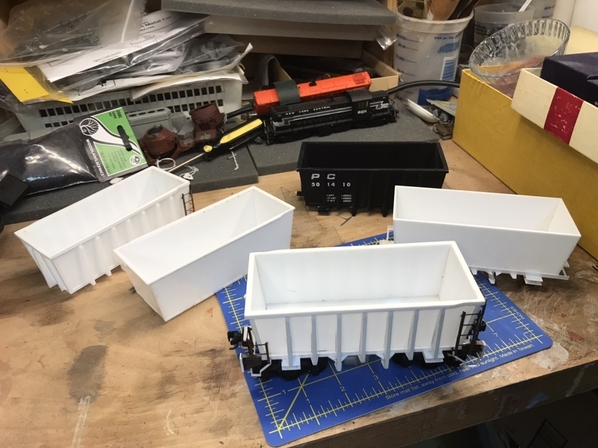
This car has been trickier to model than it appeared.   The body itself wasn’t hard, once I had a good set of drawings.  It’s basically a bathtub with ribs, no drop bottoms or hopper doors to worry about.   As they say, the devil is in the details.  The corner ladders/pusher bumpers/steps have been the hardest to resolve, and not totally there yet.   There are two different types of assemblies overall, mounted to angled car sides and each other.  Because I will be mass producing these (for myself), I need the parts to be fairly idiot proof.  Right now they involve gluing up super thin pieces of .020 polybacker at right angles with ACC.  Giant hands, super glue, and small parts aren’t a good combination.  I can do it, but it’s tedious, and I’m experimenting with another method.  I’m on V5.0 of this car right now - see below photo - and it will likely enter service, but V6.0 will be a slightly improved version, from an assembly standpoint.

F040F37F-E114-4853-A299-0BB72D186263

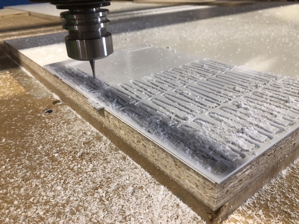
My other rivet counting OCD issue, was the ribs.  If you have been following along, the initial versions of the ribs were made from 1/8” acrylic, after an attempt to cut .080 styrene on the laser cutter resulted in too much distortion and curling with the thick styrene.  The acrylic cuts nicely, but the .125 thick ribs just looked slightly too thick, compared to the prototype.  There was some research needed to determine the actual size of these ribs, and since they were slightly tapered from the outer edge back to the hopper side, my best estimate was anything in the .080-.100 range would look better.  I couldn’t find acrylic in either of those sizes, well cast acrylic, that is.  You can get .080 extruded acrylic, and it will cut on the laser, but there is some sort of thermal issue and it crazes or cracks when you use the solvent glue on it.   The solution that I came up with was to use .100 styrene and cut it on the CNC machine.  I used to use the CNC for most things, but after obtaining the laser, I sort of forgot about it.   The next picture is sort of an over-kill situation - .100 styrene being cut by a 13 horsepower spindle.  

A0A09532-7490-47A3-8510-8D8BB3DCE3AA523E68C9-1E36-4CBB-8B9D-B175F986A6AF

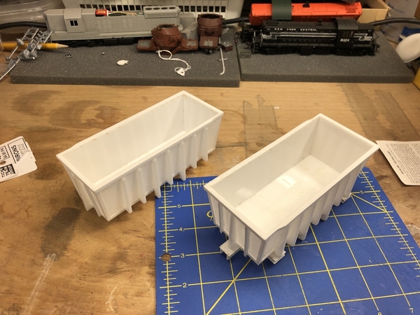
You can see by this side by side photo, the difference in the ribs is noticeable, even though we are only talking about .025” .  V1.0 on the left has the thicker .125” ribs and V5.0 on the right, the .100”.    Styrene ribs are also much easier to glue onto the acrylic sides than acrylic to acrylic.  

79DF7483-9015-403E-BC01-C9E96C28BE2F

I hope to have a completed V5.0 in the next week.  V6.0 is started.  

Attachments

Images (4)
  • F040F37F-E114-4853-A299-0BB72D186263
  • A0A09532-7490-47A3-8510-8D8BB3DCE3AA
  • 523E68C9-1E36-4CBB-8B9D-B175F986A6AF
  • 79DF7483-9015-403E-BC01-C9E96C28BE2F

Thanks John.  Chris, I did try what you suggested with the folds, but the sections are too small to fold without the polybacker breaking.    I can’t cut metals, non-ferrous or other on my CO2 laser.   Fiber lasers can cut steel and other metals.   After I posted this last night, I assembled a new version of the ladders, using acrylic, styrene, and brass wire.  It’s the winner - easier to assemble, and sturdier.  I have to dial in some of the measurements for the cut files still, and will post when I have these ladders on the car.  


Add Reply

Post

OGR Publishing, Inc., 1310 Eastside Centre Ct, Suite 6, Mountain Home, AR 72653
800-980-OGRR (6477)
www.ogaugerr.com

×
×
×
×
Link copied to your clipboard.
×
×