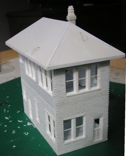
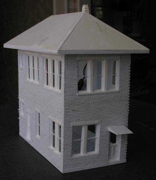
Modeling a switch tower/yard office 15-Apr-13
Background:
I grew up inNew Haven CTwhich was a junction point for passenger service betweenNew York Cityand south andBostonand Springfield Mass and north. The station had a lot of activity going on during a station stop. It was a transition point for changing from electric power to steam and or diesel power. The electric motor storage yard was on the south side of the station. In addition NH had a large postal facility so head end mail cars were frequently cut from or added too trains. In addition, the station also had a Railway Express facility adjacent to the North side of the station which involved breaking up and attaching REA cars from the front end of trains. On most trains fromBostonto NY additional coaches were added to the rear of the train depending on ticket sales.. Another operation that took place was that trains from Springfield Mass had cars taken from them that would be added to aNew Yorkbound train. New Havenhad a good size coach yard.
When I was in high school theNew Havenhad a large number of switch towers along the line. While I was away at college mid 60’s The New Haven area was converted to a CTC system and all of the towers in the area were closed. A new CTC tower was built on the West side of the station next to the motor dispatcher’s office. Currently all operations are controlled from Grand Central Terminal.
Today with electrification toBoston, New Haven Station operations have been reduced to just another 5 minute station stop. The switch tower and motor storage are gone and the area has been converted to a parking lot.
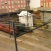
I still have to continue to reinstalled new catenary thought the station area in the foreground. However while I still have ‘easier access to the back corner’ I want to create a combination switch tower in the wedge area between the GG1 and the NH EP5. It will have the tower on the 2nd floor and the motor storage dispatcher’s office on the ground floor.
In a Carston book ‘Locomotive Terminals & Railroad Structures’ pgs 104-105 are photos and plans for a brick Illinois Central tower located in New Orleans, LA. I liked the architecture and its size and window configuration could easily be modified for my purposes.
Construction:
Step 1
The following is a description of the construction process I use. My starting point on all building modeling is creating the windows. I find this the most time consuming task in building construction since I prefer to model the actual window rather than use, even an excellent commercially available window and fitting a building around them. Also in doing so I am able to help other modelers by offering different windows and door for sale on my web site. For this model I created a set of 4 windows and 3 doors. Note, only the 3 bay and 2 bay windows and 1 door were used on the prototype. I created the set to enable me and others to create any project as I have done here using this selection of windows and doors.
Also note: the windows and doors are cast with a flange on the back side so that they can be easily popped into a 1/8” side wall from the back side. For front mounting or for use with a thicker side wall simply cut or sand off the flange.
Step 2
I model my building with styrene sheet and strips. For side walls I use 1/8” (.125)” styrene I purchase in large sheets from a plastic supply outlet.
I drawing or rescaling my desired structure on heavy paper and making a paper or card stock 3d model. This has all the sides, a floor and flat roof. to provide some structure. with the edges taped into place. I set this on my layout and check for appearance. After a day or so of steering at it I make any appropriate modification as to size changes and window/door placements, and cut the individual wall panels in styrene..
Step 3
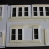
The following photos illustrate that I cut the individual wall panels from my styrene sheet. Working with each wall panel I position the windows and doors and trace the outline of the window minus the mounting flange. In this case the window opening would include the brick header and sill.
There are multiple ways to remove the window/door area from the styrene side panel. I prefer to keep the panel joint free so I first cut the outline of the cutout area. I then remove the window area by placing a 3/8” Forstner bit in my drill press and literally punching out the corners of the openings along with a row of punches leading to the center. I then return to the work bench and carefully snap out the triangular pieces on each side Lastly using my modeling knife (snap blade} I trim the edges by cutting and filing until the window/door fits snugly into the opening. This process took me approximately ½ to 1 hour for each panel.
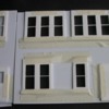
When all the panels I pop in the windows from the back and hold them in place with masking tape I do not glue the windows into place until after they are painted and glazed. I will give a good reason why further on but note the door on the back of the left panel is on the right side. After all the panels are assembled I tape then together and place them on the layout for another look. In the photo below you will notice that the door has been moved to the right front side. As originally placed it would have opened too close to the catenary pole. So all I had to do is pop out the windows, flip the panel over and re install them. In this case the problem was solved in seconds without making a new panel.
Step 4
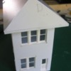
Assembling the model to have structure. Since I add interior detail to all my models by having detailed floors that slide in from the back but require structure integrity I also have structural floors that are glued into place. On this building the ground floor and second floor are add to tie 3 of the walls together. The 4th or ‘back’ wall is made to be removable. The following photo shows that I begin the second floor by placing a resting strip below the floor level around the 3 sides. I then cement the floor to both this strip and the walls. For the base floor I simply insert it into place and glue it to the walls.
I then address attaching the back wall or removable wall. As shown I add a top spacer bar to joint the side walls and 4 styrene bars on the walls at the back end. Also note I left a space between the blocks and the floor for my detail floor to slide in. The following photo shows the back wall held in place with tape. The next photo shows I used 4 small screws which I cover with Not to worry they are covered with removable signs or details and will never be seen.
Step 5
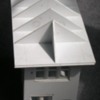
Assembling the roof. On this model the roof will be removable . I begin by creating a removable section shown below that has styrene bars that will be used to plug the roof in between 3 walls to hold the roof firm The actual roof will be created and be mounted onto the mating roof section when completed.
The next photo shows the beginning of the framing for the roof. Note I use a thick styrene plate for the base of the roof and framing members so the roof will not warp or separate from the building structure of the years.
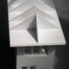
This photo shows the roof framing resting on the building.
And once again I go back to the layout and give it a test fit.
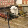
I then prepare the roof covering. However before securing the roof cover I have to install the lighting for the second floor once the roof panels are created. I also have to cut out of the roof a notch on the side where a brick chimney is placed against the wall.
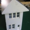
To be reported are the covering of the siding in my case with individual bricks. You may choose to use sheet siding. As I progress I will expand this write up and welcome your comments or suggestions.
Les Lewis
I may be reached at 203-226-2798 or at wsptmdlwks@gmail.com My website is


