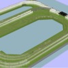
The layout is generally a 16x12 rectangle with curved corners that loops around twice. Therefore the run is roughly 56 ft around X2. So, just for the purposes of discussion lets assume 112 ft bus wire around the layout. I am using a ZW-L for power and planning a convention layout. I'm a newbie and trying to understand. I'm planning 14 ga wire for the bus, and 18 ga feeders. With that said... does that sound right? If I have 18 volts or so going around the bus with say 10-12 amps full load... do the feeders have to be 14 ga also? OR, does the voltage split and reduce by the number of feeders? ie: if 20 volts/10 amps travel around and up 4 feeders (just for simple math) does that mean the feeders only carry 5 volts/2.5 amps each, thus allowing the smaller feeder wires? I hope I'm explaining my question correctly.
Replies sorted oldest to newest
Also, since it's a double loop, is it ok to have one 56 ft bus wire around with feeders going to both loops, so I don't need to loop the bus around twice? Seems like it should be.
The voltage does not split or get reduced (except for resistance drops). The current will flow thru whichever 18ga feeder it needs to since the engine is near it. I think your wiring is probably ok, use at least 4 feeders spaced on each loop.
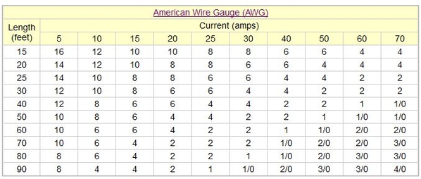
The chart I'm reading says the 14 ga can handle 15 amps, bu the 18 ga can only handle 8 amps. Is that ok? I thought the ZW-L does up to 10 amps per channel. I don't want to create an unsafe situation.
That chart is for 120vac 100 foot runs. You would have to consider the resistance of the run and the actual current and compute the voltage drop. And the allowable percentage drop you decide is ok.
That chart is referring to 110/220 volt house circuits. For example, 20 amp circuits require 12 ga wire and 30 amp circuits require 10 ga wire.
Thanks Jack, I'm glad you are following my thought pattern. I'm lost on figuring the resistance and voltage drop. Does that mean I need 12 bus/16 feeder. Or, 14 bus/ 18 feeder. I just want to be sure I'm safe.
Wire size is based on the amperage it is expected to carry, not voltage. There are charts and calculators on line to help with sizing based on distance and amperage.
If your run distances are correct I mostly agree with your choice of 14 ga. bus with 18 ga. feeders. I would probably use 12 ga. and keep the feeders under 3' in length. But I'm having a hard time understanding why a 16 x 12 would need that much wire. Do you really need to run wire following the track around both loops? Do you intend to use command control or just conventional?
Dan,
That was one of my questions above, Do I need to run the bus around the layout twice because the loop goes around twice? Or, one loop Bus with feeders going around with it up to both loops? For clarity, the main line track goes around the layout twice in a double loop. Im thinking one bus, but two sets of feeders going up to the track. Why would they need to be up to 3' long, I was guessing less that 12" for a feeder. I'm guessing max amp draw would be 10?
One buss around of 14ga and 12 inch 18ga feeders sounds fine. The thing is that you probably won’t run more than 2 engines ata time, so the current draw will only be a few amps.
Again, those wire tables are calculated for an allowable voltage drop for 120vac building wiring for a 100 foot run. Our 18 vac is a different story completely, shorter runs, but while a few volts drop is ok for a 120vac circuit, it’s too much for an 18vac run.
The best you can do without doing the math is to use the recommended gauges and lengths that have worked for other layouts on the forum. You should do fine with a buss of 14 ga and 18 ga short feeders.
@Hp289 posted:Dan,
That was one of my questions above, Do I need to run the bus around the layout twice because the loop goes around twice? Or, one loop Bus with feeders going around with it up to both loops? For clarity, the main line track goes around the layout twice in a double loop. Im thinking one bus, but two sets of feeders going up to the track. Why would they need to be up to 3' long, I was guessing less that 12" for a feeder. I'm guessing max amp draw would be 10?
How you run the bus wire depends on where the source will be located, and the buss doesn't have to follow the track in a loop. For example, if I assume your amp(s) are along one of the 16' sides you could run the buss as two separate wires, one to each back corner with leads off of each. So your buss wire has dropped from 50-something feet to about 1/2 of that. Even if you keep the same 14 or 12 ga wire you have increased the efficiency of the buss to provide current to the leads.
Note: I mentioned keeping the 18 ga. leads 3' or less.
A 10 amp maximum possible draw is a reasonable assumption and what you should size for, but what really happens in operation depends on how many engines and accessories are in the circuit. If two engines are running there may be less than 5 amps being drawn in normal operation. So two engines pulling from the same 3' lead would only see about 1/4 volt drop, and they would see about 1/2 volt drop if pulling the full 10 amps. Obviously a lead shorter than 3' will result in less voltage drop.
If you ever want to see the effect distance has on resistance check out the wiring of an electric stove. Coming from your service panel you will have finger sized cable all the way to the stove terminals.
Then from the stove terminal block to the controller and burner there are tiny spaghetti strands running a very short span.
I find these charts to be kinda helpful but not really. When watching my train's performance I can tell when it leaves a 14 ga supplied home run and enters a 12 ga home run. Or when it leaves a close 14 ga home run then runs onto the next 14 ga home run which has a longer run. On paper it should be well within range, however actual performance says otherwise.
Just because your trains run does not mean they are running at their best.
In my experience, go big or go R/C.
Attachments
To me the big concern is voltage drop, 14ga wire simply has less voltage drop over distance than a smaller diameter. If you are wiring conventional are you wiring for single train running (no blocks) so you can use a single bus? Normally with block wiring you would wire from the A handle and B handle posts, and those would feed 2 inputs of a toggle switch of a toggle switch, then the output would go to a specific block , allowing selection (with a ZW-L you could theoretically have 4 selections per block). I supposed the output wire to each block could be considered a buss wire.
Given the size of your layout and the runs, 14 gauge should be plenty for the power distribution/buss line. I would keep the feeder wire run as short as possible, given that you only run 1 engine/block at any given time, 18 gauge would be fine as a feeder IMO.
I agree, Tom. Where I buy wire it is 10 cents per foot difference between 14 and 12ga so why not get as much potential out near the track as possible with the larger buss wire.
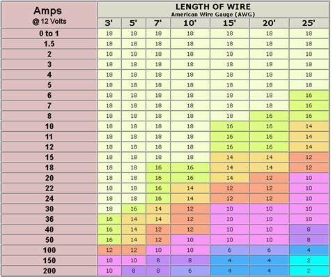
The voltage drop calculators allow you to vary the voltage. I like the 12-volt charts as a guide when used conservatively since the lower wattage is closer to what we see with model trains at 18-20vac.
Attachments
So what I'm hearing is 12ga bus would be better, but isn't really needed based on my layout size, right? If I did go up to 12 bus, are the feeders still 18ga, or do they have to go to 16ga? I"m told 16 is tough to solder to the rail sides compared to 18.
Turkey, you said run two bus wires one in each direction to split the run. Sounds like a good idea, but what terminates the wire at the end? I thought it HAD to make a loop back to the transformer? Sorry, for the newbie questions. This is my first RR build and I'm trying to do it right. I'm grateful for the assistance.
I'm attaching the track plan for further clarity.
@Hp289 posted:So what I'm hearing is 12ga bus would be better, but isn't really needed based on my layout size, right? If I did go up to 12 bus, are the feeders still 18ga, or do they have to go to 16ga? I"m told 16 is tough to solder to the rail sides compared to 18.
Turkey, you said run two bus wires one in each direction to split the run. Sounds like a good idea, but what terminates the wire at the end? I thought it HAD to make a loop back to the transformer? Sorry, for the newbie questions. This is my first RR build and I'm trying to do it right. I'm grateful for the assistance.
I'm attaching the track plan for further clarity.
Nice looking plan. Is that the power supply location on the far right?
If it were me I'd go with 12 ga buss wire, you're layout is large enough. The feeders can be 18 ga. for the very reason you mentioned, easier to work with.
If you stop and think about it for a moment you will realize that it is an engine on the track that completes the electrical loop back to the transformer. Track is part of the wiring. In theory we only need one pair of connections to the track but the reality is that we need multiple connections from the track to the transformer because the track is not a good "wire". My preference is to add feeders in pairs, so I run both buss wires out to each feeder location and install a small terminal block. But I am also wiring with considerations for using MTH Digital Command Control so I'll try not to mix any extra steps for that purpose in unless you plan to use DCS.
You have a natural split in your loops at the tilt bridge on the left so running a pair of buss wires to either side might make sense, there are still particulars I don't know.
@turkey_hollow_rr posted:In theory we only need one pair of connections to the track but the reality is that we need multiple connections from the track to the transformer because the track is not a good "wire".
Dan,
Agreed and very well said.
Mike
Guys,
Possibly a simple wiring sketch (by hand) would assist in clarifying what you are trying to convey regarding the split. I'm trying to make sense of what is being said as well as I can't picture the great suggestions being offered, though I understand the concept.
Thx gents. So, the black "thing" to the right is a small 18" bridge since that track is at 6" elevation along that wall, not the transformer. Since I plan to sit in an elevated stool in the center. The inner two tracks are at 0 elevation. By the walk through on the left, all 4 tracks are at 2" elevation. It's basically two individual, but parallel tracks, that both run a double loop next to each other. I will for now be running conventional from a new ZW-L. I will run accessories from separate power from another couple of postwar transformers I have. So for now, let's please just figure out the two tracks and trains. IF IF IF I ever go digital, I'm sure I would go Legacy and stay with Lionel. That is why I chose a bus system instead of star type wiring. But I read everything I find online, but I have no real world experience building a layout, so I'm just trying to be "sure" as best I can. I was planning to use suitcase and Wago style connectors like some of the gents talked about in another thread. I just need a little more help nailing this diagram down.
My pappy always said: "There is more than one way to skin a cat".
18 ga. with 14 or 12 ga. busses are kind of a norm. However because we do not know what we may want to do in the future you may want to consider wiring for MTH DCS which is home run or star wiring. Some say they do not need that for DCS however many do say it is needed. Barry's book is like a code book. Use it to be safe.
I had one client pre purchase 12 reels of solid core 14 ga. wire before he called me. One reel of each color.
Left with that dilemma I got out my drill motor and twisted up a quanitity of runs. No buss all direct block connections.
Not using drops but poking the wire end up through the plywood and tie I flattened a 90 degree spike head on the wire end and soldered to the rail:
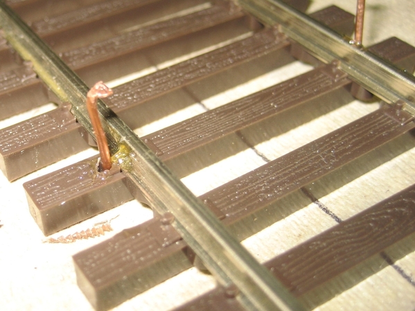 14 ga. on code .148" 2 rail Atlas
Attachments
@Mellow Hudson Mike posted:Dan,
Agreed and very well said.
Mike
Thanks Mike. I'm coherent 'til the coffee wears off.
@Allegheny posted:Guys,
Possibly a simple wiring sketch (by hand) would assist in clarifying what you are trying to convey regarding the split. I'm trying to make sense of what is being said as well as I can't picture the great suggestions being offered, though I understand the concept.
Kazar, we really haven't gone much further than discussing the advantage of individual buss runs versus a buss loop around the layout. If you understand that we can get more potential, voltage, out to the track with multiple shorter runs versus one long run then you're keeping up fine.
Pointing out the lift bridge is the first step from concepts to application. Because there have to be physical breaks in the track for the lift bridge to work there are no loops in the layout, and we have to get power to those tracks isolated on the lift bridge. Probably from the hinged side. That's one pair of bus wires out to a terminal strip close to the hinge. That buss pair can feed several drops to the track as well as the bridge. Again, my personal preference is not to try to use that bridge track as part of the wiring to feed track on the opposite side so I would run a second buss pair down to the opposite of the hinge side.
This is buss wiring in general. Depending on track, power supply, number of engines running at once, etc, it may be wise to have two sets of buss pairs on either side of the layout.
Tom, as stated, IF I ever go digital it will be Legacy not MTH. For now, I'm conventional. I think your wire spike practice is first class. Probably more than I'm going to do. This isn't going to be very fancy.
I expect to run one engine per track at any given time with unusual exception to run two.
I was figuring one main buss per track, with probably a feeder every 10ft or so. 14/18 or 12/18. From the ZW-L. Two outside handles.
I had also figured another bus for switches and the bridge. From the ZW-L. Maybe one of the inside handles?
Another, from a separate postwar transformer for accessories only.
Sorta, like this Primitive sketch?

Attachments
" ie: if 20 volts/10 amps travel around and up 4 feeders (just for simple math) does that mean the feeders only carry 5 volts/2.5 amps each, thus allowing the smaller feeder wires?"
No, full voltage is carried by all feeders, and the amperage is all through the feeder(s) where trainsare drawing power. On my 35x16 layout all wires, from transformer, thru TIUs and control panel, all the way to track, ar 14 gauge
@Hp289 posted:Thx gents. So, the black "thing" to the right is a small 18" bridge since that track is at 6" elevation along that wall, not the transformer. Since I plan to sit in an elevated stool in the center. The inner two tracks are at 0 elevation. By the walk through on the left, all 4 tracks are at 2" elevation. It's basically two individual, but parallel tracks, that both run a double loop next to each other. I will for now be running conventional from a new ZW-L. I will run accessories from separate power from another couple of postwar transformers I have. So for now, let's please just figure out the two tracks and trains. IF IF IF I ever go digital, I'm sure I would go Legacy and stay with Lionel. That is why I chose a bus system instead of star type wiring. But I read everything I find online, but I have no real world experience building a layout, so I'm just trying to be "sure" as best I can. I was planning to use suitcase and Wago style connectors like some of the gents talked about in another thread. I just need a little more help nailing this diagram down.
Wagos work well. If I mention terminal strip, you substitute wago. But you may want
Legacy or DCS, either way you would be running more trains and require more power to the track. It is much easier to wire for that possibility now. That's part of why I suggest two buss pairs on either side for the main loops. I would also suggest a buss pair to each of the yard and upper level siding, you may want to cut power to them at some point in the future.
So you have the ZWL, two buss pairs on the top half, two buss pairs on the bottom half, a buss pair to the yard and a buss pair to the upper level siding. My approach would be to start with a single feeder pair from each buss first and see how things work. If your feeds are several feet down the track perhaps some of the buss wires don't have to run all the way across the layout, but one needs to get close enough to service the lift.
This wiring will run conventional, Legacy, is about 90% of the recommended way to run DCS. That last little bit are the blocks @bigkid mentioned. Those track blocks can also be beneficial to conventional power distribution but not necessary.
One think that hasn't been mentioned I don't think is the quality of the wire. There is a lot of copper clad aluminum wire that I think is sold as audio or speaker wire. A 12 ga wire of this is really more like 15 ga or so for power because of the resistance of the aluminum which is double that of 100% copper. Also you can tell what kind of wire it is by the price. Copper clad aluminum usually sells for about 20% of the cost of 100% copper. I bought the red/black zip wire which is good for power buss wiring. All Electronics sells 100% copper which they assured me when I asked. 12ga is now about a dollar a foot. Probably up from a couple years ago after all the shortages we have been suffering the last two years.
Shop around. But be sure what you're getting.
Jack, I read that previously and plan to buy all copper. Turkey, you lost me. Sorry. The Gent who has been helping with the plan also gave me this as a guide of where to put the insulating pins. This was so I could figure out how to cut power to those sections (blocks?) since I was running conventional. Can you draw something for me, I'm still sorta lost? ...but following a little.

Attachments
@cjack posted:One think that hasn't been mentioned I don't think is the quality of the wire. There is a lot of copper clad aluminum wire that I think is sold as audio or speaker wire. A 12 ga wire of this is really more like 15 ga or so for power because of the resistance of the aluminum which is double that of 100% copper. Also you can tell what kind of wire it is by the price. Copper clad aluminum usually sells for about 20% of the cost of 100% copper. I bought the red/black zip wire which is good for power buss wiring. All Electronics sells 100% copper which they assured me when I asked. 12ga is now about a dollar a foot. Probably up from a couple years ago after all the shortages we have been suffering the last two years.
Shop around. But be sure what you're getting.
Chuck you made some very good points about the wire itself. There's a big difference running with aluminum vs. copper. I would image also the heat being rejected is another concern, but not necessarily in this application.
@Hp289 posted:Jack, I read that previously and plan to buy all copper. Turkey, you lost me. Sorry. The Gent who has been helping with the plan also gave me this as a guide of where to put the insulating pins. This was so I could figure out how to cut power to those sections (blocks?) since I was running conventional. Can you draw something for me, I'm still sorta lost? ...but following a little.
You also have cuts at the lift bridge, the same as isolating pins. This is what I was attempting to describe.
I'll try something in Paint. Where do you plan to place the ZW?
In the meantime, you can buy 12 ga stranded copper wire for about 32 cents/foot in spools of 100 feet or more. Cross-link SXL wire, Del City
I bought 500 feet of #14 stranded copper wire from Home Depot for less than $50 last year. My layout is 12 x 24, and I have no doubt that #14 was sufficient for the wiring. I have plenty of #18 drops, and I've had no issues with voltage drops, even when running two sets of double-headed steamers on the mainline, smoke and all.
Have you considered individual toggle switch controlled blocks? If you are working off just one or two power districts you can have a bugger of a time finding shorts.
I run my power into a MTH distribution terminal strip then on to a toggle on my track plan then the track. Here is a sample:If there is a short simply turn all toggles off then bring them back on one at a time and you will find the isolated problem area. No buss on this method. The more involved your layout is the more this system will help you. By default this is star wiring.
Attachments
14 ga. stranded copper SXL, 23 cents per foot, 100 feet or more. 19 1/2 cents per foot at 500 feet. I can never find anything but black at the Depot.
I strongly recommend breaking up the main lines into blocks, each controlled by toggle switches. When running conventional, this allows you to have several locos on the main lines as well as the sidings, and as noted above, aids in finding shorts. On my layout, built in 1991 for conventional, I have over 70 such toggle-switched blocks. All toggles are located on a control panel
@turkey_hollow_rr posted:14 ga. stranded copper SXL, 23 cents per foot, 100 feet or more. 19 1/2 cents per foot at 500 feet. I can never find anything but black at the Depot.
I bought red, black, blue, and White at HD. Price has gone up a bunch in the year since I bought mine.

Attachments
1. Just to clarify, the bus wires do not connect to anything at their ends - they simply stop wherever you want them to. Think of them like extensions of the + and - terminals on your transformer that you are simply spreading out under the layout in order to be able to supply power to the track all around the layout.
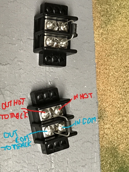
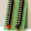
2. Personally, I like using multi-port terminal blocks like the MTH one shown below to make my track feeder and accessory connections. I think it's easier wiring (just add spade crimps) and more bullet-proof. Just run two wires from your transformer to the terminal block and then run as many pairs of feeders out to your track as you need. They come in 12 and 24 port varieties and are good if you should ever run DCS. I use them in conjunction with two-gang mini-terminal blocks at each feeder location. Note that each mini-block has a TVS suppressor soldered to it for command control protection. I run 14 ga wires from transformer to main terminal block; 16 ga wires from the main terminal block to each two-gang mini-block and then 18 ga feeder wires from each mini-block to the track.
You can add as many terminal blocks as you like and also use them to feed power to accessories, etc., as long as you don't exceed the amp draw specs.
Attachments
From strictly an electrical distribution perspective---i.e., without considering effect upon DCS or other command control signals---bringing the ends of the buss around to the source, creating a loop, improves power, effectively doubling the wire size.
I thought I was doing a bus wire main with feeders, and toggles controlling bus to the areas outside the insulation pins. ?
RJR, I thought I saw above that the ends were supposed to be terminated at the end, not looped back to transformer?
@gunrunnerjohn posted:I bought red, black, blue, and White at HD. Price has gone up a bunch in the year since I bought mine.
My local Depot is woefully under stocked on many items. But they have lots of Romex and lamp cord.


