Yes. It is certainly unforgiving. In the BP plant study I did I found that supervisors wouldn't ask hourly to do unsafe jobs, but they would do it themselves. The other big finding was there was no process for updating training manuals when something in the process changed. Without constant diligence, the manuals eventually became worthless. When I wrote about the program at Bayport, the training manager there was ruthless. Nothing slipped through the cracks, and it showed.

Today, due to some errands I had one very short hour in the shop, but did get filler set #2 almost finished. But I was rushing. When I'm rushing I make mistakes and have to do stuff over. "There's never enough time to do things right, but there's always time to do things over." At least today there was.

Bending the new one in reverse wasn't easy since not every bend was reversed. Everything went okay until I got to making and soldering together the vertical support tube. For some reason I cut the first on a good 3/16" too short. Soldered it all up and went to put it all together on the H-beam and it was way short of the end when I went to put on the bottom support. At first I didn't know what I was looking at and then realized that the whole thing was wrong. I de-soldered the tube, cut a new one and new diagonal brace (longer) and soldered it together again. I needed to be redone anyway since the first one's soldering was not up to my standards.

Then after putting it all together, and setting it up for a picture comparing it to the other one, I realized that I mounted the whole arm upside down on the H-Beam. I had to break lose a glue joint and reassemble. The picture now shows the correct position with a clamp holding the glue joint.

CT Filling Rig no-2

Tomorrow, these will be finished and mounted on the loading platform.

Attachments

Images (1)
  • CT Filling Rig no-2

With a short session again, I was able to finish up the loading rack including the lighting.

I finished up filler boom #2 and mounted both. I needed to add a spacer block at the foot of the diagonal brace and used solvent and CA to secure everything. The booms rotated freely... too freely, so I secured them in the rear position with some CA so they don't swing over the tracks.

CT Load Rack Back Brace

I made two more light posts using a smaller diameter wire since the zip cord was too fat to go through the tubing. I added a reinforcing block under the deck to provide more meat to hold the poles in place. I took advantage of the hollow tube vertical posts to fish the leads through them and out the bottom and into the layout. I used a piece of black iron wire to fish the leads. I put a slight curve in the fish wire, fed it from the hole in the bottom of the foot up to the hole in the side of the tube. By keeping the curve aligned with the hole, the fish wire popped out of the hole right on schedule.

CT Load Rack Light Post mount

With the lamps in place, all that's left is the lower lever pipe rack. That will be a quick job without any complications. (Monday).

I then took the newly completed rack to the tracks to re-check all the clearances. I won't be fastening this to the base plate until it's all painted. 

CT FIt Test Final 1CT Fit Test Final 2

I should have built the pipe rack then, but it slipped my mind. What I wanted to do since the wire fish was so successful on the rack was to do the same and mount the lights on the distillation tower. In this case, the bottom hole had to be much, much bigger so there would be any chance of having the fish finding the exit.

I'm putting lights on two levels and added the reinforcing blocks as before. I drilled a pilot, and then a large pilot and then used a fairly large drill for the bottom. This was NOT A GOOD IDEA! I originally thought about routing the hole larger. I couldn't really grab the tower to support it while drilling and took the drilling really slow. But all the while, I'm thinking... "Hmmm....What happens if that drill grabs when I gets into the plastic base plate?" So of course it did! When ever you hear that little voice of reason, you should stop and do something different because trouble is coming.

The drill grabbed and spun the tower in my hand breaking off 3 of the five downward facing piping on the surface. It snapped the fragile pipe supports right at the base and threw the pipes onto the floor. I finished up the hole by turning the chuck by hand. The hole still may not be big enough so I will end up routing it bigger anyway.

CT Dist Col Wire Exit

Here are the pipes that I will have to repair. Notice the "normal" state of my workbench. I am not a neat person.

CT Dist Col Damage Control

I will drill the stubs and install 0.020" brass wire to reinforce them. I'll get it all back together... it will just take some time. You can see one of the reinforcing blocks in this picture on the first platform. For the spherical tanks I'm using light poles that will reach all the way to the base instead of trying to mount them on the platform. There's not enough access. For the big liquids tank, I will probably go the same route. Getting closer to the finish line.

Attachments

Images (6)
  • CT Load Rack Back Brace
  • CT Load Rack Light Post mount
  • CT FIt Test Final 1
  • CT Fit Test Final 2
  • CT Dist Col Wire Exit
  • CT Dist Col Damage Control

Mark, it's like when you've sold your house, but haven't moved yet. All kinds of weird stuff starts happening when your house knows you don't love it any more. It's nerve wracking. When we moved here 8 years ago, on the day of the final inspection of our old house before closing, I went down in the basement for one more look around to make sure we got everything after the movers had left and there's water dripping onto the floor in a puddle coming from something on the first floor. I had a heart attack... 

We were taking our washer and dryers which were in an enclosure off the kitchen. The stop valves, which sat in that plastic box in the wall, hadn't been shut off for years, and the washer in the hot side no longer worked, but the drip when down inside the wall and down into the basement. We didn't have time to replace the valve, but my contractor brother in law said, just take a washer hose and connect it from one valve to the other so they would just leak into each other. 

But we had to tell the buyers at closing that there was this leak which shouldn't be a problem when a washer is hooked up. They didn't mind, which in itself was a miracle since you should see what they made us change/fix before buying the place.

Like I said... nerve wracking.

I know exactly what you mean!!  We experienced the exact same thing when shutting off the washer valves to move.  Fortunately, we moved the washer out a couple days before closing, and the valves stopped leaking.  Nifty idea your brother-in-law had.  We have had to fix a bunch of minuscule items before selling during our several moves.  The last sell, before moving to this house went smoothly!

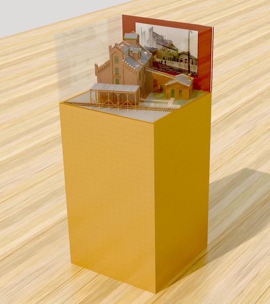
Got the Bernheim model safely delivered to Heaven Hill's Bourbon Experience Center at the Bardstown, KY headquarters. I was totally impressed with where they plan on exhibiting the model. It is dead center in the middle of the room (redundant) right over the first floor outlet as seen in this picture I took today. They waited until I delivered the model to build the show case because they wanted to be sure of the sizes. 

HH Bourbon Heritage Center 1

Here's the image I sent them today of my concept of the display. They were open to suggestions.

Bernheim Display Final

I don't know how long it will take to finish this, but the model is right not taking up space in the general manager's office so I'm sure she'll want to expedite it and get it under plexiglass.

Attachments

Images (2)
  • HH Bourbon Heritage Center 1
  • Bernheim Display Final

Thanks Pat and Mark! 

Happy Tuesday. Even though an hour's worth of elliptical and bike, I got a good two hours in the shop. First hour was spent repairing the destroyed piping around the distillation tower. I used my Drill-with-microdrill, insert-brass-wire method. I used a 0.020" carbide drill and then brass wire of the same size. The hardest part is getting the holes reasonably centered in the remnant of the broken pipe hanger and then duplicating same in the center of the piece still hanging on the pipe. 

Dist Tower Pipe Hanger repair

I did have to replace one hanger when the stub's glue broke loose and it fell inside the tower so I needed a new one. I only have one left and don't want to buy more. If I have to scratch build them I will. All of the pipes are now back in place and actually probably stronger than before.

Dist Tower Pipes Repaired

With the tower back together I got back to putting in the lighting. I made up two more lamp assemblies and drilled the reinforcing blocks on the tower platforms. This was a bit tricky, and I probably should have installed these pads before I installed the platforms on the tower. Next time... As the drill broke through it did break the pad off the platform, but it was no big deal and I reglued them when installing the light poles. Even though I was using 1/8" brass tubing, I drilled the holes .144" to enable the negative lead which is soldered on the outside of the tube bottom to fit thought the opening without using excessive force. It's all secured with medium CA.

Dist Tower Lights

Next I had to fish the cables down inside the tower so they'd be less obvious. Again I used the black iron and twisted a loop at the end to capture the thinner red wire. Getting down the tube required trial and error and persistence. All of the pipe hanger ends are protruding inside the tube so the fish wire was snagging on them and not running straight down the tube. Luckily I made the bottom hole big enough so I could peer up inside the tower and see where the fish wire was. I then made a grab hook with some brass wire and worked it up from the bottom to grab the wire and steer it to the exit. When it got close, I went in with a tweezers and pulled it out of the bottom. 

I was very happy when I drew out that black wire. 

Dist Tower Fist Wire

The negative lead is masking taped to the red one and then carefully coaxing this fat portion through the top opening. The next part to coax is the shrink-tubed upper portions if there are any. 

Dist Tower Wires Fished

The lower light's wires were easier since the fish didn't have to travel as far and couldn't get itself into as much trouble. In this case, as soon as it was near I snagged the fish with the tweezers and pulled everything through. I checked all the lights with my LED tester rig and they both worked and the tower's ready for paint. Running the lights like this was, while a bit finicky, worked out as I envisioned it.

I glued lamp blocks onto the multi-tank platform and the stair platform for the large liquid tank in anticipation of their light installation. I started making two more light posts, but ran out of time. Tomorrow's a full afternoon session and I'll get more lighting done. I'm trying to get as much done as possible before the guests come in a week and half, but I may not make it. I know, I know, you've all said that I have a lot to show them anyway, but it's not as satisfying.

Attachments

Images (5)
  • Dist Tower Pipe Hanger repair
  • Dist Tower Pipes Repaired
  • Dist Tower Lights
  • Dist Tower Fist Wire
  • Dist Tower Wires Fished

Lights, lights and more lights. 

Decided to run the lighting power for the big tank through the tank itself like I did with the distillation tower. I used the Dremel to open up a nice sized hole in the base to fish the wires. I was able to capture them with a long tweezers and didn't need a separate fish wire.

Refinery Big Tank Lighting 2

Topside, I CA'd the light into the hole drilled through the reinforcing block I added yesterday and then, before feeding the wire through the tank, added a piece of shrink tubing to help conceal (a bit) the wire as it turns inwards. I'm sure this is a prototypical no-no, but the conduit that would have been on the real tank is so small in 1:48 that it wouldn't carry any wires. The 1/8" tubing for the lights may be a bit heavy (6 scale inches), but it's the only size that will work for me with the kinds of LEDs I'm using. If I was using the type that some use with the magnet wire leads, smaller tubing would work.
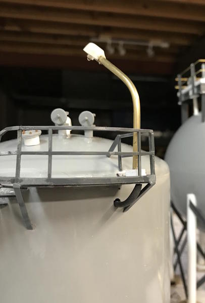
Refinery Big Tank Lighting 1

I also did a similar thing bringing the wires down through a leg on the multi-tank platform.

Refinery Ops Platform Light

From the viewing distance, these wire tricks will be very hard to see. 

I then added two lights to the roof of the cooling tower. Again, I first reinforced the mounting points by adding thick stuff underneath. I drilled corresponding holes in the bottom of the CT box and then, using a transfer punch, located the same holes in the Masonite base which the wires will pass through to the layout's nether regions.
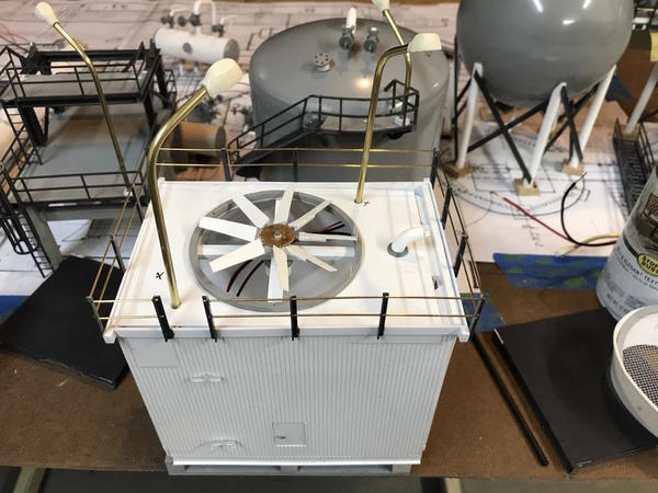
CT Lighting

After looking at this picture, I suddenly realized that I positioned these lights from underneath basically paying attention to interference with internal structures, totally ignoring the topsides problems which may occur. I ran downstairs while writing all this and put the venturi on to see if it cleared the poles. Whew! It does. Barely. As Mark Knopfler sings, "You get lucky sometimes."
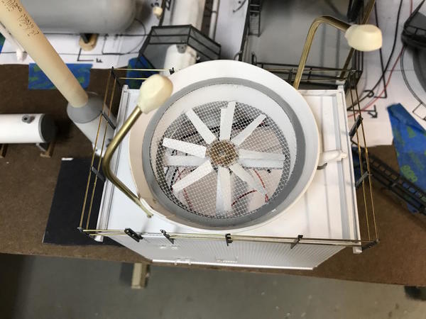
CT Light-venturi fit

With the cooling tower lit, all the unit mounted lighting is done. I still had some surface mounted fixtures to build. I figured six more will do the trick. As it is, this thing is going to light up like an amusement park. I'm mass producing this batch. I pre-bent all the LEDs, pre-bent all the tubes, drilled the negative lead hole in the bottom end after sanding a flat spot to facilitate drilling, and soldered them all up.
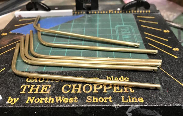
Refinery All the Lights 2

I thought I show a closeup of the LED soldering even if I show it a long time ago when building the Substation or the silo system, since it's something that folks might like to reproduce for themselves. After wrapping the + Lead around the + LED lead, soldering it and then putting small shrink tubing around it to isolate it from the tube (which is the negative lead), I carefully wrap the negative LED lead over the tube's bottom, again supporting the lead between the bend and the head. I need to keep the tube top clear since the light hood gets glued there. I use a little bit of extra rosin flux to promote adhesion and using the Weller iron with a broad tip and temperature set a 3+, I solder the lead to the tube by heating the tube to get the solder to flow. You should be able to see the contour of the conductor under the solder. The solder flow should be concave, not convex. Convex indicates bad adhesion with the solder's surface tension is causing it to ball up. Usually this means not enough heat on the substrate or unclean surfaces.

Remember: Don't bend LED leads at the head. If you do, the stress will kill the LED. Hold long nose pliers under the head and bend away from the pliers. Always!

Refinery Lighting LED install

Here are all six new lights waiting for the guy who's casting the resin parts to get his act together.

And sometimes you don't get lucky... While doing all this, I wrecked several LEDs. First, I test the LEDs before soldering anything. Then I test the fixture again when all the wiring is done, but before the hood is CA'd on. Remember, the pole is negative. I have a test rig that is 12VDC with a positive lead and two negatives; one with a 470 ohm current limiting resistor and one straight through. If I testing the lighting installed in a structure it will have its own current limiter so I could run straight 12 VDC. I had the positive lead on the + power, and accidentally brushed the tube over the un-protected negative. The LED lit....ONCE, and then it was gone. I desoldered it and replaced it. 

Then I couldn't find the bag of LEDs that was supposed to be right in front of me on the workbench. I looked all over the place. Then I see it. Behind me... rolled over by my chair caster. Several were deformed, and one I tested was kaput. Murphy's law at work.
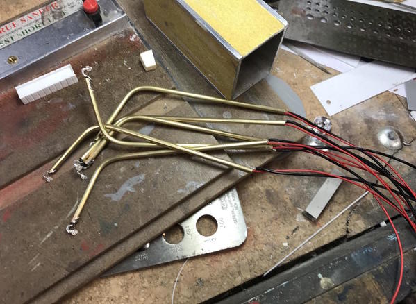
Refinery All the Lights

For the ground mounted fixtures I have a resin mold of a faux concrete base. I've also shown this before, but it bears repeating. Since this is a tapered part and needs a square-flat bottom, I made a sanding fixture that supports the part at the correct position vertically and horizontally so I can sand the bottom with the Precision Sander.
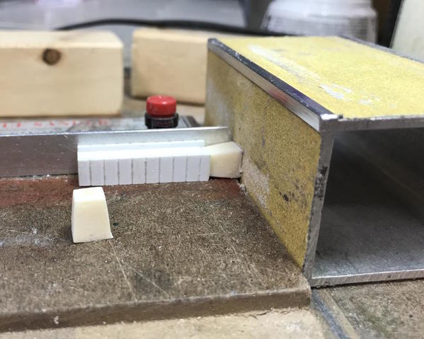
Lighting Feet Sanding Rig

I cast a dimple into the top so drilling would be easy. But I also needed a jig to hold it square on the table. A vise was too strong and would damage the fragile resin. This hole goes clean through. The fixture's hole is just a tad smaller than the overall size of the base so the base sits tightly when inserted from underneath the jig. All this means that I can reproduce these parts over and over.
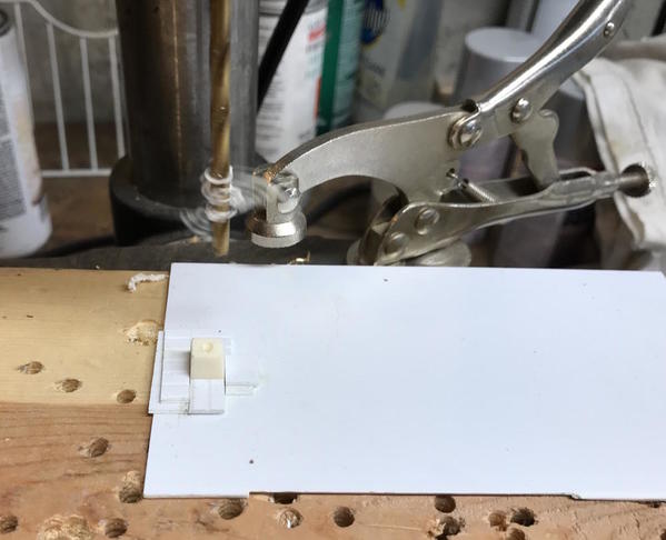
Lighting Feet Drill Rig

Lighting will be done as soon as I can cast the remaining parts. Then it's on to the pipe racks and hangers. That means sometime next week it all goes to the paint shop. Then I have to build the ops building and all that fencing so it clearly won't all be finished when I wanted to, but it will be quite far along.

I need to buy more caged ladders to go to the top of the flare tower. I also want to put the flashing lights on top which should another tricky fishing expedition.

Attachments

Images (10)
  • Refinery Big Tank Lighting 2
  • Refinery Big Tank Lighting 1
  • Refinery Ops Platform Light
  • CT Lighting
  • Refinery All the Lights 2
  • Refinery Lighting LED install
  • Refinery All the Lights
  • Lighting Feet Sanding Rig
  • Lighting Feet Drill Rig
  • CT Light-venturi fit
Last edited by Trainman2001

Thanks Jesse!

Worked three hours today (and did some exercising too) and while made progress, it doesn't look like much. However, it was important stuff.

Throughout the day I molded the remaining light head and bases. It takes roughly 1/2 hour per pour for the resin to cure enough to pull from the mold without too much distortion. It's still quite rubbery and hardens over the next couple of hours. If I try to sand them too soon they don't really sand well and they can be deformed. It's best to wait... there's my lack of patience rearing its ugly head again.

Again, Plastruct short-changed the quantity of 16" (scale) H-beam to make the amount of pipe rack supports shown on the plot plan. They show 8 on the plan and I only had enough to make 5, and that was with reducing the rack's width from 8" to 5" so I could get enough cross pieces out of the stock. It's a simple assembly with two verticals and a lintel across the top. I cut them all in the miter box and then squared their ends on the Precision Sander. I glued them with solvent cement on the surface plate using the angle blocks to keep squareness.

The feet are pieces of plywood cut into 5/8" squares, sanded and epoxied to the H-beams. I thought about putting a mounting plate on the bottoms and some NBWs, but I decided to just assume that the H-beams were embedded in the concrete when it was poured. It's not as critical as a unit op. That's my take on the matter. The single post is to hold the piping coming to and from the heater.

Refinery Pipe Racks

I also cut and glued plywood bases for under all the pump units too. I needed to get this done since it affects the piping scheme running to them.

I placed the racks on the plan to see how five looked instead of the eight needed. It will be okay, but does weaken the piping system. I still would like someone to tell me why the plans show the pipes running the full length of the piping system with connections running to them using T's. I don't know what you'd want many linear feet of piping containing product that would not be flowing anywhere. Now I have to figure out how and when to paint and get all this stuff together and onto the layout. I supposed all the piping could be painted en-masse before installation. I want some of the piping to be other than white... most likely metallic since most of the pipes are jacketed. I may glue the piping onto the entire rack system before mounting, but this seems like it would be ridiculously flimsy and hard to handle. I need some input from our refinery builders. Al... do you hear me?

Refinery Pipe Racks Fitting

The chain link fence will be made in sections with the Brennan fixture and installed in panels onto the layout itself. I still have to build the ops building. At first I was thinking about some kind of brick structure, but many of the buildings occupying the chem plants on the Gulf Coast are simple curtain wall structures. I could use the same corrugated siding as I used for the cooling tower and then add a standing seam roof. I have the roofing material, but will be some more siding.

Attachments

Images (2)
  • Refinery Pipe Racks
  • Refinery Pipe Racks Fitting

Glad to please! 

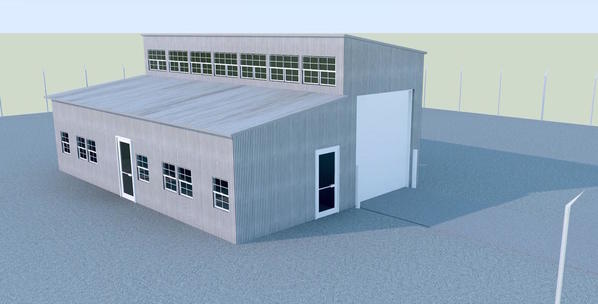
Trip to the LHS today to pick up ladder stock for the flare tower and some more corrugated siding for the future ops building. Speaking of ops building, I drew something up last night on SketchUp. I figured the space at about 10" X 7" (40' X 28' in O'scale). Not a big building, but enough to make an impression that it's a working establishment.

Ops Building

It's not based on any specific prototype, but I needed office and service space in this small footprint. I reckoned that there would be a high-bay area and a normal space, thus the two-tier design. I'm not sure about the upper windows, not from a design standpoint, but from what kind I'm going to be able to find. I ordered some Grandt Line windows at the hobby shop since they get them and I don't have to pay for shipping. It will have corrugated walls and standing seam metal roofing. I'll scratch-built the overhead door. It looks like the O.H. door is going to face the wall so I'm won't worry about having it open or doing the interior, unless I put one on each end. hmmmmm...

When I got back to the shop I cleaned up the resin castings.

Lights Heads and Bases

I added all these to the lights I built yesterday and with that, completed all the lighting for the site. There will be 16 LED lights illuminating the refinery itself. I will also have to light the ops building and the drive at the door. So I'll have to make some more now that I'm thinking about it. Luckily, I've got the whole deal down to a process that's easy to replicate.

I wanted to make some pipe supports that would go on top of the pipe racks. The print calls for five small diameter pipes and one large lying in the middle. I use 0.030" X .125" Evergreen stock. I scribed a line lengthwise which would be the split line and then laid out the hole positions with a divider. I then drilled the holes. The large pipe is also .125" so I quickly realized that I couldn't drill the hole since it will split the piece in two. So I cut the piece in two.

Refinery Pipe Supports 1

I first was cutting the segment of 1/4" hole with an Xacto, but in the last batch realized that I could punch it out with the 1/4" hollow punch. I scribed a centerline down the pipe rack top as a gluing guide and glued the segments in position.

Refinery Pipe Supports 2

As I was gluing them up, I somehow ran short of the piece with the two holes. One side has three pipes and the other two. So I made some more. Then I looked at this picture... And there are two pieces with two holes. DOH! I will form the missing hole with the Dremel. When I placed all five back on the plans I realized that in some places there are more than five pipes and in other less. I figure this out later. I still don't understand why the large pipe from the distillation tower to the reflux drum runs the entire length of the site with Ts coming off to the two units. I'll built it like it shows, but I don't understand it. You can see this line as the double line running the length of the plan.

Refinery Pipe Supports 3

I'm still deciding on the equipment positions. I may be able to run them perpendicular as originally shown on the plans which would free up space on the left for the ops building and some parking area. 

Since I bought the ladders for the flare, I started working on that again. I think it will need two platforms; one in the middle and one at the top. I started building the platforms. This time I'm using styrene. I may revert back to ABS. The styrene has a bunch of residual spray adhesive from other work I did with it. I'll remove it with GooGone. 

Refinery Flare Platform 1

This upper platform will not be 100% circular. There needs to be space to the ladder to enter the platform. I'm going to build a styrene frame around it and probably do my Make-it-yourself-railing scheme, since the radius is pretty tight and I won't get a commercial railing to make the curve. With the brass wire I can pre-bend the curve and thread it around. The outer frame with serve several purposes: strengthen the assembly, provide anchorage for the rail stanchions and give me a place to add the flashing LED warning lights. I have bright blue white or red. Strobes are more modern, but flashing red might look cooler. Perhaps both?

I may get one more work day next week, then lots of family and friends converge on Louisville for my younger grandson's Bar Mitzvah. Like 3 years ago, I'm hoping that folks will be able to see the progress on the railroad. Lots! The week after will be more normal.


Attachments

Images (6)
  • Ops Building
  • Lights Heads and Bases
  • Refinery Pipe Supports 1
  • Refinery Pipe Supports 2
  • Refinery Pipe Supports 3
  • Refinery Flare Platform 1

A couple of hours work on the flare. I got the platforms roughed out and fitted the ladders. The total height is 23.5" high so it's approaching 100 scale feet. Big for my layout, but puny in real life.

I shot myself in the foot wiring-wise when I filled the lower chamber with lead shot and then glued it all together with CA. It was an idea to add more weight to the bottom and help stabilize it since it's so top heavy. But... it now means that I can't run the light wiring out of the bottom. If I attempt to run the wires out the side it'll make fishing the wires much more difficult.

I made the platforms out of very thin stuff and put on a double edge of 0.020" Evergreen stock. It's springy so I had to coax it around and use both solvent and CA to get it to stay there.

Refinery Flare Platform Edging

Underneath I added the triangular braces that support it on the column. The column in this case is CPVC potable water pipe and is impervious to standard solvent cement so I'll secure everything with CA. I have put the capping on that I did on the distillation tower and will do that tomorrow. I ordered styrene railing and will permanently install the platforms when the railings are installed... next week.

Refinery Flare Platform Details

I only had 6 Plastruct ladder supports left so I used four on the lower ladder and 2 on the upper. There's really nothing that's going to disturb the ladders once it's on the layout. I put a mid platform halfway up the tower, but frankly don't know how far up the ladder should go before there's a rest platform. I'm sure someone out there knows this fact and could share it with me.

Refinery Flare Ladder Fitting

There's a sneaky way that I can run the wires from the warning lights at the top. I have to run a couple of pipes from the bottom to the top, one for 'steam' and one for 'pilot gas' to the pilot light. I can't get both conductors down one Plastruct #4 pipe, but I can get the positive down one and the negative down the other. I have no more Plastruct pipe hangers so I'll have to scratch build some. I can us some brass tubing with a 1/8" i.d. and a piece of brass rod soldered to it. It will take some time, but so will ordering them via Internet and waiting a week till they arrive.

Attachments

Images (3)
  • Refinery Flare Platform Edging
  • Refinery Flare Platform Details
  • Refinery Flare Ladder Fitting

Thank you Eddie! But as they say on the all the infomercials; "But wait, there's more!"

This post actually started 6 pages before the one you read where I describe the preparation of the space, benchwork, track laying and wiring. It's here: https://ogrforum.ogaugerr.com/...-build-thread?page=1

I did that original thread in the layout design and construction forum and then moved over the Scenery and Structures forum when I started doing landscaping and all the buildings.

If you read 48 pages, another six is a piece of cake. Let me know how you make out on this thread. That thread is no longer being supported (for some reason).

Myles,   In reference to the question you asked a couple posts back, OSHA Standard 29 CFR Part 1910, Subpart D - Walking-Working Surfaces, 1910.27 Fixed Ladders (a) Design requirements (2) Landing platforms..."landing platforms shall be provided for each 30 feet of height or fraction thereof..."    Cages are required for any ladder more than 20 feet high; the maximum of 30 feet is also measured differently for the type of egress to platform utilized; reference drawings 1910.27, figure D-8.

Also, in the petro-chem plants I worked, rack piping was very often color coded painted per product carried by the pipes.  Example: cooling water was light blue; process water dark blue; natural gas orange; product gases were often multi color striped per unit's criteria; cyanide was always identified with purple.  This was always in association with affixed labels and marking on the pipe or jacketing itself, and facing downward for easy identification from the ground as a pipe was "walked down" for inspections.  You could not always rely on size of pipe and labeling/marking.  In one unit, during sub-zero weather, a flowing process line froze up and expanded, without bursting.  We were walking it down to identify the impacted area to remove/replace as necessary.  Now, mind you, this was a heated flowing process product line.  However, the 4 inch painted line we were looking for had swollen to almost 6 inches and the paint code color had flaked off in the process of expansion.  Only by referring to the unit model in the control room, and a lot of extra walking/climbing in the racks, could we positively identify the frozen and grossly expanded line. Any day this would be a chore in a chemical plant.  This was in the middle of January, after midnight, winds out of the North and temps below freezing, wind chills below zero.  But, we found and removed/replaced the damaged pipe as needed before Noon the next day, a total of approx. 90 ft to 110 ft pipe.  Hardest part, besides the chill factor, was removing the old pipe and wrestling the new up and through the already crowded pipe rack.  Of course, it had to be in the middle rack of a 3 tier pipe rack.  

Sometimes it is something, almost say amazing, how memories of events can come forward when prodded just right.  My wife has all but disallowed me to speak of some things I remember when working in that environment.  But, it wasn't all dangerous and I really did enjoy the satisfaction it gave, and going home at the end of the day, however long it may turn out to be.

Jesse    TCA    12-68275 

Jesse, based on your new information (thank you), my spacing is probably too long. I'm running at 11 inches between platforms which is 44 real feet... to long. I could adjust this by making another platform and re-sectioning the ladders.

I've also sent a note on the tech forum to reinstate the thread based on RTR's input. Again... thanks!

Haircut day so not much time. I've decided that I'm definitely going to do the run-the-wiring-through-the-external-piping scheme. In preparation for that I had to create my own pipe hangers.

I didn't have a brass tube with the exact o.d. for the 1/8" Plastruct tubes, but it was close enough. The process is as follows:

  1. File a flat spot on the tubing so the micro-center punch doesn't skitter off. 
  2. Drill pilot hole with 0.032" carbide drill in pin vise
  3. Open hole to a #51 drill which is a nice tight fit for a 1/16" d. piece of brass rod
  4. Apply a bit of rosin flux to the assembly and solder. First I tried using the RSU, but in this instance, the Weller iron with broad tip actually worked better.
  5. Using the micro saw, slice off the correct amount of tubing, about 1/8"
  6. Again with micro saw, slice the tubing approximately in half
  7. Using flexishaft Dremel and diamond burr, grind off any remaining stub of the rod protruding into the cavity.
  8. Lay the Plastruct pipe in the space and with long nose pliers, lightly squeeze the part to better fit the tubing.

IMG_0957

I made 8 of them (4 per pipe run). I actually made 9, dropped it on the floor, and into the quantum rift. I swept the entire area, rolled by roll-around work bench out of the way, searched the shelves in the work station. Nada! Bupkis! Nothing! Gone! I made another in less time than it took to look for the missing one.

Pipe Supports

I tried using the lo-temp TIX solder, but some joints weren't strong enough so I went back to the rosin-core 60/40 solder.

These will work fine and be much stronger than the Plastruct ones. Again, to reiterate the wiring idea; run the two leads down separate pipes (steam and natural gas) bringing them out at the bottom before going sub-terrainian. Should work. If I can build it in my mind, I usually can do it for real.

I started preparing the upper platform for the flashing LEDs and soldered up one set. I'm using four around the perimeter. I'll need to figure out where to insert the resistors since I don't have much room to bring two conductors down each pipe.

Due to the two-layer banding with the inner being shorter than the outer, the drill wandered and clipped the edge and opened up. I'll live with it. No more shop work until next week. Big family doings with guests, etc. I will be running trains though.

Distillation Tower Lighting 1

Attachments

Images (3)
  • IMG_0957
  • Pipe Supports
  • Distillation Tower Lighting 1

Always learning.

Well, all the great Bar Mitzvah celebrations of this long weekend are now over. I had lots of people visit the trains and they weren't behaving. The people were fine. It was the trains that were being bad. My daughter and son in law rented the entire Louisville Palace theater for the celebration. It was a terrific venue and folks had a lot of fun.

IMG_0961

Got back to working on the flare today. Based on Al Graziano's suggestion (more learning) I received my styrene railings from Plastruct and installed them. I also received two more pumps that will feed the cooling tower, and some Plastruct brick sheeting that will be used to make the Nighthawks Cafe. Picked up more corrugated "metal" siding and some Grandt Line windows at my LHS.

I first attempted to pre-bend the railings by wrapping them around some PVC pipe held with rubber bands and then heating it... gently... to kind of set the bend. I then wrestled it around the platforms and glued it with solvent reinforced occasionally with CA.

To add the loose end, I added some backing to add more surface. I looking at these now, I again realize that I should have sized the sectors based on the rail spacing of the Plastruct rails.

Refinery Flare Platform rails

With the rails in place, I got back to making the flashing lights. I wanted to tie all four lights in series, but the current limiter is 1 ohm and I didn't have a resistor of that size. The smallest value I had was 100 ohms. So I did the next best thing and make two series sets each with a 330 ohm resistor. 

Refinery Flare LED series Joint

I had to then get both conductors of each series set down a pipe to the bottom. I realized immediately that the hole down the 1/8" Plastruct pipe was too small so I decided to try it with a 1/8" piece of K-S tubing. This is the same I used to make the the light poles. 

I figured out where the pipe would end up top and then where the platform would meet it. Then I drilled a couple of increasingly sized pilot holes and finally opened up and tapered the opening with a diamond burr so it would accept wires going all the way down the tube. I was able to get both the positive and negative leads down the pipe. This composite shows both ends.

Refinery Flare Lead Ends

I got all four lights CA'd into the platform edge and finished soldering them together and with their downward running leads. The + lead was soldered while off the platform since it required shrinking the tubing on it. I soldered the LEDs together in the platform and of course touched the iron to the plastic and melted a divot. I've secured a piece of  tubing in the gap which I will trim and shape tomorrow when it's fully cured.

I made a very short movie to show the lights flashing. Yes! They actually work.

https://www.youtube.com/watch?...ture=em-upload_owner

Tomorrow I'll try and put the finishing touches on the flare. I have a couple of lights to modify for the HP Spheres. I made tall poles thinking I was going to use them next to the cooling tower. Then, at some point, I thought they were going next to the spheres and made lights to sit on top of the cooling tower. Now I find that the first poles are actually too short to properly light the spheres, and will have to do something about it. I have enough 1/8" tubing to make some short ones that will go on top of the sphere platform. I've also finally figured out how to run the wires discretely down on the tanks without having to drill those spheres.

Attachments

Images (4)
  • Refinery Flare Platform rails
  • Refinery Flare LED series Joint
  • Refinery Flare Lead Ends
  • IMG_0961
Last edited by Trainman2001

Myles,

the platforms look good. Another hint with styrene and abs is that you have to be very carefull applying glue to the handrails after they have been held into a curved shape. You formed them with heat and a pvc pipe, putting less stress into the material. I am too impatient and do not go to those lengths, causing some of my handrails to break during construction.

alan graziano

Myles have been following your build and usual the results are outstanding.

For your consideration;  Concerning the wire size you are using for your tower lights etc. it seems excessive for powering LED's  I have been using # 30 AWG wire wrapping kynar insulated wire for my Pensy style signal targets with good results. That's 3 LED's connected in series per wire with a common for the three aspects.. I've ran (8) #30 thru a .125 styrene tube without a problem.

Gerry

Alan Graziano posted:

Myles,

the platforms look good. Another hint with styrene and abs is that you have to be very carefull applying glue to the handrails after they have been held into a curved shape. You formed them with heat and a pvc pipe, putting less stress into the material. I am too impatient and do not go to those lengths, causing some of my handrails to break during construction.

alan graziano

Alan:

I have on occasion applied heat with a hair dryer after gluing the railing especially at the ends where the railing tends to stick out rather then straight up. But I need to be real careful about applying the heat too long (been down that road).

PS - I tried using styrene angles and tees (-3 versions) with 20 mil thick rectangular rods. Kind of like your spiral stairways on storage tanks. The effort failed miserably. Instead of a circular pattern I ended up with a bunch of straight runs which put stress on the horizontal rails. I sat there watching them pop off the angles/tees one by one. I thinking my spacing was too long???

Joe

Myles,

Ive been following this build, but haven't commented much.  Early on, I saw it was going to be a real challenge!  The question occurred to me today.  How does this project compare to some of your other most challenging projects?  It seems to me it is more challenging that the power substation was.  That is from an observer.  How does it seem to the builder?

Great question Mark! They're all challenging and for different reasons. Substation had a lot of machining in it and took me into modeling in brass for the first time. The mountain was just a bruiser that taxed my stamina. The distillery was a whole new realm of laser cutting and design. The refinery is challenging for several reasons. It's really big! Lots of repetition. Instructions are almost non-existent, but for a scratch builder that's nothing new, except they're marketing as a "kit". But building the cooling tower and flare is really just like the substation with design and building. I also find it frustrating that the Plastruct white butyrate piping doesn't hold well with solvent cement and keeps coming apart.

Now back to said refinery. Got lots of pictures so bear with me. I first fixed those extra long and wrong light poles by cutting them shorter and modifying their bases for connection directly to the HP Spheres. I used a small K-S brass tubing cutter to shorten the tubes with the wiring still inside trying to preserve the positive lead so I didn't have to rebuild the entire light. I spliced thinner gauge wire to those red leads since I didn't want such fat wiring under the tank platform.

Shortening Light Poles

I tested them after reassembly, but one didn't work. I don't know if it was a short in the tubing (maybe I caught the red wire with the tubing cutter) or something was going on at the LED end. I just desoldered the LED and started over. Notice that I placed the mounting blocks onto the poles BEFORE soldering the negative lead allowing me to drill it will an 1/8" drill and getting a nice tight fit. I used a slightly larger bit when drilling the platform to pass the bottom since it's wider with the negative lead being soldered to the tube's exterior. The base pad was glued to the platform with solvent cement. 

I wired the two poles together as a series circuit with a 330 ohm current limiter soldered to the negative lead at its bottom. I fastened all the wiring underneath the platform with RC servo tape which holds like crazy. When all this is painted the wiring will not be as obvious.

Refinery HP Spheres Light wireing

I tested the whole deal and, Voila, it worked. Another lighting system done.

Refinery HP Sphere Light test

Now back to the flare. First I needed to figure out where the steam and gas pipes should go and then install the pipe clamps. I would have loved to have soldered the clamps to the pipes since they're both brass, but didn't. I was afraid, rightfully so, that the heat would destroy the wiring that's already inside. So I used CA.

To lay out the clamps so they followed a straight line up the flare stack, I again used the surface plate, surface gauge and the flare supported by a couple of V-blocks. I scribed the horizontal center line and then spaced off four equally spaced points for the clamps. They're installed in 1/16" holes and held with CA.

Refinery Flare Pipe Supports install

I laid the pipes in with the upper platform hanging on and then positioned and CA'd the upper platform onto the stack. Since this is CPVC water pipe, solvent cement would not work. I pulled the wires more taut so they would be less obtrusive.

Refinery Flare Upper Wiring

At the bottom end, I added some Plastruct piping and brought the wires out just above. To get the piping to fit I shaped the ends to fit in the pipe and cut a slot to let the wiring out. I then held it all together with CA. The wires have shrink tubing on them. The pipes will be painted yellow and orange, and the wiring will be colored the same as the stack so they'll...hopefully... disappear into the background.

Refinery Flare Wire outlet

Now onto the upper end. I needed to connect Plastruct to brass. For one pipe I shaped some styrene to do the job, but then realized that I had a much more elegant and stronger solution. K-S tubing all telescopes into the next larger size. The 1/8" tubing has a 3/32" i.d., and the 3/32" tube has a 1/16" i.d. Guess what the i.d. of the Plastruct 1/8" tubing is? 1/16"! So I just put a piece of 1/16" brass rod into the Plastruct and a piece of the 3/32" into the larger pipe and the joint is perfectly and securely made. I have a lot of the 3/32 for the chain link fence project that's coming up soon. 

Refinery Flare Steam Extension

I needed to make some kind of ring for the steam jets. I really don't think it's prototypical, but it's symbolic. I decided to use solder wire and form the circle around a piece of pipe. I did a similar thing when forming the corona rings on the substation main transformer. I first drilled a hole in a piece of ABS pipe and then hand rolled the solder around the pipe.

Refinery Flare Steam Pipe Ring

After using the razor saw to separate a ring, I filed some small flats on the ring to permit seating for a drill, center punched 8 reasonably spaced holes and drilled them with 1/16" drill. I used 1/16" brass wire to form the steam jets. Again, I'm not sure they aim downward now that I think about it, but they look busy and cool.

Refinery Flare Steam Assem

Another 1/16" hole on the bottom and a piece of brass holds the ring to the feeder pipe.

Refinery Flare Steam Install 1

For the gas pipe, I had to run around the steam pipe and did so using some Plastruct 45 degree elbows. Using the brass/brass connection in this case worked well.

Refinery Flare Gas Line Install

I'm sure guys with real experience are going to tell me that my arrangement is a) unsafe and b) impossible.

Here's the entire tower with everything except the ladders in place.

Refinery Flare Status

Next up: put on the ladders, and start preparing the Masonite base for the wiring holes and stiffening it so I can start the interconnecting piping. Then it's time to paint ALL OF THIS. Oh... and I have to build the Ops building now that I have all the materials for it.


Attachments

Images (12)
  • Shortening Light Poles
  • Refinery HP Spheres Light wireing
  • Refinery HP Sphere Light test
  • Refinery Flare Pipe Supports install
  • Refinery Flare Upper Wiring
  • Refinery Flare Wire outlet
  • Refinery Flare Steam Extension
  • Refinery Flare Steam Pipe Ring
  • Refinery Flare Steam Assem
  • Refinery Flare Steam Install 1
  • Refinery Flare Gas Line Install
  • Refinery Flare Status

Myles, as all else, great work............       I had worked top of more than one flare in the past.  There were different configurations used, depending upon the unit and product to flare off.  What you constructed looks very good, and according to your plant's criteria, perhaps a useful piece of equipment. 

Jesse

Jesse, I'm glad that I'm not completely out in left field with my attempt. No one that views my railroad will have any more experience than my readers so I'm on safe footing. Plastruct does have its benefits and challenges. It's a bit tougher to cut ABS than styrene and their structural shapes are a bit thick in cross-section. Evergreen structural shapes are more scale that way, but not as strong. Tradeoffs...

Finished the flare today except for piping to it and paint. Also finished the distilling column. In both cases I decided to glue on the ladders. I was going to leave them off until painting was complete since I want them yellow, but had second thoughts due to the difficulty of gluing to a painted structure. I'll mask around them or hand paint them when that time comes.

I added correct limiting resources to all the lighting systems and series wired some so only two wires would need to be tied in underneath the platform. This included the cooling tower, the distillation tower and the flare. I really didn't no what I was going to do in making a flare tower other than knowing what piece of water pipe I was going to use to build it. I didn't make any drawings of it (Horrors!) which was very uncharacteristic of me. I just built it as I went along finding different sizes of tube to make the various pieces. I did study images in Google and went to various web sites of constructors to see how they worked and then just built it.

I took some liquid electrical tape on the exposed wiring of the LED array and smeared some to the LED backs to block the light from that direction. This will also be painted so the only light will emerge from the lenses.

Refinery Flare Built

I built the final pump that will move cooling water back and forth. I'm using the bigger piping for this, but the pumps are really sized for the smaller. I had to again use a step-up series to go from the 1/8 to the 1/4" pipe. 

CT Pump

With this pump, all of the unit ops are now built and are ready for paint. What's left is the ops bldg, all the interconnecting piping, the fence and ground cover. Before painting, I'm going to prepare the base for all the wiring holes, then transfer these positions to the solid sub-base. What is the best way to paint all the piping? Any suggestions? I'm thinking about air brushing them when they're glued to their stands, masking the bases.

Attachments

Images (2)
  • Refinery Flare Built
  • CT Pump

Thought I was going to paint today, but getting a later start and the changing weather precluded it. Meanwhile, I had much to do in prepping the base plate which took the entire work session. I still have much more to do on that. I started seriously working on how I'm going to lay in all that connecting piping. The first one I started to work on was the pipes to an from the heater. The piping is insulated (supposedly) and therefore I went with the larger diameter. The pipe needs to rise up to the pipe rack so I did some fitting to do that.

Heater Piping

I then needed to lay out the equipment locations on the Masonite and mark where all the holes for the wiring are going. I cut out the overlaid plans to expose bare surface and then used a Sharpie to outline locations. It took a while to do this and I needed to spend some thinking time to ensure that everything fit and still left enough room for the ops building. Speaking of which, I created a scaled line drawing in Illustrator and printed them out in preparation for building it which will commence shortly.

I had to do the spacing for the pipe racks of which I have five while eight are shown on the plans. I discussed this earlier that I was shorted enough material to build them all. I'm also getting worried that I'm going to come out short on the pipe elbows of both sizes.

Refinery Locating Stuff

Looks like a mess, but it's really not. I then took the drawn Masonite to the layout to check it out and found that the smaller panel that is under the loading rack was too wide. I had measured it to reach the ties, but I'm actually having it reach the edge of the Vinylbed roadbed so I need to trim about 1/2" off it tomorrow. I also noticed that I ended the downward running pipes on the distillation column too low. I ended them 10 scale feet about ground level and they should have ended 17 scale feet (same as the pipe rack height). While I could cut them shorter, I'm a bit reluctant to do this since it would wreak havoc on those fragile pipe supports that I've already repaired once. If I don't cut them, I'm going to have to consume a bunch of elbows to bend the pipe up to reach the rack. Either solution is not optimal in my estimation. In the below the black dots are the holes for lighting wires.

Refinery Plot Plan

I also got a piece of ply ready to cut for the base of that last pump I built yesterday.

So here's all the pieces waiting patiently for paint which I hope to do tomorrow or at least get it started. If not, it will be next week. I have to remember to mask all those LEDs...

Refinery Ready for Paint

Attachments

Images (4)
  • Heater Piping
  • Refinery Locating Stuff
  • Refinery Plot Plan
  • Refinery Ready for Paint

After picking up some Tichy windows for the Nighthawks Cafe Project and some microscope liquid masking I got to work first by using the liquid mask on all the LEDs and then taking batches outside to spray them with Tamiya gray primer. I thought I had 3 cans of it, but the first can was effectively empty and I only had two and ran out with some big parts not done. Annoying since I was at the LHS earlier and could have easily picked up more.

Refinery Priming Begin

As you can see, the flare, big tank and heater are not painted. I did get all the rest done including all the little bits. I have not painted any of the connecting piping. On Monday I'll get more primer and finish this first coat and start spraying the rattle can Tamiya bare metal paint on the pieces that will be metallic: distillation tower, cooling tower, flare, decking on loading dock and spheres. I have three cans of bare metal and hope that should be enough. Once all the rattle can painting is done, I can bring it inside to do any water-based painting.

Attachments

Images (1)
  • Refinery Priming Begin

Happy Eclipse Monday. My daughter and grandsons were thinking about driving the 2 hours to Southern Kentucky to see the Totality, but saner heads prevailed and we watched the 96% eclipse right here at home. We only had one pair of Eclipse glasses, but I made four "Cereal/Shoe Box Sun Viewers" that worked well showing the specific moon shape passing across the sun. It certainly was less dramatic than what was seen in Hopkinsville.

Before the Eclipse I went and bought more Tamiya Primer and then after the Eclipse got some work done by finishing all the priming and even got some Tamiya Bare Metal onto the Distilling Column, the Flare and the Cooling Tower.

I still have more metallic finish to apply on the loading rack and the platforms on the Spherical Tanks. For the spheres, I'm going to paint the white tanks first, then mask them and paint the metallic. It seems to be an easier masking task to got that way than the opposite. However, I may be wrong. I see what it feels like.

I like how the metal looks...

Refinery Paint Progress 2

My color scheme will be as follows. Ladders and rails - visibility yellow, Large Tank - Blue, Methanizer - Red, Reflux Drum - Red, Small Vessels - White, square legs - concrete color, footings - concrete color, Heater - Flat Black, Steel Work - Green, Product Piping - yellow, relief valve lines - white, natural gas - orange, Steam - Light Blue, Water - Silver, Overhead from Distillation - Silver. That should do me for a while. Should take a couple of weeks to get it all done. Meanwhile, I'm going to start working on the ops building and chain link fencing.

Refinery Paint Progress

Attachments

Images (2)
  • Refinery Paint Progress 2
  • Refinery Paint Progress

Add Reply

Post

OGR Publishing, Inc., 1310 Eastside Centre Ct, Suite 6, Mountain Home, AR 72653
800-980-OGRR (6477)
www.ogaugerr.com

×
×
×
×
Link copied to your clipboard.
×
×