Thanks fellas!


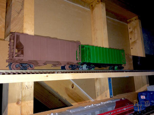
Today I did one thing... with the weather at a wonderful 70+ degrees I sprayed Krylon gray primer on the two hoppers. My wife and I are now on kid watching duty until Sunday, but since they not that young, I may be in the shop tomorrow too and do some final painting. The Airslide is going to be Burlington Northern green with a 1980s BN logo. The covered hopper is going to be Santa Fe brown with the same tagging.  
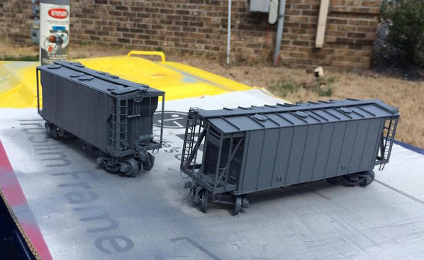
 Hoppers Primed 2

It was impossible to get masking tape to stick to the sintered metal wheel treads so instead I liberally applied a coating of oil so the paint wouldn't stick. If it goes according to plan it should wipe off...famous last words.


I was interviewed today by the corporate communications person from ABB for inclusion of an article in their internal communications. We had a great discussion and she was frankly amazed that a person of my age could learn some much about a new topic so quickly. She asked if you always have to learn so much about a subject before modeling it. I said it helps. In this case understand how things were arranged and functioned let me make a more substantial model. Plus I had the help of many others including you two with some real-world technical experience.


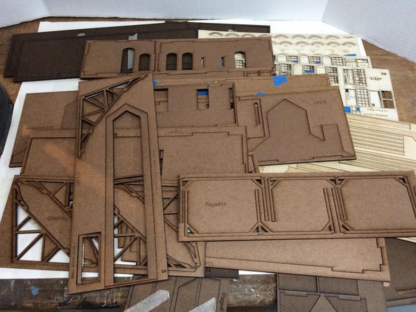
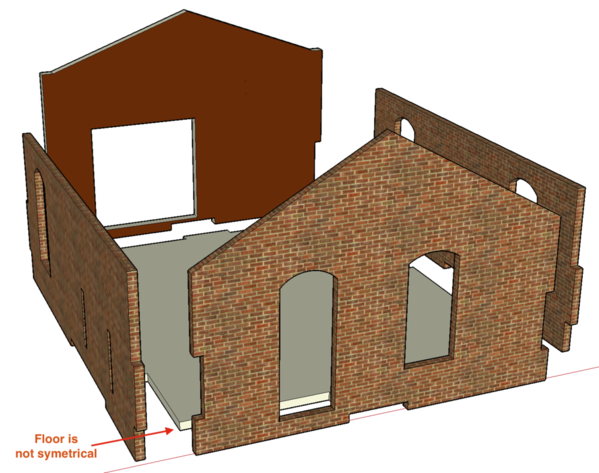
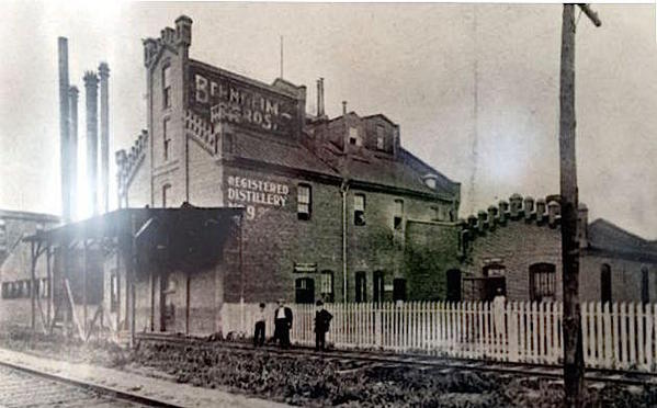
Regarding the distillery. I found out from Andre that all the extra effort I was applying to keep the brick lines off the cutting lines was unnecessary. I made masking lines to keep a 1/32" inch buffer between the bricks .7 pt lines (engraving) and the .3 pt cutting lines. He said the laser will ignore the brick lines butting up against the cutting lines. So I'm going to go back and fix this. These drawings have taken several weeks already. The laser cutting may be fast and accurate, but the drawing creation is slow and labor intensive. The beauty, of course, is you can now cut a thousand and they're all the same.


I am now getting NASA Tech Briefs. In it was a new kind of 3D printer that has been prototyped. Instead of a laser drawing each layer by many, many passes to solidify the polymer, it uses a photosensitive polymer that is UV cure. An entire slice is project upwards through the bath and is focused on a specific layer which immediately solidifies. The next slice's image is projected as the now solidifying object is pulled up one layer's amount. It produces unique parts up to 100 times faster than current technology. They have a lot of work to do on the chemistry, etc., but the concept is genius. Each slice would appear like a view from a cat scan. It will be interesting to see where this all is in 10 years. I would really like a 3D printer and laser cutter in the shop. Nothing could stop me...maniacal laugh, maniacal laugh!

Attachments

Images (1)
  • Hoppers Primed 2

As planned I was able to get the first color coats on the hoppers. One is a Santa Fe brown and the other is BN green. For the second coat I will mask the green to spray on  a black undercarriage for the BN car and a coating of dirty black/brown for the Santa Fe car. When that dries I'll spray a coat of clear Future floor wax to provide a good decal base. That will followed by decals and then dull coat. Once the dull coat dries we'll be ready for weathering with airbrush and Dr. Martin's powders (from MicroMark). It's about a one week project to do this if you really want each step to fully cure before the next. Luckily I have the fire house to work on.


Hopppers first color coat 1


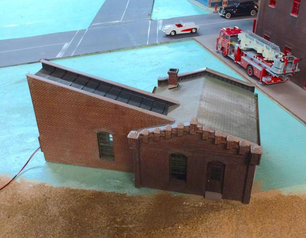
Speaking of the fire house, I got a lot accomplished on that front today. I fully assembled the four walls of the main structure and even plopped it on the layout to see how it looks.


Before putting the walls together I used a surface gauge on a smooth surface to scribe the line for the second floor. I glued some styrene strips to the building to act as a ledge for this floor. For the floor itself I'm using foam core. The LED lighting will generate very little heat so foam core should hold up pretty well.


FH 13


What complicated this a bit (a for subsequent steps) was all that massive structural framing I added to straighten the warped walls. The floor level fell right onto the ones lining the long sides. Les Lewis suggested that it would have been better to use heat to straighten them, but that was after I had already CA'd enough Plastruct structural material to build a bridge capable of holding a locomotive. I know this because it was those very same plastic parts that I did use to build three railroad bridges.


They also go in the way when setting up the clamping for the mitered corners. I partially solved this problem by trimming them back enough for the clamps to have purchase.


FH 16


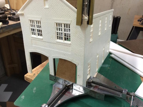
Another challenge what clamping the miter clamp to the front wall bottom. There wasn't much to clamp to and the miter clamp's screw jack is in the middle where there is an opening for the door. I worked around this by using a nice stiff 6" machinist rule from my Brown and Sharp tri-square. I then put a piece of 3/16" Masonite in the opening to provide something to push against. 


FH 14


This method produced a good joint so I repeated it for the other side. When the front was secure I was able to test fit the piece of flooring I cut.


FH 15


I'm not going to include any detail in the second floor so it's really serving as a light block and a place to mount the LED light fixture.


The rear wall didn't have any additional bracing so getting the clamps on was much simpler and the wall went on straight forward.


With all the walls of the main building together I had to take some pictures of the overall building and then stick it on the layout. The roof and tower are just sitting there since there's some particular things you have to do to get the roof properly fitted.


FH 18


It's an imposing structure and even more so when it's in place on the layout.


FH 19


It really dwarfs Saulena's Tavern. I made the first floor ceiling height 16". Fire houses are not little structures. Behind it is where Bernheim Distilleries is going to go. It too will be an imposing building, almost 16" longs and about the same height as the fire station with much more ornate brickwork.


Here's the reverse angle view.


FH 21


Next will be a combination of finishing up the cars and continuing to build the fire house.

Attachments

Images (8)
  • Hopppers first color coat 1
  • FH 13
  • FH 16
  • FH 14
  • FH 15
  • FH 18
  • FH 19
  • FH 21
Originally Posted by Trainman2001:

 . . . .Once the dull coat dries we'll be ready for weathering with airbrush and Dr. Martin's powders (from MicroMark). 


FH 19


Trainman, I use powders a lot but have never bought DR. Martin's.  Are they superior to others or do they have any special characteristic that makes them better than others?


I love the firehouse, and the entire city blow you have there.  Super look to it all.

Mr. Marcovitch, I just had to take a moment to ask a question and add a few comments. First as to the question a few days ago as to "...how many people follow...". I can speak from experience that I regularly look you up at least once a week. I think the nearly 40,000 views that this thread has also speak to that. Your modeling and mechanical skills are awe-inspiring.


Ok, now the question. I just saw you do something that fascinated me. I regularly repaint old train cars. I like buying them cheap and making them my own. I just saw you prime and paint without covering the trucks! I once spent an hour carefully removing errant paint from a poor masking job on 1 wheel. Why did you prime and paint the trucks? I saw the post where you said you would mask the body and apply black to the underside (assuming again you will include the trucks). In my head now you have 3 layers of paint to remove from the wheels and axle (maybe the spring systems too). Did you cover those in oil as well? Please tell us as I am reaching for my turpentine bottle and q-tips to save you from yourself!


Thank you for the hours of enjoyment!

Originally Posted by AtoZ Lewis:

Mr. Marcovitch, I just had to take a moment to ask a question and add a few comments. First as to the question a few days ago as to "...how many people follow...". I can speak from experience that I regularly look you up at least once a week. I think the nearly 40,000 views that this thread has also speak to that. Your modeling and mechanical skills are awe-inspiring.


Ok, now the question. I just saw you do something that fascinated me. I regularly repaint old train cars. I like buying them cheap and making them my own. I just saw you prime and paint without covering the trucks! I once spent an hour carefully removing errant paint from a poor masking job on 1 wheel. Why did you prime and paint the trucks? I saw the post where you said you would mask the body and apply black to the underside (assuming again you will include the trucks). In my head now you have 3 layers of paint to remove from the wheels and axle (maybe the spring systems too). Did you cover those in oil as well? Please tell us as I am reaching for my turpentine bottle and q-tips to save you from yourself!


Thank you for the hours of enjoyment!

lol

Excellent question Mike!!  I'm sure Myles will have an exceptional answer!

Good question. I tried to mask the tires, but the tape didn't stick to the sintered metal wheels, so I chose another, albiet dubious, route. I applied lubricating oil to the threads and flanges in hopes that the paint won't stick well. We'll find out soin enough whether this idea works. It's always so critical to have clean surfaces for paint that I can't imagine it will be to hard to remove the paint. Famous last words. As for the trucks, the springs really don't do any thing so painting them like this won't hurt. The trucks are going to get more paint before this is over. Since they're screwed in from the bottom, i can always remove them if i have to. MTH trucks screw in from the car's insides so you can't remove tme without messing something up. If i need solvent to clean the paint, I'll use scetone which is great for removing dried acrylic.
Alan, not sure about dr martin's quality compared to others. I mainly like tgat it cones in a set with lots of color choices. I think that once you start using powders you will resist using paints for most typical weathering spplications. I'm still going to aurbrush the light coatings of dirt and dust on the car's bottoms, but use powders for the streaking and rust stains. Any areas of concentrated rust will be started usung heavier coats of artist tube acrylics, burnt and raw umber. This builds up some rough texture like heavy rust can do. If you look way back when I built the bridges you'll see how I did this. My Thrall all-door car is an example of WHAT NOT TO DO in freight car weathering. I tried using "dry brush" for tgat, but was way too heavy.

3D printers will, like 2D printers 20 to 30 years before them, go through a steep improvement curve: resolution and speed will both improve while cost comes down.  


In 1984 the first printer I bought was a dot-matrix that needed its own tabel, and slow as molasses, with poor print quality.  Now I have a high resolution color laser that fits under the desk and cost maybe $400.


Give 3D ten years and it will be spectacular.

I looked at the TED film. Interesting stuff. I agree with Lee...in 10 years we won't recognize what's being done by additive manufacturing. I've been following it since the mid-90s and was thinking for a time of going into that industry, but didn't pull the trigger.  The current crop of inexpensive plastic melters don't have the resolution for working in 1:48. The machines that the likes of MTH use in making their prototype shells are the high resolution laser-curing devices that cost a bundle. This new method only has one moving axis (Z). All the rest of the dimensions are created by the sequence of digital images that show each sequential cross-section. In the prototype unit, the projector lies directly below the curing chamber in the large lower section of the printer. I could very easily imagine putting the projection system along side of the curing chamber and directing the image into the bath via lenses and mirrors. This would enable the unit to be put onto a table top. I imagine it would have the resolution us modelers would need.


I bought the paint for the fire house today and will do some painting this week because the weather looks pretty good. I did do some work on the cars. I painted the under body of the Airslide Nato black which is a like weathered black, and did the trucks on both cars the same color.


And of course a calamity happened. I was looking around for a roll of Tamiya masking tape on my workbench, bumped the airslide and knocked it on the floor. Several of the CA'd parts blew off, but overall the car survived and in a few minutes it was all back together again. I hate when that happens!


CH Paint 3rd Paint Op


I attempted to mask the upper works to air brush the black on the Airslide, but it was an exercise in futility. The handrails and other hardware on the ends didn't lend themselves to masking. I therefore, handprinted all the black. I left the wheels untouched... I'm going to do them later. On the Covered Hopper I also hand painted the trucks black, but in this case I took them off the car so I could do it more easily. Tomorrow, I'm going to take the trucks off the green car before doing the wheels. Incidentally, I did attempt to scrape the paint of the tires and although it wasn't easy, it did come off. The oil treatment did work to make it a little less paintable.

Attachments

Images (1)
  • CH Paint 3rd Paint Op

I left the cars sit for a day and was intending on spraying Krylon primer on the fire house, but after looking at the instructions again, and studying the model, I realized that I had some more heavy work to do on it and painting would not be a good idea. It was a gorgeous day outside with the temp a balmy 73 degrees, but it was quick breezy and spraying would have been sub-par.


I first had to fix the broken window mullions. Lee was nice enough to include the right sized styrene stock to make those repairs. The first one was to replace all mullions in one sash on a second floor window. I made a very small cross-lap joint to fasten the pieces together and then fit them to the opening. Unfortunately, it came out a little warped. This side will be facing the back of the layout so I'm not going to mess with it.

FH 22


The second window repair was a front window. Here just one mullion had broken out. Of course in the act of fitting this one replacement, I broke another mullion and had to replace both. In this case, it came out square, although there's some excess CA to be shaped if I so desire. That's the problem with resin, you can't use plastic solvent cement to joint, you must use CA.

 FH 23


I then prepared and joined the tower to the engine house. To get a good fit I had to thin down the tower's wall thickness with a coarse sanding stick. I then clamped it to the main body and applied thin CA both inside and outside of the joint. In a few minutes it was solid.


Lastly, I turned to the roof. Again, there was a lot of man handling the model and fitting that needed doing and if it was painted it wouldn't have been good.


The roof pieces were made oversized and had to be coped into the tower and front overhang adjusted. The walls are neither dead flat nor perfectly square so the cuts had to be custom measured for both roof halves. I first trimmed them so the rear roof overhang was flush. Then I took a piece of 1/8" X 5/16" plastic stock and while holding it against the tower, drew the cutting lines on the roof halves. After cutting on the jig saw and final sanding, I was left with about a 1/8" overhang on the back side, which looked good. 


Les Lewis shows building an attic ceiling, additional pieces with the roof pitch and long purlins that support the roof. He cut a large hole in his so the lighting would be up in the attic, but since I using those flush mount LEDs I left mine solid. Before putting the attic together I had to mount side supports that would hold it all.


FH 24


Les used 1/8" styrene. I didn't have any sheet big enough so I made it out of a sturdy piece of 3/16" Masonite I had lying around. Again, the building is not dead on square so I had to custom fit and cut the final fits.


FH 25


The Masonite's nice and rigid so no additional bracing was necessary.


Onto this floor goes too more solid roof "trusses that had to match the end pieces in pitch and height.


My first attempt wasn't so hot so I remade it. The second still wasn't too good and was low on the back right slope. Instead of cutting another I just packed out the low spot with some balsa sheeting and then sanded it to match the contour of the resin part. The front piece came out dead on. I arranged these two pieces equidistant from the ends and marked their location on the attic floor. Here was the pieces lined up for a fitting.


FH 27


I didn't have much styrene bars lying around so I used 1/4" square for the purlins. I measured and notched one piece on the jig saw and used it as a template for the other one. After a little touch up sanding I glued all of this down to the attic floor. The attic is NOT glued to the model and probably won't be. By gluing the roof halves only to this inner assembly, the entire thing can be lifted off to get at the inside.


FH 28


I was now ready to tape the roof pieces together and do the final fitting for the front and back.


FH 29


The fit came out better than I expected.

 FH 30

The left half was glue to the trusses and purlins with Gorilla glue and I was able to clamp the purlins to the roof so the it cured well. 


FH 31


For applications like this I like Gorilla glue since it expands as it cures and fills any irregularities.


I let this cure for a couple of hours and then after dinner went down to check it and it was solid so I glued up the other side. To clamp this I had to get to the purlins from the ends, but it held. Again a couple of hours later I checked and I had a complete solid roof. Before gluing the roof in place, I did have to sand the top edge of the side walls to get them to conform to the roof pitch. I also had to sand the roof peak mating surfaces so they too would join neatly.


The results were very satisfying.


FH 32


Here's the entire roof removed to show how it hangs together.


FH 33


Lastly, here's that critical back edge fit.


FH 34


With the floors built and the roof fitted, I can now spray the primer and get ready for the burgundy brick-color coat. I will use sheet rock joint compound for the mortar lines after the paints dry. Unlike the chimney on my train station, where I used the water-based joint compound on water-based paint, here it will go over solvent-based Krylon.


The building is quite heavy. Resin is heavy and that chunk of Masonite doesn't help. But this is a good thing since it sits nice and flat on the baseplate.

Attachments

Images (12)
  • FH 22
  • FH 23
  • FH 24
  • FH 25
  • FH 27
  • FH 28
  • FH 29
  • FH 30
  • FH 31
  • FH 32
  • FH 33
  • FH 34

While I am waiting for some glue to cure on a plastic roof, I am reading your Firehouse progress.  Size wise, its a significant building, but your layout demands significant fire protection!   As usual, your posts are very instructive, especially explaining how you solve problems that come up.  In my experience, just about everything involves problem solving, from planning a sequence strategy to figuring out a vision for a particular scene.  You do it so well.

Thank you! The building the model in my mind and playing various steps over and over is one of the great joys of the hobby, especially when it materializes into what you imagined. It's truly the joy of creating.


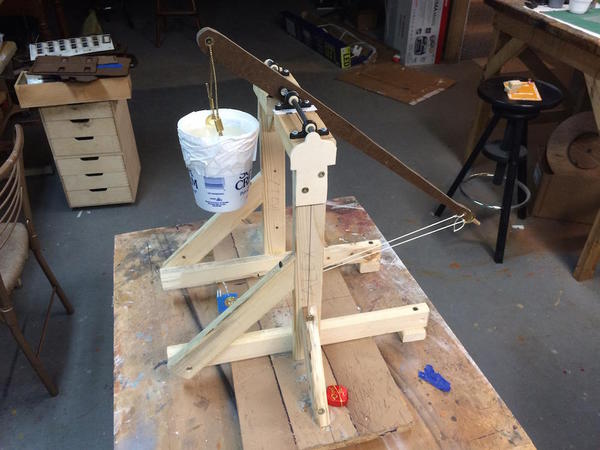
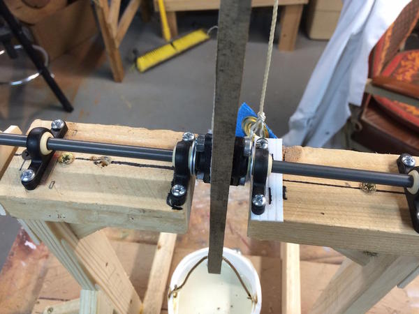
My grandsons both show this ability and are a pleasure to work and problem solve with. Grandson #2's cross bow project was the highest rated in the entire science department. While I helped a lot in some of the challenging construction steps, he designed it, researched it, wrote the entire report, tested it, and presented it. We worked the challenges together. It was as much fun for me as him.


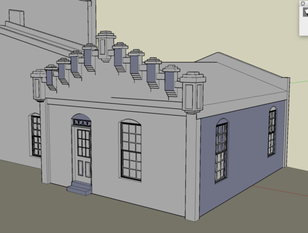
Right now my biggest challenge is making the laser-cut drawing for the distillery. Just when I think it's ready to go, I go back and look at the 3D drawing and find something that I missed or misunderstood. Right now I'm in the process of revamping the intersections of the side pieces with the front, back and middle walls. It was a late pickup, but was critical and the model wouldn't have gone together properly had I not found it. One of the problems is some walls need bricks on their fronts AND backs. Laser cutting only works on one side, so I have to design thin overlays to put the bricks on the back side. This has greatly increased the parts count and complexity. Of course I had to pick a Victorian, brick, factory building. Why couldn't I have picked a clapboard one-room whistle stop station. Nope... not me. My first brass project was that substation.

Originally Posted by Trainman2001:

Thank you! The building the model in my mind and playing various steps over and over is one of the great joys of the hobby, especially when it materializes into what you imagined. It's truly the joy of creating.


I tried your methods, but I lack the imagination so critical to success.  So this was the result......


Seriously, that firehouse could withstand a nuclear blast.  Nicely done!


Bruce

Last edited by brwebster


OP by Trainman: 

My first brass project was that substation.

............................... ............ ........ wow! I feel tiny in comparison reading that          


 Your story is reminiscent of my own grandfathers guidance. An Artisan byproduct of the twenties. Valve and gauge maker by trade. For fun, early Michigan racing(with Allison airplane engine in a Cord), boating, woodworking, a bakers son! mmm Fancy-Cakes, oil painting, scale- "professional" doll houses & some architects models, electronics, and a bit of Rube Goldberg-ing for fun. "Honey, look what I made" (she never new if he was serious cause it always worked, and with brass work & finished wood bases, so serious looking )

Also he was ship-in the bottle guy.

Neither I, nor my Lionel-Gramps could hold a finger to his modeling. Doing things with the end of a bunch of wires never looked like funNice! but bye-bye Gramps.

 His shop & garage were like opening a 3d popular mechanics, or popular science magazine. Gadgets bought and made everywhere. He held a few patents, a couple used in chroming. Thank him for better temp control getting better lasting finishes in automotive chrome. They still use the Accurate Instrument Gauges I think. 

 I was taking off door handles as soon as I could reach them.

The toolbox got a lock at home, so my Grandfathers shop on the next block, supplied my outlet for mechanical learning most days. (he lived miles away, mom&dad bought a house, seen while visiting his shop) I was watched over as he spoke, and I acted as his hands. I did everything myself, except final mill & metal lathe clamp torques that wouldn't do well being hit with a mallet to get the clamp tight. And this was pre-school, literally. (fractions confused me later, but not decimals. I knew those already)

 He had me "master" things by hand, then machine. Wood first, then brass, copper, iron, steel, aluminum. Then came heat & dry powder hardening/pickling. I was his grease monkey, automated drill press feed, and chaser of lost check valve balls & their springs at the shop. This kid was seldom beat in pinewood derbys. It was the best when you could see the losing car was actually adult built (cause the scout was afraid to touch it, looking up to see if it was ok. Real "owners" don't do that. The "it's my car!" attitude cant be faked

 Anyhow when I see or hear about a kid being taught in this fashion, it give me grins And, makes me a little jealous in a way

 Your obviously a "great" Grandpa, and "Thing #1 & Thing #2", they will likely thank you nearly daily for making time for instilling them with these great skills


Heck, I thank you for raising "builders" not more "store bought" children


I'm glad you found the journal also, but just don't replicate what I'm about to explain in today's post.


I finished the primary painting on the cars yesterday, which included a gloss coat in prep for the decals. I did the Santa Fe PS-2 covered hopper first. I went smoothly and came out looking quite spiffy.


CH Decals 6


I used Solva-set to settle the decals into the car's texture. The ATSF and the designation number are single decals that drop over the car ribs so you need it especially on that.


With the easy car out of the way, I tackled the Airslide hopper in BN livery. The problem was that I bought a set of decals for a 50' airslide (the only one Walther's listed). It doesn't quite fit the way it's supposed to. I started with the long fully written out "Burlington Northern" lettering. I didn't realize that it was all one decal connected in odd ways (not one sheet, but with either the top row or bottom connected to each other). In order to fit it to the ribbing on the 40' car I erroneously thought that I had to cut them apart. That began the troubles. I got the B and N in the first panel, and then I forgot how to spell. DOH! I put the two Rs next to the B forgetting the U and O. Microscale decals are quite thin. I tried to detach the Rs to move them over, but they got destroyed in the process. It also messed up the B and N in the first position. 


So I decided to scrap the full spelling and instead put the big BN logo centered in the car body. It's big! It's Bold! It's completely wrong!


CH Decals 1


Since you can never look at both sides of a railroad car at the same time, I decided to do the reverse side correctly.


CH Decals 2


This picture was taken before the decals had dried and settled in. That BN logo is huge and was not fun to position. I also had a problem with the top "T" in the name, but since i still had part of the aborted set from the other side I found a T and installed it thus saving that installation. Today, I touched up a few of the cracked portions of the big decal and prepared to shoot it will Dullcoat. So someday this car will be worth a fortune like those Lionel mistakes that end up being super collectors items. It could happen...


CH Decals 5


With both cars decade and flat coated it was time to start weathering. Before doing this I scraped all the paint off the tire treads first with the Facto and then a final cleaning with Acetone. I painted the centers and backs with a rusty brown and then remounted the trucks on the cars.


First weathering step was a dusting with the airbrush of some sand-colored Model tech paint. I shot it on the bottom and let the light overspray rise up the bottom of the car. I also dusted the roof to fade them a bit. I shot some light gray from the hatches and down the sides to start the process of making it look like these cars are carrying cement or flour or something like that.


CH Weather 1


Next came the weathering powders. I used rusty red, ruddy brown, grimy gray, grimy black and highlight white. I dirtied up the ends, added rust and other grime to the trucks, and played around with the roof.


CH Weather 3

CH Weather 2


I dry-brushed highlight silver onto the roof walks, ladders and grab irons. Painted the couplers rust, added some color accents around the air lines, and put the cars into service.


CH Comp 1


This next shot was done with the iPhone's flash. It accentuates the rust. It's not that bright.


CH Comp 3


And with that dear readers, this little side excursion into some brass scratch-building, kit-bashing is finished.


I also got a nice primer coat on the fire house yesterday, but today the weather was frightening and I worked inside. Do not pay attention to the sloppy shop. I promise I'll clean it up.


FH 35 Primered


Tomorrow, weather permitting, I shoot the color on the fire house. If not, I think I'll clean up the shop.

Attachments

Images (10)
  • CH Decals 6
  • CH Decals 1
  • CH Decals 2
  • CH Decals 5
  • CH Weather 1
  • CH Weather 3
  • CH Weather 2
  • CH Comp 1
  • CH Comp 3
  • FH 35 Primered

Thanks Mark! It makes me want to accelerate the Kadee coupler mods on all the cars and weather more of them. 


Yesterday was another great spring day for painting outside. I got all set to use the Krylon maroon of the fire house and did a test spray on the cardboard that was coving our trash container that is my outside spray stand. It was horrible! Way too red! So it was put everything away and head to Michael's to return it. They gave me a full refund, no questions asked. I knew that Krylon didn't have the right color so I headed to The Home Depot next door and bought Rustoleum red lead-looking primer. The painting went smoothly and the results look right.


FH 36 Paint


The grouting will tone down the brightness a lot and add some more variation to the color.


I wanted to put some fascia trim on the roof front since the resin was not equal thickness. I made it a one-piece affair. But it didn't look right hanging out there all by itself so I decided to add fascia around the rest of the eaves. Again, since it resin, the styrene trim has to be held with CA. The fascia serves another purpose...it hides any gaps between the roof and building fit, and there are some.


FH 38 Fascia Boards 2

FH 37 Fascia Boards 1The fascia's going to be painted the same color as the window trim. The main building is effectively complete except for add-ons (flag pole, chimney--also painted brick color--gutters and drain spouts. So I turned my attention to the interior. There could be lots of  work on the insides depending how crazy I want to get. The doors will be facing 90 degrees to the viewer so view will be limited. I'd like to put in a stairway to the 2nd floor, and maybe a pole. A station of this vintage would definitely have a pole.


First thing I had to do was box in the unsightly reinforcement "structural steel" parts. Bristol board did the trick held to the Plastruct with medium CA.


FH 39 Interior 1


I may leave the 2nd floor dark which would simplify things a bit. Today was our 47th Anniversary so no shop work and a great dinner out at a very authentic German restaurant. Tomorrow I'll get some work done, but will have to pick up folks at the airport mid-day, so the next good session will be Thursday.


Here's how it looks so far.


FH 40 Progress Shot


Roof is supposed to be slate so I'll give it a similar treatment as I did on the chocolate shop and the Victorian train station.

Attachments

Images (5)
  • FH 36 Paint
  • FH 38 Fascia Boards 2
  • FH 37 Fascia Boards 1
  • FH 39 Interior 1
  • FH 40 Progress Shot

Missed posting yesterday, so there's a lot of pics. I completed all the grouting. 


Before tackling the grout I worked more on the interior. First I thought it would look good with some structural steel columns and beams holding up the second floor. 


FH 41 Girders


This didn't work! There simply wasn't enough surface area to really hold the beams since I put them on as an afterthought. Then I kept bumping them when painting the interior. Finally I bumped one off and decided that they had to go. I painted the upper floors all flat black since I'm going to black it out. You can see the hole for the fire pole. It will be supported on the top end in a simple block and a landing pad on the bottom. Since the upstairs won't be detailed I didn't have to build the upper works of the pole which can be pretty elaborate with brace railings surrounding the opening. The 2nd floor is a piece of foam core, the hole was cut with an Xacto lined with a piece of thin styrene and glued with thin CA. If I were to detail the second floor, it would have a kitchen, eating area, dormitory and bathrooms. This was modeled after a real structure in Conn., so all of that would fit in the building.


FH 42 2nd Flr


The interior is sort of sea foam green, some nice institutional, neutral color.

 Fh 43 1st Flr


I have to detail the walls since there a no doors showing on the inside matching those on the outside. The stairway to the 2nd floor will be hidden behind an angled wall with the fire pole in front.


Grouting, as mentioned, started with the tower. It was basically the same as a 1:1 scale tiling grout job. I'd smear the material on, liberally, then using various sized scrapers I cobbled out of sheet styrene, proceed to scrape of the excess. I then dry-wiped the bricks with a paper towel. Then it got annoying. I had to use dental tools to scrape excess out of all the various level changes. 


FH 45 Grout 2


After cleaning all the corners I took a lightly wetted rag and wiped it down again. While it still left a film, it was damped down nicely when I used the alcohol/India Ink wash. This little bit took over an hour and half.


Once the tower was done, the rest of the job went quickly, due both to the learning curve and big flat surfaces. I sped up the process by using a better selection of spreaders and laying on the first coat thicker so I could spread it over a larger area in one go. 


FH 46 Grout 3


Remember, at this time the windows and trim are not finish painted.


While it looks pretty good just grouted, it's just too fresh looking.


FH 47 Grout 4


And here's the building after two coats of alcohol/India Ink wash. I really wanted to damp down the whole deal and two coats did it. Notice, that I'm now putting the fire house on the front of the layout. It fits and gives me a better chance to detail the ground floor interior.

 FH 48 Wash 1


I think the brick looks much older and more natural with this level of wash. When the roof is finished, trim painted red, gutters and drain spouts in place, chimney (which reminds me, I have to grout that!), and the doors in place, plus the base plate finished, it will look very authentic. It's a shame that the beautiful Corgi fire trucks are 1:50 and all the other vehicles are 1:43 because they look so small. That's a big difference in scale when dealing with trucks. The Mercury convertible in front of the house is almost as long as the American LaFrance 1950s pumper.


FH 49 Wash 2

FH 50 Wash 3

Next time, I work on the interior and do the trim painting.

Attachments

Images (9)
  • FH 41 Girders
  • FH 42 2nd Flr
  • FH 45 Grout 2
  • FH 46 Grout 3
  • FH 47 Grout 4
  • FH 50 Wash 3
  • FH 49 Wash 2
  • FH 48 Wash 1
  • Fh 43 1st Flr

Great work on the cars and the firehouse. I'de really like to see a close up of the brick after the alcohol wash.


Aside, my wife and I celebrate our 45th this August. congratulations on your 47th. Life really goes by pretty quick doesn't it? Sharing it with a great gal makes it all the better.


Ron H 

Thanks all!


To satisfy the requests:

Here's the material I used for mortar. Remember, it will dissolve water-based paint right off the model so if you're going to use it, first seal the surface with a non-water-based flat like Dull Coat or a solvent-based fixative.


IMG_3067


For the second request, here are some closeups of the brick work with the wash.


IMG_3066

IMG_3065


The hardest places to remove the excess "grout" was in the corners of the recessed areas as seen above. I may try and go back and treat them with something, possibly some red-brown weathering powders. I haven't used any let and I want to dust the bottom section with some "mud" air brushed on to simulate the accumulated dirt splashed up by rainwater.

IMG_3064


The wash did 2 really good things. It made the mortar look real, and it changed the brick color by toning down the orange and giving it a really nice old brick feel. Even without the windows being painted the building almost looks finished. I'm probably going to paint the window sills a concrete color. I'm also going to spend some quality time looking at brick buildings for the nuances like where any moss would grow, any streaking, how downspouts and brick interact.

Attachments

Images (4)
  • IMG_3067
  • IMG_3066
  • IMG_3065
  • IMG_3064

AZ, thanks (Andre too), but it's not done yet. I still have plenty to do to screw it up.


It wasn't really a special deal. Les Lewis of Westport wanted to market it as a kit and made the first one from his styrene master, but it didn't come out like he wanted. Some of the problems I've had to contend with in the build (warping, varying wall thicknesses, etc.) were the specific reasons why he chose not to market it. I saw Les laying the individual styrene bricks at the '07 York show and said if was making a kit, I'd buy one. That was the deal.


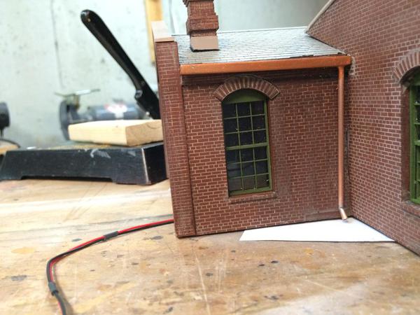
I wanted to prime paint the drain spouts, gutters and other detail pieces including the doors. Unfortunately, I had to spend over two hours rebuilding the down spouts and gutters. Les was nice enough to construct out of brass gutters from Special Shapes U-channel plus soldered 3/32" brass tubing. Unfortunately, for the jog bends in the down spouts so they would hug close to the building, he simply butt-soldered the angled joints. All but one of them had broken in shipment. I didn't even realize this until I examined the parts closely today. I thought they were just separate pieces.


Butt soldering wasn't going to work so I made 1/16" brass plugs to provide more solder area. 


FH 55 downspout 1


This was the first one I tried. I quickly realized that I needed to bend the plug too. I did this by making a razor saw slice and using the saw kerf as enough space to make an angled bend. I tinned this bend and soldered it into the previously attached angle tube. I cut the plugs very short just to create a bit of a stub. It stabilized the joint and gave much more solder area.


Here's the completed joints. There are two joints in each jog.


FH 56 downspout 2


There were some gaps that I filled with CA before priming them. I said that three of four were broken in the box. Well I brought the brass upstairs fix'n to take it outside to paint it, and poof! the last joint gave way. Back to the shop to make another repair. I eventually did prime all the brass parts. The downspouts/gutters will be painted copper and then patina'd. 


I decided to start the detail painting on the main building while the primer dried. I'm using Model Tech's concrete gray which I really like. It's also water-based and benign so it doesn't have a problem with the Rust-o-leum primer red underneath. I have some new  Tru-Color paint, but it's acetone-based and would eat the primer.


FH 59 Window sills


I also painted the tower roof Nato Black and the parapet cap the concrete gray.


FH 58 tower roof


I'm not going to do much detailing of the interior doors. You really won't seen them. But if you do get a glimpse, I masked and painted the door's shape onto the interior wall.


FH 57 int doors


I need to make some kind of shelving/cubby system for the interior walls where the firemen's garb would be stored. I did get a hold of some fireman's outer wear in 1:48 and need a place to hang it all.


Next session I'll build the shelves and start on the roof detailing. I also need to make/buy hinges for the four front doors. Les provided no way to hand them. I could glue them in position, but I'd like them to be working.

Attachments

Images (5)
  • FH 55 downspout 1
  • FH 56 downspout 2
  • FH 59 Window sills
  • FH 58 tower roof
  • FH 57 int doors

Lee, I used resistance. I'm almost using all the time now unless I'm doing electronic work.


The only problem I have with the American Beauty is that the tweezer points cross if you put a little too much pressure on them. When they cross, they spew the part out...somewhere. I keep bending them to ensure that they're centered, but there's a lot of side play in the system so you really can only use moderate pressure at best. I'm saying that because the tweezers had a hard time holding onto the tubing pieces that make up the downspout. The job was more frustrating than it seemed it should be. I don't know how Les Lewis was able to butt solder all those pieces together.


Actually, the smaller the pieces the more RSU shines.

Your welcome!


Today was fun since I was actually building things and not re-building them. First was more detail painting on the tower roof.  I also found an extra Grandt Line door for the entrance to the hose tower from the inside. I finished the chimney and installed it. Lastly, I started fabricating the cubbies that will hold the fireman garb.


I added some gloss black "tar" lines between all the rolled roofing on the tower. This really makes it look real (to me). 


FH 60 Fresh Tar


The tower gutter and downspout goes just below the tar paper lip in this picture. I should dust the whole area with powders, streaking it and toning down the "newness".


I grouted and painted the chimney yesterday. Today I went back and painted the flues flat black, dusted the hole area with dirty black weathering powder and then made chimney flashing out of black construction paper. Many modelers leave out flashing, but again, I think it just makes it look more real.


FH 61 Chimney FlashingThis is a really closeup pic, but those bricks still look amazing. Lee, this is the 3-inch rule. Before installing the chimney, I marked out its area and scraped off the gray primer. I wanted to have raw resin so the glue would stick better especially since I wasn't going to remove the shingles themselves. I used Gorilla Glue to hold the chimney specifically for its ability to expand and fill in gaps. In some instances, the upper gap between the chimney and the roof slope should have a "cricket", which is a small triangular roof that sheds water in that V-notch so it doesn't get trapped and freeze there. Since this firehouse is in Kentucky, I probably will leave out this detail. 


FH 62 Chimney Install


I found this door and make a quick frame. To stick the door to the wall I tried a new product: Glue Dots.

FH 63 Int door install


I bought them at Michael's when I went looking for some more DAP Quick Stick contact cement strips that also work well. The glue dots are about 3/16" in diameter and are on a strip. You touch the object to be stuck to the dot which picks it up, and then press it to where you want it to be held. Bingo! Holds tight and instantly. Four dots held the door tightly. No slop, no mess.


Glue Dots


I have these fireman's coats that need a place to hang them.


FH 65 Fire Gard


To hold them I'm making a series of 8 scale feet long by 7 scale feet high cubbies. There will be a shelf to hold their helmets, which I still have to make. I'm using scrap styrene that I have lying around so you see some differences in the textures. They won't be visualized at all, and will be painted fire engine red... appropriate, don't you think? They're not finished or fastened in this picture.


FH 64 Cubbies 1


I'm making five. I guess I could make six, but frankly, it was getting boring. When done, I'll stick these to the walls with glue dots also. I have to make helmets and I think it's time for me to get into resin casting. I can get a full starter set at the LHS for under $50. I've been putting this off, but the helmet project makes sense to do it in resin. One master... many copies.


Tomorrow, the chimney will be cured so I can start painting the various shingles different shades of gray to make it look more like real slate. Then I'll weather it and paint the trim. I was just thinking as I'm writing this... I wanted to make the roof removable, but the gutters are attached to the roof and I will want the downspouts attached to the walls also, otherwise, they'll get broken eventually. So the roof will need to be fastened to the building. The building itself will be fixed to the base, but the base will not be glued down to the layout. I'll make a plaster socket just like the substation to blend it into the layout.


I have to produce hinges for the big doors. I've been doing some research and am quickly coming to the conclusion that these too will have to scratch built. Anyone have any good ideas?

Attachments

Images (7)
  • FH 60 Fresh Tar
  • FH 61 Chimney Flashing
  • FH 62 Chimney Install
  • FH 63 Int door install
  • Glue Dots
  • FH 65 Fire Gard
  • FH 64 Cubbies 1

Remember, the great brickwork started with Les Lewis' great bricks! By using individual bricks Les was able to do two things that added to the realism. First, the act of gluing on individual pieces created a non-uniform look that replicated real life. Second, it made very sharp and deep mortar lines that lend themselves to my way of grouting.


That being said, I'm working with Andre Garcia on laser cutting the distillery. I suspect that the mortar lines will also be sharp and deep. He did a test cut for me and I'm waiting for it to arrive. It will be on MDF. From his photos, the mortar lines look pretty good. They won't have much irregularity being laid down on my computer, but I suppose I could build that in.

First of all, I got the sample cutting from Andre. It's one wall section of many for the distillery. The cutting alone will go into the hundreds. In the sample, I made the brick lintels part of the brick work, but in later revisions I re-designed them to be appliques made from 1/32" stock. The test proved that my drawing method was correct for laser cutting. Also, notice that the brick is arrayed in "Common bond" where every 6th row are bricks on end connecting to an imaginary inner row of bricks. That different row definitely caused extra drawing.


I immediately sprayed it with Rust-o-Leum red primer and applied some mortar to see how it worked. I didn't let the primer dry very long and definitely rushed it, but the results were promising and I just sent massive cutting files to Andre for the main distillery bldg and the "kitchen".


Laser test 1

 Clearly, the Les Lewis individual brick wall looks better, but I'm pretty confident that the laser cut wall will work just fine. This was a really quick job.

Laser Test 2


After the experiment, I was back at work on the fire house. I put in the middle shelves on the cubbies, painted and then installed them.


I thought it might be interesting to see how I transfer and make precise fits in styrene. I use the digital caliper. The inside and outside jaws repeat the same exact measure, so one can measure the space between two points and use the other side of the caliper to transfer that exact distance to a work piece.


FH 66 Meaure


And here's where I scribe that distance to the styrene.


FH 67 Transfer


By dragging the point across the surface while keeping the other point in contact with the edge, the caliper works as an effective surface gauge. And don't forget to tighten the locking screw before transferring the measurement. I use the NWSL Chopper to cut the piece to length.


FH 68 Cubbies 2


I taped the pieces to a piece of wood and then airbrushed a couple of coats of Vallejo bright red. 

FH 69 Cubbies 3


And here's the cubbies installed using glue dots.


FH 70 Cubbies 4


That is not the house's base. it's one of my cutting pads.


It was time to paint the windows. One of the advantages of having a building with the windows included in the molding is that they fit perfectly. And the drawback is that it would be very hard to airbrush them. Instead, they all have to be hand painted. I'm pretty good at the that so it wasn't a bad task. Here's the first window. The paint was still wet some what looks like misses are actually highlights reflected off wet paint.


FH 71 Window Paint 1


And here's the first side complete.


FH 72 Window Paint 2


To facilitate painting, kept turning the whole building 90 degrees so I was always painting on the top of the edge I was painting. This was especially valuable when attempting to line the edge between the brick and the framing.


Here's the front end.


FH 73 Window Paint 3


I got some more of the 3rd side done. The tower will be "fun" to do. I will probably give a little alcohol wash on the finished frames to tone them down a bit. The iPhone registers the red as a little "hot". It more red than it appears in the pictures. The window painting will be done tomorrow. I made a scan of the main doors so I can import them into Illustrator and design some hinges. I also have to get to casting some resin fire helmets. I wonder if Artista has any?

Attachments

Images (10)
  • Laser Test 2
  • Laser test 1
  • FH 66 Meaure
  • FH 67 Transfer
  • FH 68 Cubbies 2
  • FH 69 Cubbies 3
  • FH 70 Cubbies 4
  • FH 71 Window Paint 1
  • FH 72 Window Paint 2
  • FH 73 Window Paint 3
Last edited by Trainman2001

Today, I finished the hand painting of all the windows. It was a careful, finicky job, but came out nicely. The tower and the back two windows were especially challenging since the building itself blocks my normal painting style. As it was, the results didn't suffer.


FH 74 Window Paint 4

This shade of red does have a bit of orange in it.


After placing it on the layout for these next shots, I had my wife "inspect" it. She thinks that the building should be moved back to my original spot since its size blocks view of smaller buildings behind. I am tending to agree with her. I'm also going to get another set of LED track lights from Lowe's. I'm still not happy with the level of illumination on the front of the town.

FH 76 Window Paint 6


I thought this would be a nice looking building, but frankly, it's exceeding my expectations. I'm still noodling the door hinges, and will probably compromise. I'll use brass tube and axles to make the actual working hinges (hidden) and make up some styrene fake hinges that will be on the door's surface. This will prevent me having to do any silly jewelry work.

FH 75 Window Paint 5


Andre has the distillery drawings and cutting will proceed after York.

Attachments

Images (3)
  • FH 76 Window Paint 6
  • FH 75 Window Paint 5
  • FH 74 Window Paint 4

Thanks. I just bought more of that color. Vallajo has many shades of red in their rack at the LHS. I may have purchased this red to match some decals on an airplane kit that grandson #2 was working on four years ago.


Today, after buying a Alumilite resin starter kit and more paint, I painted 9 fireman's outer garb that will go into the cubbies. I want the resin to cast fireman's hats and boots. I'm sure I can sculpt at least one good one of each, but certainly couldn't do it multiple times. That's where the resin comes in.


IMG_3110


The coats were molded in white resin.


Underneath them are the printouts of the fireman's helmets that I'm going to attempt to model.


IMG_3112


And behind them is the Alumilite resin casting starter set. While the starter set is rather small, I'm really only planning on resin casting small details. Once I get into larger stuff, I'll have to get some different materials.


IMG_3111


Tomorrow, I'll be sculpting and attempting to make some molds. The originals will be made out of Super Sculpey. It hardens at 275° so it will hold its shape when being covered in mold silicone. But... it's very friable and thin sections don't hold up very well. That's the main reason to cast the parts instead of making them all out of Sculpey. I had a lot of spoilage when using it to make the substation light fixtures.

Attachments

Images (3)
  • IMG_3110
  • IMG_3112
  • IMG_3111

Yesterday I started to attempt to craft a decent fire helmet and boots. I foolishly tried to model the ribs in the helmet. Why...? I have absolutely no idea since the chances of visualizing them while the helmets sit on a shelf in the cubbies buried in the firehouse are effectively nil or zero. I'm using the more stiff Sculpey, but still when working with tiny fragile items, just the act of holding the object smashes the details you just created. My first try ending up looking like this.


FH 81 HELMET DISASTER


There are names for things that look like this and none are suitable for posting on this forum. I then created one that was passable, heated it in the toaster over, and then dropped it on the kitchen floor before I got it down to the basement and the back of the brim broke off. 


So today I tried for a third time and this time left off the ribs. It came out as a decent, identifiable, helmet.


FH 82 HELMET MASTER That wooden log in the foreground is a toothpick. I baked it, and while it was cooking I made some boots.


FH 84 BOOTS MASTER


I looked at some YouTube vids of resin casting and decided to make the mold box out of Legos, of which I have an adequate supply. The starter kit is really small, but luckily my parts are really small too. 


Here's the parts nestled in the mold box.


FH 83 SILICONE MOLD 1


After I took this pic I further sealed the Legos and added another row of bricks to make the mold box higher. I didn't create any air vents, and I'll do so in the cope of the silicone bottom mold after it cures. Before I poured the silicone I put a series of dents into the clay that will serve as reference keys to keep the two halves of the finished mold.


I mixed the silicone at the recommended ratio of 10:1 by weight using my digital scale, and poured the mold. This will be cured tomorrow and I'll pour the other half of the mold tomorrow. We're going on a trip starting Friday so you'll all have to wait (as will I) to see if this experiment in resin terror actually works. Once the mold is ready, I can make multiple copies quickly since the resin cures in minutes, not hours.


FH 80 SILICONE MOLD 2


Clearly, using liquid silicone is more efficient than using liquid latex. It's also much more expensive and is not suitable for pouring over rocks to make rock molds. 

Attachments

Images (5)
  • FH 81 HELMET DISASTER
  • FH 82 HELMET MASTER
  • FH 84 BOOTS MASTER
  • FH 83 SILICONE MOLD 1
  • FH 80 SILICONE MOLD 2

When I checked at 1:00 this afternoon the silicone had not completely cured. It resembled my pancakes I make that sometimes, when the batter thickens, cook on the outsides and exude uncooked batter from the inside. I put the legos back against the mold and let it cure some more. I moved it upstairs where the temperature was higher. Right now it seems like it's getting more solid, but I won't open it up until after the trip we're about to take tomorrow.


So to fill the time, I painted the roof, the trim, and started finishing the base board.


The roof is made to look more like natural slate. I do this by randomly painting shingles with a purple/gray, a green/gray and lighter gray. It's quite subtle, but kills the uniformity of the sprayed gray roof. I also used some gloss black at the chimney base to simulate more tar sealant.


FH 85 ROOF PAINT


I then painted the roof trim and the trim surrounding the upper edges of the main building. I used two coats and did it entirely by brush.


FH 86 ROOF FIN


Here's the front trim in detail.


FH 87 TRIM PAINT


I masked where the building would go so I wouldn't groove under the walls. I laid out the base on 8 scale foot expansion grooves using a sharpie. 


FH 88 BASE LAYOUT


I then used one of my many dental tools to engrave expansion grooves into the Masonite.


FH 89 BASE GROOVES


Before airbrushing Model Tech concrete, I ground down the front edge to be the curb cut to ease the fire trucks entrance and egress onto the concrete pad.


FH 90 BASE PAINTED


Lastly, I dropped the building onto the base for a status shot.


FH 91 STATUS SHOT


The base needs some weathering (as does the building). This will be done when we return on May 4th. I'll be checking in on the iPhone, but probably not posting (as much).

Attachments

Images (7)
  • FH 85 ROOF PAINT
  • FH 86 ROOF FIN
  • FH 87 TRIM PAINT
  • FH 88 BASE LAYOUT
  • FH 89 BASE GROOVES
  • FH 90 BASE PAINTED
  • FH 91 STATUS SHOT

Hi guys! I'm back. The silicone for the first side of the mold took way too long to cure. I pulled it apart just before we got on the road for the trip and it was cured. As soon as I got back into the shop, I turned it over and poured the second half of the silicone mold. Quickly I realized the first part of the problem. I thought I was measuring the ingredients using grams and wasn't. The digital scale was set to ounces so the 10:1 ratio was completely goofy. When I poured the second side, I made sure to get the ratio right and it cured in 6 hours. I also took it out of the chilly basement and moved it to the warm sun porch.


All of this, however, is moot. The entire exercise was a bust since I didn't have any "official" mold release to keep the two layers of silicone from sticking together. Instead I used vegetable oil. It didn't work! The top and bottoms were completely fused together. I basically destroyed the entire mold in trying to get it all apart, and scrapped the whole idea. I did a lot of research into resin casting during this part of the project, but don't want to invest any more money in casting these silly little details that no one will ever see. So I'm going to hang the coats in the cubbies, but leave out the boots and helmets.


I'm not finished with silicone mold making. I'm planning on making my own masters for the arches and retaining walls for the elevated portion and will probably use silicone to make the molds. Instead of resin, I'll be using Hydrocal since I still have a lot left and it's much, much cheaper than resin. This is not fully decided at this point, I may still go commercial (Scenic Express), but it's like 17 feet of wall that needs to be covered and that's lots of $$$ to buy. Silicone mold material isn't cheap either, but you need a lot less of it.


I did get some constructive work done on the fire house. I got the roof vents installed along with drilling the holes to accept the flag pole. I'm installing that after I stop manhandling it. 


FH Vent Stacks


I then started installing window glazing. For the tower I just used long strips of .010" clear styrene. For the second story which will be dark, I glued the glazing directly onto the walls, but for the first floor which will be more visible, I mounted window frames on the glazing and then fitted them to the walls.


In all cases I used the MicroMark Pressure Sensitive Adhesive which is a reasonable way to attach glazing. I applied the adhesive to both pieces, let them set up and then put them together. Getting glazing up into the top of the tower would have been much easier if I hadn't had to glue on the roof piece, but I couldn't have glazing in place when doing all the painting. Luckily, it's just big enough inside to get my hand (and arm) all the way up. And also lucky that I don't have large hangs (a definite disadvantage when I play guitar).

 FH Window Install 3

I painted the window frames by sticking all the pieces to reversed masking tape. I used a diluted plastic tube cement applied with a tooth pick to glue the frames to the glazing. It's one of the reasons why I like to use clear styrene instead of clear acetate. Acetate is not glueable with solvent cement.

 FH Window Frames

I had to paint the insides of the window mullions the frame color (a light green Model Tech paint) since they had red paint from the outside color which looked terrible.


FH Windows Install 2

My cubbies created a problem for the two rear windows leaving no room for the frame so I to do some selective hacking to get them to fit. If I had thought a little more ahead, I could have made the cubbies a little narrower so the windows wouldn't be in play. Oh well...

FH Window Install 01


It's Mother's Day weekend so work will commence on Monday. I just have to glaze the doors and the transom windows above them and it's onto the main doors. I'm still noodling how I want to hinge them. It's good practice since I'm going to have to make similar hinging for the three sets of doors on the engine house (future project).


Andre says there's some errors on the Distillery drawings that have to be corrected before cutting can begin. I work on them soon too.

Attachments

Images (5)
  • FH Vent Stacks
  • FH Window Install 01
  • FH Window Install 3
  • FH Window Frames
  • FH Windows Install 2

Super!  The detail you have is extraordinary.


About the hats and boots.  I understand the frustration with the molding.  


We work in very different ways, Trainman, and you may not like this approach, but for what it is worth.   If I were making, say, a half dozen fireman's hats and boots to hang on a wall, etc., I might do it this way:

HATS - get some of the things shown in the photo below.  Th3y come in several sizes but they e are a bit more than a 1/4 inch or 3/8 inch wide.  I think they are called eyelets and made for sewing.  Forget the donut - work on the thing that looks a bit like a priest's wide brimmed hat.

Slide1


Put the future "hat" on waxed paper or some other surface that glue doesn't like (teflon, etc.).  

Using a sharped pencil point and depending on surface tension to help you out, put a drop or two of yellow wood glue on the bowl of the "hat" and spread it over the entire top and sides of the bowl.  You way need to use a second pencil point to hold the "hat" firmly in place while you do this.  Then let it dry.  The dried glue will expand the size of the "bowl"  Depending on things, you may need a second application.  

Slide2


Using more glue, apply a thin layer as shown to form and extend the back brim of the firefighter's hat.  Let it dry.  It will be fragile, but . . . with luck you can make six or so hats, cheap. paint them (carefully, they are fragile).  Just takes a day or two because you have to let the glue dry overnight.  Other glues, or epoxy instead, would work, too, I imagine, but I've grown used to using yellow glue . . . 

Slide3


BOOTS - there are two ways I would do it:

Expensive: buy a set of firemen, as below, cut their boots off, and savee the rest of the figures for passengers in trucks or cars or where you won't see their feet. 

Lot 8 pcs O scale 1:43 unpainted figures Fireman Model Railway Train layout


Less expensive: takes some figures you have but can't use, or that are cheaper, and apply yellow glue to their feet and lower legs to widen them until they look like boots, as was done to widen the hat. 

Attachments

Images (3)
  • Slide1
  • Slide2
  • Slide3
Last edited by Lee Willis

Glad to be back. And that dear friends is exactly why I take the time to interact with all of you each work session: Getting sage advice from other modelers who see things differently. Lee's idea, while I may or may not do it, is terrific. I'm also thinking that if I perfect it enough, I can simply make ten copies of each out of the Sculpey itself. I know how to make the hats pretty quickly and it would be faster than building up layers of glue and having to wait for the multiple drying times. The boots are cut out of a slab of rolled clay and then rounded out. I used another donut-shaped piece for the wider top. I can make these quickly too.


Andre and I are working back and forth correcting some of the errors that crept into the massive distillery drawing I sent. To make the little added pieces of material that hold the cut parts to the sheets (nubs?), I used the "anchor point add" tool in illustrator and then split the line at that point, separate the points to make a gap. This gap then has the un-wanted effect of turning one object into two (or more depending on the number of nubs). His software was then drawing phantom lines between the end points of these sub-parts which the laser would interpret as cut lines. I've gone back and reconnected all the points and overlaid little white squares with no outlines to block parts of the outline and make the nub gaps. This should correct the problem. If not, I've just wasted a lot of time. We'll see...

Last edited by Trainman2001

The drawings are all modified and back in Andre's hands. I'm excited to see what they're going to look like cut and see if it goes together as I designed it. As I said before, I have a new found respect for the likes of Bar Mills and B.T.S. in the design and creation of complex laser-cut kits.


Finished installing all the fire house windows and started on the main doors. After interacting with Les Lewis I decided to make the simplest hinge possible; a brass rod into a drilled hole on the building and a socket in the base plate.


FH Hinge 1

I eyeballed the hole position in the door top and bottom and drilled the holes with a 0.032" drill about an 1/8" deep. After CA'ing the brass pin into the hole, I used the door to make a corresponding mark on the building frame and drilled another hole. This hole was very close to the corner and the pin vise didn't have clearance to drill straight in. I fudged it by putting gentle side pressure while drilling which bent the drill so it was almost vertical while rotating. I kept finger pressure on the drill shaft to maintain this curve and got a reasonably straight hole. You have to be gentle since miniature drills are fragile.


After fitting the doors two of them were a bit long. I ran some heavy masking tape across the bottom in line with the building's bottom, then stuck the door to the tape when its pin was fully seated in the hinge hole. This established a very nice cutting line for the fine-toothed razor saw. I had to deepen the bottom hole a bit since I cut part of it off.


FH door trim

I was then ready to paint the doors and glaze the windows. I used the same red color for the outside of the doors. The insides will be painted the light green window frame color. The regular bottles of Vallejo paint say not for air brushing. I assumed this was because it wasn't thin enough. I used Testor's acrylic air brush thinner to thin this paint.


That apparently was a mistake. I've used isopropyl alcohol for thinning Tamiya acrylic for years with zero trouble. The Testor's thinner seemed to cause the Vallego paint to clump...terribly. I would spray for a minute and the gun would shut off. I had to disassemble it completely, clean it out with Model Tech cleaner, alcohol and finally acetone. It was fully clogged. I tried again and it happened again. I spent much more time cleaning than painting. Vallejo has an airbrush paint line, but didn't have this shade of red.


FH hinge 2


The trickiest part to this whole affair will be locating the hinge holes in the baseplate. I'm going to tape the doors into position and align the back of the fire house on the base and tape it, then swing it down into position so the bottom hinge pins will mark their location of the base. I'm going to bush the bottom holes with a piece of K-S 1/16" brass tube that just so happens has an i.d. of 0.032". I'll use Gorilla Glue to hold the tubes into the base and drop the hinge pins into the bushings as I lower the building into final position.


For the engine house, the doors will be very similar (although a little bigger), but in that case I want to make them remotely operable. For this installation, I'm thinking that I'll mount the lower hinge assembly into its subassembly that can be installed after the building is in place on its base. It will have a series of levers and bell cranks underneath that will open all three doors simultaneously either by servo or push cable. Building the fire house has been good practice in designing a more sophisticated structure.

Attachments

Images (3)
  • FH Hinge 1
  • FH door trim
  • FH hinge 2

That's great! Perhaps you can try fitting some of the parts together to see if they actually fit as i drew them...?


I airbrushed the interior side of the main doors the light green. Again, I used the Model Tech paint. This paint did not have the problems that the Vallejo had with the clogging. The model tech bottle threads directly onto the Badger adaptor and can be sprayed without thinning so it's very easy to use. I then measured and cut the door glazing. There was some variation in the opening sizes so I had to adjust each piece to fit correctly. I used RC-56 canopy cement to hold these windows in. It's a PVA glue that had good tack and dries almost invisible. This picture was taken before the cement dried some it's still quite visible behind the clear styrene.


FH Door Windows


After everything dried I inserted the doors up into their respective hinge pin holes and then taped them to stabilize them. I lowered the fire house into position on the base and marked where I thought the bottom hinge pins would best fall.


FH Hinge 3


I drilled on these spots the .032" drill and then test fit them again. When I got them seated correctly I opened the holes out to 1/16" and prepared some of the 1/16th brass tube that would serve as a more substantial pivot instead of directly into the Masonite. The doors needed a little trimming to get them to open and close properly. Here's one of the test fit sessions.


FH Hinge 4


With all this done, I'm going to do some pre-weathering of the base plate and start preparing the fire pole base that will be at the rear of the station. I'll permanently mount the station, put the fire coats into the lockers and then mount the 2nd floor. Only then can I finally install the fire pole. Get'n near the end on this one, and just in time. From what I hear from Andre, I'm going to have a distillery to build before long. 


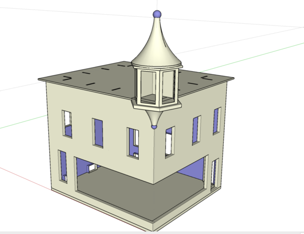
I've just designed another kit for cutting using all the techniques I've learned from the distillery project. For example, I can now paste the Brick arrays into the wall perimeters using a keystroke instead of carefully hand fitting the array. It took minutes instead of days...literally! This is the Night Hawks Cafe project. It will make a great little Victorian tavern building with turret with the interior a replica of Edward Hopper's famous Night Hawks painting which resides at the Art Institute of Chicago. I've written about this in an earlier post.


There are more buildings for the distillery that will be designed later depending on how good the main buildings come out.

Attachments

Images (3)
  • FH Door Windows
  • FH Hinge 3
  • FH Hinge 4

I think you're going to have to contact Les Lewis at Westport Model Works. I seriously doubt that he kept the silicone molds that he used to create this one. The next best choice would be to draw it up and get it laser cut. I'd hold on that choice until I see how the distillery comes together. Unlike this model where the corners were all tapered at 45 degrees so the joints wouldn't show, I've designed the distillery to have interlocking corners which will show some joinery. I've designed cover pieces to hide some of the most obvious joints, but they won't be invisible. I suppose that I could design the corners of a laser cut piece to be beveled so the corners would butt up flush, but it's MDF and I don't have the fixtures to form a really straight bevel.

Originally Posted by Trainman2001:
 
Thanks Trainman.. I did exchange email with Andre and it is an option. I look forward to seeing your brewery design and what you think of the custom work. Your detail work is amazing.
 
Les Lewis is missing a opportunity here by not offering this as a kit. I was surprised by the lack of firehouse kits available, you would think everyone would have one in their town.... I have only been at this a couple of years and start to see the end of the town. I was going to build a refinery on the last plot of land, but changed my mined when I saw this.
 
Cheers,
-r

I think you're going to have to contact Les Lewis at Westport Model Works. I seriously doubt that he kept the silicone molds that he used to create this one. The next best choice would be to draw it up and get it laser cut. I'd hold on that choice until I see how the distillery comes together. Unlike this model where the corners were all tapered at 45 degrees so the joints wouldn't show, I've designed the distillery to have interlocking corners which will show some joinery. I've designed cover pieces to hide some of the most obvious joints, but they won't be invisible. I suppose that I could design the corners of a laser cut piece to be beveled so the corners would butt up flush, but it's MDF and I don't have the fixtures to form a really straight bevel.


Les did attempt to offer it, but it proved too difficult for him to create. He was using open molds which made it very difficult to control wall thickness. As I noted when I started the project that I had severe warpage of the main parts. There's also a significant twist in the hose tower, but it's only really noticeable when you're looking down on it and that's not how it will be viewed on the layout. I'm optimistic about the laser cut designs.


For today's session I finished preparing the doors for mounting; painted and patina'd the down spouts, gutters and flag pole; mildly weathered the base and main building and prepared and mounted the ubiquitous fire pole. With the pole, it's now a "real" fire station. I started out by weathering the building. From the new Big 4 Bridge promenade (a massive railroad bridge over the Ohio River that has been turned into a lovely human walkway) you look down on some lovely Victorian houses in Jeffersonville, IN. This one caught my eye for the mansard roof details and it's brick work. Notice the staining that's coming down from the windows sills. I thought this was an appropriate amount of weathering for the fire house. Get a load of those chimneys! The Nighthawks Cafe will have a roof very similar to this one.


Jeffersonville Roof


Here's how it looks when I used the dry-brush technique to simulate the same effect.


FH Wall weathering


I also dusted the bottom 1/2 with some light sand colored paint from the air brush. This is supposed to represent the dirtying of the bricks due to rain water splashing up. It's very subtle.


Next I added some character to the base plate. I lightly air brushed flat black where the tires would be rolling, and then added gloss black for oil stains and some clear gloss for water. In retrospect, I should have added some color to the water since real concrete gets wet and is darker than dry. The painted surface didn't absorb anything and therefore didn't change color very much.


FH Base Weathering


I painted all the metal details a metallic bronze craft color. It took two coats. I force dry my acrylics with a Top Flite heat gun. I start it on heat and quickly switch to no-heat. It can get really hot and soften styrene if you're not careful.


FH 103 Tower Gutter paint


After it was dry, I used Rub-n-Buff green patina on the bronze to make it look like weathered copper. It works great. I don't apply it with a brush. I just wipe it one with a paper towel. It's a wax-based produce almost like shoe polish. It cleans up easily with Goo Gone. The flagpole shows the patina very well. It really looks like copper that's been exposed to the weather. Les made the ball on the end out of a ball bearing so I polished up the steel a bit. All the rest is soldered brass. It's not glued in for this pic.


As I was applying the Rub-n-Buff to one of the long gutters, the downspout separated from the gutter. It was one of the few solder joints that was original. I had to scrap paint off all the parts and zapped it with the RSU. In two seconds it was re-soldered and I touched it up with more patina and it was A-ok. Whew! Close one! 


FH 102 Flagpole paint


Before going further I had to add the fireman's coats into the cubbies, drilled a large hole to pass the lighting wiring through the base, and then prepared and mounted the fire pole. To hold the coats I used those amazing contact glue dots. I'm really happy I found them at Michael's. There's a lot of use from them in our hobby.


The fire pole is 3/32" brass rod (A little fat for 1:48, but I wanted it to be noticeable) which I polished with some polishing compound holding it in the lathe. I made a styrene disc, 4 scale-feet in diameter and painted weathered black for the base pad. To locate the hole in the base, I found a fat Sharpie that just dropped through the manhole in the ceiling and with the firehouse positioned correctly, marked where the center would be on the floor below. I drilled the base pad to pole size and then CA'd it to the flow over the Sharpie mark. I then drilled through the base. Before gluing the pole in, I put it all back together to check fit. Before doing that I had to make a disc to hold the upper end in the manhole. If I was detailing the upper floor, I would have to create an elaborate brass frame to support the upper part of the pole over the manhole. Since I am NOT doing the upper floor, I could simply make a disk with a hole that would fit into the manhole. This preserved the lower floor look of the holes flange sticking out of the ceiling.


FH 105 Fire pole base


FH 106 Fire Pole Top


Here's looking into the station using the flash from my iPhone. Even without the fire helmets and boots, it looks like the interior of a real building. See how the manhole edge shows up. That's an LED light strip on the ceiling. It's very bright.


FH 107 Fire Pole Install


In looking at this picture I just realized that I didn't put in the stairway to the second floor. I was just going to up an angular wall going up the back for a fully-enclosed stair. No one will care... They'll be too busy grooving on that cool fire pole.


Tomorrow I'll finish the patina work on one more gutter and get ready to permanently mount the building to the base. We're almost done here.

Attachments

Images (8)
  • Jeffersonville Roof
  • FH Wall weathering
  • FH Base Weathering
  • FH 103 Tower Gutter paint
  • FH 102 Flagpole paint
  • FH 105 Fire pole base
  • FH 106 Fire Pole Top
  • FH 107 Fire Pole Install

The fire house is complete and at home on the layout. 


To mount the doors and make it easier to get everything in place I inserted the upper hinge pins into the building and taped the doors in that position so they'd stay put when lowering the building onto the lower bushings. I used DAP Quik Contact contact cement sheets to hold the building to the base. I cut the cement into strips the same width as the wall thickness and put it onto the building first. Before gluing, I threaded the lighting leads down through the chase made by the boxing in of the support girders. I threaded the lead through the hole in the base. I left the 2nd floor loose so it wouldn't foul the fire pole. I fastened the contact cement from the rear forward, but didn't press it home until I maneuvered the bottom door pins into their respective bushings. Once they fell in place, I pressed the building down to ensure the contact adhesive was doing its job... it was. I then was able to slide my hand through the doors to position the fire pole so it would thread into the 2nd floor. Luckily, I don't have big hands. For playing guitar, that's a detriment; for model work, it's a benefit.


I put patina on the one downspout that I missed only to have the pipe separate at another solder joint. Again I had to scrape off the paint and use the RSU to re-solder the joint. I decided to not glue the roof in place. I was able to wiggle it under the hose tower's down spout a couple of times without damage. I'm also not fastening the main roof down spouts to the building so the roof can be removed if necessary without breaking anything. 


I weathered the roof with Dr. Brown's chalk powders. The down spouts are held on the fascia boards using those handy contact cement Glue Dots. Five dots per gutter held everything well. They are a remarkable product for us modelers.


I decided against having the fire house in the layout front. It's just too tall and blocks views too much. It looks much more realistic behind Saulena's Tavern. Even though you can't see the interior from this view, it can be see from the inside of the layout.


FH Complete 1

FH Complete 2


And here it is on the layout in the town of Woodbourne. I realize that I don't have any identification on the building. Perhaps I'll put together a graphic and mount it to the depression on the building's front.


FH Finished 5

FH FInished 03

FH Finished 01

FH FInished 04


For the little bare square spot between the FH and Saulena's I'm making a filler piece that with have a sidewalk area and some black top. It has a curb cut, pavement expansion joints and a curb between it and the fire house. I might put some weeds growing up in the gaps between the components. Unlike the buildings, this filler will be cemented to the sub-base. Only the buildings will ever have to be removed (for repair/sale). The green area in the foreground of the last pic is going to be distillery property.


This project took about 6 weeks, which isn't bad considering the amount of craft work it entailed. While I'm waiting for Andre to get me the distillery parts, I probably will do some more work on the city and maybe build some more telephone poles. And then, of course, there's that mountain that needs to be built as well as a 17 foot colonnade at the high line ...

Attachments

Images (6)
  • FH Complete 1
  • FH Complete 2
  • FH Finished 5
  • FH FInished 03
  • FH Finished 01
  • FH FInished 04

Absolutely incredible work.  One quick question...so you plan on adding firefighters?  Just feels like there should be a few of them around cleaning equipment...maybe a Dalmatian sitting guard...just a thought.


Anyway, absolutely stunning...wish I had the patience and skill to do something like that.


Bill 

Thanks everyone! Yes! It does need some firefighters. I'm collecting little people, but haven't placed them yet. There's more detail work needed in town before I do.


As to patience... I'm more "persistent" than patient. I tend to rush things sometimes, but I hang in there long enough to get it right. Are you retired? Part of the "patience" thing comes from being retired with my only real job is building a model railroad in the basement. Life doesn't get much better than that.

Originally Posted by Trainman2001:

Thanks everyone! Yes! It does need some firefighters. I'm collecting little people, but haven't placed them yet. There's more detail work needed in town before I do.


As to patience... I'm more "persistent" than patient. I tend to rush things sometimes, but I hang in there long enough to get it right. Are you retired? Part of the "patience" thing comes from being retired with my only real job is building a model railroad in the basement. Life doesn't get much better than that.

I certainly don't want to wish my life away, but I do look forward to retirement and being able to spend more time with my layout and trains in general.  From reading tidbits about your background, you deserve this time of retirement.  It is nice once someone has paid his or her dues with 40 to 45 years of working.  I have 39 in, not counting summer and part time jobs while in high school and college.  

 I've been getting too caught up in looking at this fine old specimen, to think about what could be added for a modern look. I got to work in over a hundred firehouses doing ventilation systems.

 Everyone thought lung issues firemen were prone to develop, were related to smoke from fires. Turns out it was exhaust fumes from running the diesels "indoors" so often.


 So one thing, new firehouses have a ventilation system to exhaust the motors fumes. 

 There are normally big hoses hanging from above, that get connected to the fire trucks exhaust pipe by clip, magnet, air pillow ect. Most just fall away as the truck leaves.(if they work right otherwise its time wasted to untangle the mess, and often some decent damage to building, and truck too)

 Look in the doors of your local fire house today, and you will likely see big yellow and black hoses hanging down near the side of each vehicle.


  Almost every station seemed to have an extra body board or two, around the garage somewhere.

 A couple of painted lines on the floor for each engine, helps tremendously to properly park the big trucks straight and centered. Bad weather compounds the issue, and makes it hard to just use the "cracks" in the floor, or other things.

 Rural- A red drop box for permits, reminders, and just letting the firemen know your having a cookout or bonfire, so they don't crash the party unannounced.

  The roof- A large Radio antennae. Hatch or door over about 40ft. Birds nests and something that doesn't belong up there, and you cant figure out how it got there. (big birds steal really stupid things)  

 The "workbench". Things to be rebuilt, need a place to be rebuilt.

 An air compressor is at almost every station (used some of the ventilation systems too). A few used vintage gas station arrival "air bell lines" to know where the truck tire were. Ding ding! Still hard to hear over a loud truck.


  Every firehouse seemed to have something interesting they work or play at, to fight off the many monotonous "slow days".


 It might be an old truck, cloths drives, gourmet meals, an Argo, a boat, parade float, horse shoes, a card table, "pitch-back", or the infamous charity dunk-tank out back.

Maybe a train room? (I was always hoping to find "that one")  

This has really inspired me.  


I really want to build a fire station with a 'Streets firetruck or two (I already have two) parked inside that I can run out and switch onto my Streets when I want to.  I've seen a video on these forums in the past of someone who managed to do that (even before the WBB turnouts were available).  It's difficult to arrange because of the room needed by the turnsout and all, but I want to do it, and then build the fire station to fit.

Last edited by Lee Willis
Originally Posted by Lee Willis: I also remember that same video but can't recall who posted it. I have to admit that it was pretty neat.

This has really inspired me.  


I really want to build a fire station with a 'Streets firetruck or two (I already have two) parked inside that I can run out and switch onto my Streets when I want to.  I've seen a video on these forums in the past of someone who managed to do that (even before the WBB turnouts were available).  It's difficult to arrange because of the room needed by the turnsout and all, but I want to do it, and then build the fire station to fit.


Good luck with the RSU. If you have any questions about it, feel free to ask. I may not know the answer, but we can discuss it and arrive at something. I'm still in a learning mode using it.


I'm happy that the fire house has been an inspiration. As far as all the wonderful detail ideas, I would have loved that input about 5 days ago, before I had glued it down to the base. As it is, with the station sited where it is, means you couldn't see any of it. It would only have worked if the model was to be a stand-alone display piece for a contest, which is ain't. As it is, I'm off to the next projects.


I've finished the drawings for the Night Hawks Cafe. I'm doing the detailed drawings for the engine house. And I'm waiting for a pile of parts for the distillery. Depending on how those go together, I'm going to draw up the plans for the boiler house and the warehouse.


As for the engine house, if I want to laser cut it, it would be very expensive. It's quite large at 40" long and 16" wide, plus the machine shop. I have a friend who has a CNC mill and has offered to cut parts for me. My thinking is to have the main structural parts either hand-cut out of foam core and hand-build all the trusses, OR have the main parts and trusses cut with the CNC and have all the windows laser-cut. 


This would serve two purposes. The first is cost, but the second is important. Andre has a size limit of 6 X 16" for the stock. This forces all large parts to be multi-part affairs with complex joinery for alignment and strength. I was okay with this for the distillery, but the engine house would be much more difficult. For example, I'd like to have the roof trusses to be integral with the clerestory trusses. This creates a piece that's so large that only one per piece of stock is possible. There are 13 trusses like this. That's 13 pieces of 1/4" stock just for the trusses. I'm thinking about making the trusses out of more pieces so more could be crammed on a single sheet of stock. 


But I believe that the CNC could cut bigger parts and therefore reduce all this joinery and simplify the job. I've been doing some research on making the overhead crane system for the engine house. That will be a fun part of the job out of styrene and plastruct.


Sorry to go on here, I'm just thinking out loud.

Last edited by Trainman2001

Andre, if that's the case, why was I working so hard to get everything to fit in a 6 x 16 envelop. It would have been much easier if I didn't have to put all those vertical and horizontal joints between wall and floor pieces.


I finished the little filler piece. It was a nice two hour project instead of 6 weeks... a pleasure for a change. I decided to add some weeds growing out of the edge of the curbing. I saw a video about making weeds out of sisal twine. I bought the twine months ago in anticipation of using it for weeds. I think you're supposed to use fabric dye, but since I didn't have any, I used Tamiya green paint thinned a lot with alcohol. After a couple of dippings, here was the result.


FH Sisal Weeds


I used black iron wire to wrap around a bunch to stabilize it and then inserted into a drilled hole with some Gorilla Glue or used this CA from the back to lock them into place.


Here's the painted filler piece with some weeds, stains and tire dirt and strategically placed tar repairs.


FH Empty Space Filler 4


And here it is glued down to the space behind Saulena's. Any ideas about what should be placed on it? Dumpster? Limousine, what?


FH Empty Space Filler 5


Andre shipped all the parts so before long work will begin on the distillery.

Attachments

Images (3)
  • FH Sisal Weeds
  • FH Empty Space Filler 4
  • FH Empty Space Filler 5

A wind up, here's the pitch.....

 You already have some garbage cans, but it is a tavern, they have lots of trash. And its not a big lot, so maybe a small one. Or maybe they share one with the gas station, just put it behind the station.


It wouldn't be too unusual for the city to own that. Fenced firehouse storage?


An empty "bottle" or a little broken glass belongs outside a tavern near the garbage.


A limo driver would stay on the street near the door if he could. But if Saulena's is rough & tumble in this town, still leaving room for a "bouncer toss" if he is smart .


Parking blocks. Maybe a sign. Parking lines. Handicap spot?

Saulena's parking only, violators will be towed away.

Then park a tow truck right behind the garage.

Or maybe that parking is for upstairs tenants only, not for the tavern.

In which case a basketball net somewhere might work out


Really want to appeal to the younger set?

Wood pushers! Bi-peddlers! (skateboarders & bikes)

A stunt ramp, or half pipe


Or maybe someone is "sleeping it off" in the backseat of a car.

 How about an animated, rocking van? (Done it yet Lee?)( Hmmm  I meant the modeling idea )

 A car out of gas? Or the one that left the repair station without antifreeze in the new radiator (that should be a 1974 Caddie...those idiots!).


Ok that's it, have to reload


I have an idea an every town has a burnt down or tore down building lot where part of the foundation is still in place but not complete. looked for a pic but couldn't find one basically a foundation that's not complete cause it has fallen apart. and the building is no longer there. and maybe a fence around it to keep the kids out.

All good ideas! You guys have better imaginations than I do. I'm down in the weeds too much to see the big themes.


Mark's right. It's a respectable town. I was thinking that the other side of the gulches would be more run down. Or it could be on the other side near the railroad yards and "future" engine house.


Now that I have real estate, it's just up to the developers to decide what should go there.

I am still here. I parked an EMS truck on the vacant lot for a place holder... that being said, I'm definitely between projects. The first shipment from Andre came with the parts for the distillery main building. I quickly slapped them together held with masking tape only to find that on at least five parts my drawings (and therefore the parts) were incorrect. My errors were mainly centered on the size and positioning of the intersecting tabs and slots. I also found a couple of sheets that were missed by Andre. The result... a new shipment is coming this week. Additionally, I found out that I am not really limited to 6 X 16" since Andre's machine is much larger. By increasing the art board size I was able to redesign all of the two-part walls and floors thereby doing several things. First, it gets rid of the joints that would show up on the finished model. Second, it will reduce cutting time and therefore the cost of producing the parts. Lastly, it has a secondary effect of making the brick work better. 


I also found out how to "draw inside" on Illustrator that enables me to put the brick inside the building lines and do so in seconds instead of the hours (days) that it was taking me. I'm using this technique on all future brick building projects. I've got the engine house drawings almost finished and Nighthawks drawings are done.


I am going to proceed and building the prototype with the two-part walls to perfect the building process, design the instructions, and make additional improvements. For future builds if I proceed in kitting the building, they will have one-piece walls and produce a nicer model. Here's a pile of parts. BTW: The parts and brickwork were cut beautifully. The windows fit perfectly.


Bernheim Parts


So what did I fill up my working time with? Grandson number 1 had started building a trebuchet in the Maker's Space at his school. With school being over for the Summer, he brought the unfinished object home. We finished it up in the shop. We had to build the swing arm, the bearings, the counterweight, the cross pieces and additional bracing.


IMG_3332


For the uninitiated, a trebuchet is a Medieval catapult device that relies on gravity's pull to power a swinging arm and a sling with holds the projectile. They are used today for silly things like "Pumpkin Chunk'n".


Our first attempts weren't so good. In real life this happened also. Cortez in his siege of  a Central American town ran out of gun powder so they built a trebuchet. The projectile went straight up, and came straight down smashing and destroying the machine. It's a factor of the shape of the release pin that sticks out of the arm. One string of the sling is held with a loose ring on the pin. The pin's angle determines the release point which in turn determines the projectiles trajectory. We need to modify ours.


The bearings are from a Maker's Fair kit and are really nice ball pillow blocks and bearings. The shaft is hard anodized aluminum. The swinging arm is three laminated pieces of 3/16" Masonite.  


IMG_3333


For the counterweight, which is really the "engine" that powers this contraption, we used 4 pounds of BBs in a sour cream container filled with Alumilite Urethane Casting Resin. It cured in 5 minutes and forever locked the BBs in place. Our first attempt to wire the weight to the arm relied on a some light gauge picture hanging wire. We found eyelets at Lowe's which were used on the sling cup and the on the counterweight's walls. 


IMG_3334


The first time we let the cup drop, the sudden stop at the end had so much kinetic energy that it snapped the cables at one of the crimp fittings that were holding it and shattered the cup walls in one spot. We fixed the cracked cup with good old duct tape. I substituted much heavier cable and made cable crimps using brass tubing. It has held so far. We still have to fine tune the pin so the sling releases at the proper point. Four pound dropping 10 inches produces some prodigious energy.


So that's what I've been doing. As for the distillery, I may not blog the details because I'd like to develop an article on designing, cutting and building a scratch built major project.


Attachments

Images (4)
  • Bernheim Parts
  • IMG_3332
  • IMG_3333
  • IMG_3334
Last edited by OGR CEO-PUBLISHER

Lots of fun everywhere for you, wow!


Trebuchets are fantastic, fun things.  Good physics lessons, too.  I've been around and helped with several that were built.  I always thought the lessons learned when you  compare their performance with and without wheels mounted on them when they shoot was one of the best as a lot of people don't see the result coming.

I'm glad to see the articles are working out!  I think it will be good for more people to see what you have been doing, and get ideas for what they can do.


The grandsons are blessed to have a grandfather like you to help them with projects like you do.  My dad was slick in teaching me things, but he always said my grandfather was better.  Alas, my grandfather passed away 6 months before I was born.

Originally Posted by Mark Boyce:

I'm glad to see the articles are working out!  I think it will be good for more people to see what you have been doing, and get ideas for what they can do.


Great news on the articles, you're truly a craftsman able to work with about any type of material.  I know, like Mark said, you've motivated at least one guy to get off the couch and start building stuff!


I would have never heard of an RSU until I saw your thread.  I love mine and it makes delicate projects so much easier.


The grandsons are blessed to have a grandfather like you to help them with projects like you do.  My dad was slick in teaching me things, but he always said my grandfather was better.  Alas, my grandfather passed away 6 months before I was born.


Again, as Mark said, your creating memories your grandsons will always remember.  My Grandpa was much as you, able to make anything.  The mechanical stuff he taught me will never be forgotten and is still used each day of my life.  


Plus, it's great to spend time with the little guys!


That's very funny! LOL.


I'm starting work on the Distillery and I have a separate thread running about it so I may re-direct folks to that one... or I might just make the notes here.


First of all, I got word from RCM that the article will be in November's issue. So I just pitched him another one. I want to write about the entire distillery project: concept, research, design, drawing, laser cutting trials and tribulations, and construction; all with the eye to producing something that could be commercially viable. They have accepted this idea so I will be publishing again.


Let me tell you, designing for laser cutting is much harder than it looks especially when you're trying to create something more than a rectangular box with window and door openings. I'm building the prototype and finding one error after another. Let me be perfectly clear here. These are my design errors, not laser cutting errors. The laser cuts exactly what I drew. Exactly! I realize that part of the problem is designing in Illustrator using just front and side views. It's the top view alignment that I'm messing up. Even with that, here's what's happening so far.


As a reminder, here's what the building looked like in 1870 and this is the only picture I found. 


Original Berheim Bros Distillery

 Here's the kitchen as I drew it in SketchUp.


Screen Shot 2015-06-05 at 1.35.00 PM


And here's what I've built so far. Notice that for some reason, the door position go reversed. This will be adjusted in the production drawings.


IMG_3358


Even though there were some minor problems with the fancy brick work on the front, it still came out pretty good. In fact, from this distance you can't actually see what I have to fix.


The roof is held up by laser cut supports and trusses. I made slots for purlins, but they're not necessary. The roof is 1/8" Masonite and is very stiff sitting on the trusses.


IMG_3359


The supports were about 1/32" too short so I shimmed them up and glued them in. The roofs fit very snuggly and a slight bit of sanding was necessary to shoe horn them in. The peak edges were tapered to fit tightly.


IMG_3361


One of the biggest "AH HAH'S" was finding out that the 3/16" stock is actually 0.155 not 0.187. This 1/32" disparity created havoc with the fit of the tabs. They were too long! I was able to remove the extra stock and then I changed the drawings to reflect this.


Andre and I had a long talk yesterday about finer details of designing for laser cutting. For example. the beam is .003" and the cut ends up being .005", therefore you have to design things like windows a little over-sized so they fit snuggly into the opening. I was designing for absolute fits. That's not so good. 


We also discussed how to position parts on the stock to both reduce stock usage and reduce shipping costs. It's a steep learning curve that I'm climbing.


The fancy brickwork is made of a lamination of four layers of 1/16" ply, plus some other cut pieces. It was challenging to design, but fun to build.


IMG_3352


IMG_3354

I may or may not publish all the gory details of this project. RCM is not as sensitive about posting as was the other magazine. In fact, I was going to contact that mag to see if they'd be interested, but I immediately changed my mind. RCM was good enough to accept the article knowing that I was posting all this stuff for "Free", and I wanted to give them right of first refusal. That's only fair.

Attachments

Images (7)
  • Original Berheim Bros Distillery
  • Screen Shot 2015-06-05 at 1.35.00 PM
  • IMG_3358
  • IMG_3359
  • IMG_3361
  • IMG_3352
  • IMG_3354
Last edited by Trainman2001

Everything looks fantastic!  It is a great building to model, and I can see very challenging to make the drawings for,laser cutting!  The fancy brickwork is fantastic.  It is interesting to learn about the sizing as you mentioned you and Andre have to work out.  Andre turns out some fantastic work!


I am going to look for photos online for the distillery I mentioned in the personal message to you.  It was of the same vintage, but not so ornate.  


Congratulations on your articles.  I will have to purchase the magazines when they are available.

Took a long weekend to visit Asheville, NC and the Biltmore Estate. If you're into life of the rich, great collectors of art, architecture, conservation, horticulture or design, seeing the Biltmore Mansion is a "bucket list" item. It's less than a 6-hour drive from Louisville, and the drive took us on I-40 straight through the Smokies and Pisgah National Forrest. 


Back to work building the distillery's "kitchen" and finding more design adjustments that I need to make. Yesterday and today I spent most of the time scratch-building trim for the building's sides. I was clearly unsure of just how the pieces were going to intersect at the corners so the parts I created were ambiguous. I thought I was using 2 layers of 1/16" ply to make the upper wall trim. So I super-glued the two pieces together only to find out that I really needed one thickness and destroyed one piece trying to get the CA apart. I find that CA holds the most whenever you want to take them apart after finding out something was wrong. I find that CA holds least in applications where it must hold or bad things can happen.


The scratch-built parts were from various thicknesses of styrene strip upon which I had to hand-engrave the brick pattern to try and match the laser-cut bricks on the rest of the model. This was an entirely UN-satisfying chore which produced dubious results. But it did clarify what design changes are needed on the production drawings which I'm modifying after each work session.


IMG_3403


In this view you can see the trim on the end. It overlaps the side by about 1/16" to which the corner trim should abut. In the re-design, I'm going to make both pieces over lap the corner by one thickness and then ask the builder to file/sand a bevel in the corner so they'll meet exactly in the corner. This will be the best solution since it will show no end grain of the the overlapping piece. Ideally, the 3/16" main wall thickness should be beveled too instead of tab and slot, but I'm not able to generate the accurate long bevel needed for the entire joint. The prototype building had enlarge buttresses at each corner which lent themselves to using cover strips like I'm using.


Notice too how the trim needed to be relieved for the nice "eyebrow" lintels that are going over many windows in the project. There will also be roof capping on the parapets that's not done in this picture. I realized that I had left out the loading door parts in the first set of drawings I sent Andre. I'm correcting that also in the next set of drawings.


IMG_3402

Attachments

Images (2)
  • IMG_3403
  • IMG_3402

Nice job on the scratch built parts.  I received Andre's Drug Store kit today.  I ordered it for my wife to give me for a Fathers Day gift, so after inspecting the parts, I wrapped it up for Fathers Day.  I must say, the laser etched brick parts are exquisite! The detail of all the rough places on the individual bricks is amazing!  To see it on a large building must be fantastic.  Also, I never expected the walls to be so thick and sturdy.  


I can also see what you mean about exact measurements on your drawings is necessary.

That's an ambitious project. There're lots of intersecting roofs and gables, a long front wall which may or may not have to have seams in it depending on what stock you're using and André's capacity. The long canopy roof also falls into this category. What material was the prototype made of. i.e., clapboard, stucco, brick, etc.? The height of the building is also a question. Clapboard siding comes in 6" widths. For walls higher than 6" you will have a seam to design. If you're doing it out of brick or stucco then André can cut the part out of wider Masonite material and you'll have no seam to worry about. 


Will you use production windows: Grandt Line, Rusty Stump? Or are you going to design and have André cut them? If you're going to do the latter, perhaps you should have a discussion with André about it before you do your drawing since there are some nuances you need to be aware of. You'll also have to provide roof shingles. I've just ordered the first set of slate-like shingles from Rusty Stumps. The distillery will take four sets. That's $40.00 just for shingles. These projects, even if you design them yourselves are not inexpensive, but they're highly rewarding.


If you use clapboard, the corners are much easier to design and build. You just butt each side to a 3/32" square corner post and glue. This is how Bar Mills does it. Bricks are much harder in every way. They're way harder to draw since there are no O'scale brick-engraved wood sheets from which to cut. You can buy and cut scale millwork clapboard in our scale so you can draw plain walls and specify the clapboard material. Take it from me, designing the bricks will add hours to the drawing time. 


Then there's what to do with the brick corners. André butts up his corners and then puts a cover strip on the exposed end grain. I'm using slot and tab construction for strength and alignment, but this now exposes end grain on both edges which must be dealt with. I'm in the process of rethinking how I want to do this going forward. I'm thinking that I'm going to have the cover strips meet in a mitered edge thereby removing any traces of end grain exposure even from the cover strips themselves. Mitering thin 1/16" stock shouldn't be too difficult to do with a piece of sand paper fastened to a flat surface.


The parts that will be really cool are the roof supports. These will come out great when laser cut.


Good luck with the design. If I can be of help let me know and we can work it through private eMail. I'm expecting a finder's fee from André with all this new business I'm getting him 

Last edited by Trainman2001

well it should be interesting to build to say the least. it is clapboard so if I understood correctly should be easier he is cutting the windows and doors also for me. which sounds like that makes it easier also

the plan came from someone else that I bought it was for foam core or cardstock I'm just having it cut up so that it is in wood. this should be a fun project


"These projects, even if you design them yourselves are not inexpensive, but they're highly rewarding."


You sure said that right! My brass steam locomotive project total is nearly what a new Legacy steamer sells for new!


I really like your 'current' project! Being in KY, you have to have a distellery on the layout.


Having visited the Biltmore Estates, it truly is a magnificient place everyone should see once in a life time. I was blown away by it. And, that stuff doesn't really interest me much!
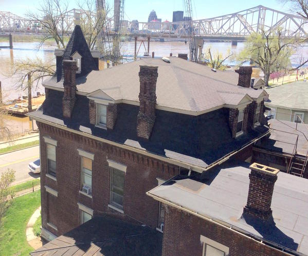
Vanderbilt inherited $10 million from his grandfather which is over $280,000,000 in today's dollars and that may not be enough to re-create Biltmore even if you could find extant Italian stone masons to carve all that limestone. As it was, it nearly bankrupted him. His widow sold 117,000 acres to the Federal Government which became the Pisgah National Forrest to help pay his debts.


My Victorian station cost over $200 in raw materials and that was completely in styrene. I'm planning on retailing a kit of the distillery and I'm working to bring the overall costs down a bit so it's affordable. I can see why B.T.S' entire sawmill complex will cost you over $3,000 to buy the kits.

Back to the Distillery pilot. I finished all the trim work today making (and re-making) styrene trim (that will ultimately be more laser-cut parts). My scribing in no way duplicates the beauty and regularity of the laser etching. It reinforces the decision to have the model laser cut in the first place. I changed the way I was cutting the "eyebrows". Instead of making them curves to follow the lintels, I selectively took out "bricks" to square it off. Bricks wouldn't be trimmed in such a curve. They're more like pixels in that regard.


I'm now at a point where I can make all the drawing corrections on the kitchen and the main building for the production version. I'm still going to have to build the main building pilot to give myself the level of assurance that I now have for the kitchen. I waiting on a shipment of corrected parts for the main building. But meanwhile I'll finish up the kitchen. I have a left over Grandt Line chimney that I'm going to put on this building.


Here's the four sides before priming.


IMG_3411


This view clearly shows the notches above the lintels.

IMG_3412

IMG_3413

IMG_3414


After dinner I took the kitchen and connecting corridor outside to put on the Rustoleum brown primer. This is the same color I used for the fire house. It's very hot here tonight and there was a breeze that kept changing directions. Every time I thought I was spraying with the wind I wasn't. This will dry over the weekend and then I'll give it another sealing coat of Dullcoat. I found that the joint compound dissolved some of this paint on the fire house and to avoid that I'm sealing it again with a non-water-based product. I'll still use the alcohol wash as before.


IMG_3416


It looks overly red in the sunshine. It's more brown than that in person. The parapet tops of all the walls will need some capping tiles. I'm going to use styrene for this to simulate the stone that would be used in this instance. The reverse side of the Masonite is not smooth. Some of this parapet wall will show after the shingles are in. I'm going to simulate tar paper going up to the capping to cover it. That's not so far fetched. Lots of roofs are made like that.


I was going to glue the corridor onto the kitchen. I had it fitted and even had my clamping procedure down. Then I realized that it would make getting its two windows installed much more difficult. But I needed to check one thing first. Could I get that roof on with the corridor in place. I tested the theory and, yes, I can easily slip the roof down the groove into position. So, installing the corridor will have to wait until all the windows are in place. Again, that's why I'm making a pilot. I'm going to have to create instructions for this as a kit and it needs to go together without undue complications.

Attachments

Images (5)
  • IMG_3411
  • IMG_3412
  • IMG_3413
  • IMG_3414
  • IMG_3416

And one more thing.


There is a stained-glass window in the transom of the kitchen door. I googled "Stained Glass Transom Windows" and found many to choose from and several in the same proportions of the model. I copied the images, imported them into Adobe Illustrator and then shrunk them to fit the door opening. I first used an enlarged image of the opening to shape the image to fit and then reduced the images to fit the opening.


Screen Shot 2015-06-12 at 8.59.43 PM


I printed this image out on transparency film and will cut them out to go into the opening. I'm going to use 0.010" clear styrene as glazing. This will be put on top of that 'glass' to give it some body. Transparency film is rather flimsy. This image is not to scale. The real window is very small. I printed out several styles to see which one will show up best with the backlit LED lighting.

Attachments

Images (1)
  • Screen Shot 2015-06-12 at 8.59.43 PM

The 1870s was the golden age of machine design. Mankind was enamored with the newly emerging industrial age. Just look at the beauty of the old stationary steam engines. At the Children's Museum of Philly there's a model of the 1876 Centennial Exposition. The buildings and machines inside were fabulous and highlighted the upcoming power of the USA. Memorial Hall was preserved and is now the Children's Museum which is a wonderful re-purposing project. Humans were able to both work with machines AND be interested in the Humanities. Unlike today, if you like machines, you certainly can't be erudite. Wrong!
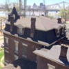
 

Memorial_Hall_Phila


All of the buildings looked like this one. I'm glad that Philly didn't raze this one and eventually made it do some wonderful things. Anyway, they are not easy buildings to model. 3D printing, as it improves and gets cheaper, will allow us modelers to make more ornate structures for our towns if we do desire. When in Asheville we took some pictures of the downtown buildings. One on a corner was from the early 1900s and WOW! It even had gargoyles!


FullSizeRender


And the less tall one next door was no slouch either. Like the substation project sparked my interest in power distribution, the fire house and now the distillery is firing up my architecture genes. The nice thing is that my wife can really appreciate the buildings, much more than locos and rolling stock.

Attachments

Images (2)
  • Memorial_Hall_Phila
  • FullSizeRender

It's Monday, so I'm back in the shop.


I did a trial by using the joint compound directly over the Rustoleum paint which had 3 days to fully cure, and then I shot some Testor's Dullcoat and then used the compound. It did reduce the "red bleed" from the paint to the joint compound so I took it outside in the summer heat and sprayed the whole building. It was so warm that it dried almost immediately.


After applying the compound I cleaned off the excess with a damp paper towel and then used some alcohol/India Ink wash. Here's what it looked like. The right side is un-wiped compound, the middle is the washed area and the left is wiped compound. 


IMG_3427


My wife likes the un-ink washed brick, but this is a factory and would not have brightly pointed new brick work. I like the dull subdued appearance. Notice that the hand-scribed styrene brickwork is not as regular or as deeply engraved as the laser-cut bricks. Also notice that I drew the bricks with "common bond" where every 6th row shows brick ends. When buildings were all masonry, they used double-thickness brick walls. The bond course was facing inwards to tie the front and back walls together. It also makes nice patterns. With laser-cutting, the design is whatever to can manage to draw.


Here're the other views. The crenelations are the hardest to get the joint compound properly applied.


IMG_3430

IMG_3429

IMG_3428Even with the Dullcoat, I was still getting some pink bleed, but not enough to stain the "mortar" pink.


IMG_3431


Just as a reminder, here's the Joint Compound that I'm using. It's very fine grained which works for O'scale projects.


IMG_3433


I sent André a new set of correction files for the main building. For this iteration we made two adjustments. We decided that PDF versions would work better for him since he's using CorelDraw and I'm using Adobe Illustrator. The PDF conversion looked very clean. I also drew the images on larger "art boards"—the work pages on which you draw using Illustrator—which enabled me to now draw in a single piece the building's ends and floors. The production drawings for the kit will have all the big walls as single pieces. Since I've already glued up the side walls I didn't need to have them re-cut at this time.

Attachments

Images (6)
  • IMG_3427
  • IMG_3430
  • IMG_3429
  • IMG_3428
  • IMG_3431
  • IMG_3433

Thanks André!


It keeps getting better. Today I finished the joint compounding of the front. It took quite a while to apply, and even more time to remove the excess. I'm really feeling like a dentist removing plaque. I'm using the same instruments. I reground the ends of some of the probes to give flat scraping edges that could get into the corners and clean out the excess dried joint compound.


IMG_3436


The grouting must makes the brick design pop. After going over all the corners and flat areas I gave a two layered wash with alcohol/India Ink to dull it all down. If even got too dull in parts so I went back over it with a water/alcohol mix to remove some of the black. Here's the end result. The capitals topping the crenelations will be painted concrete color.


IMG_3438


I decided that the front door needed to be stained and not painted since it's actually wood. I had some MinWax dark walnut stain and put on two coats. It has to dry 8 hours before doing anything else. I may still add some more stain to darken it some more. After final staining I'll coat it with some form of clear coat.


IMG_3435

Lastly I needed to make roof parapet capping. I chose to do this out of styrene for the pilot. I'm going to have them laser cut out of 1/16" Masonite for the production version. After measuring, cutting and fitting I airbrushed them with Model Tech concrete acrylic. I'm waiting until the roofs are in place with shingles and tar paper before final installation. You'll notice in this picture that the roof trusses were notched for purlins. The roof pieces, being 1/8" Masonite, are so stiff that the purlins are unnecessary. I've removed them from the drawings for the production version. As I'm writing this, I'm thinking that they would provide a convenient anchor for the LED lighting. Hmmmm.


IMG_3439

IMG_3440


The front pieces are notched to clear the corner brick towers. Tomorrow, i'll airbrush the window frames, finish the front door, and make preparations for the lighting.


I'm not going to use the 3-light set that I used for the fire house. It's just too big and bright for this small space. Instead I'm going to use a single LED. I may even dull it down some more by wrapping the bulb with frosted Scotch Tape, or painting the LED with some Tamiya clear yellow. This building wouldn't have been lit with florescent lighting so the LEDs have to be a little subdued. For the main building I'm probably going to use the big LED strips, but maybe put color filters over them to again make them more yellow and less blue. As I'm thinking about this I realize that the kitchen lighting should be tied into the main building lights so there's a single lead to tie into lighting power.


I'll also paint the concrete details on the building front. Those capitals probably were limestone, so I may add a little more white and yellow to the concrete color to lighter it up a bit. I have a Model Tech sand color that may work better. I test it before finishing it.

Attachments

Images (5)
  • IMG_3436
  • IMG_3438
  • IMG_3435
  • IMG_3439
  • IMG_3440

The kitchen is turning out nicely!  You do have a point about leaving the purlins in to hang lights.  Hanging from the bottom of the truss may be too low and show through the window! and hanging from the top of the truss may cause a funny shadow where the truss bottom blocks some light.  I never knew what those pieces were called.  I like the wood grain on the door.


What are the overall dimensions of the whole distillery building?  I take it that it is larger then the firehouse by a good bit.  If you already mentioned it I missed it skimming back through the topic.  Lots of pieces.

Mark,


The way it was configured in my original drawings makes it 34-1/4" wide by 43-1/4" deep.


 Screen Shot 2015-06-17 at 6.56.34 PM


But, that's including the warehouse and silos. If you choose not to build those, it would be 16.5" deep by 34.25" wide. Right now, the kitchen is attached to the main house as it appeared in the original photograph. The building to the left, the boiler house, is my own design and hasn't even been drawn yet. I myself may not use it on my layout in this configuration. I may choose to move the warehouse to one side or the other. I still haven't decided on how to make that big chimney or the silos. Just having the main house and the kitchen would make a really nice model.


Speaking of nice models, here's today's report.


I installed the purlins based on Mark's suggestion.


IMG_3444


I also hand painted the capitals on the front brick work. It took two coats of Model Tech concrete.


IMG_3441


 I then airbrushed the window frames a Model Tech Pennsy Green color which seemed appropriate for a factory setting. Model Tech is almost completely odorless and dries very quickly. I help the drying by using a Top Flite hot air gun. The plastic paint bottles use the same thread as the Badger bottle adapter on my airbrush, so I can just screw the paint bottle on and start spraying. I shoot it un-thinned straight from the bottle. I believed Walthers carries the full like of Model Tech colors. It goes on nice with a brush too.


IMG_3443


i put another layer of walnut stain on the main door too.


Lastly, I started shingling the roofs. As I noted yesterday, I purchased Rusty Stumps Victorian Slate collection which has an equal amount of straight and fish scale shingles. You alternate three rows of each. After drawing guidelines on the roof I started applying the self-stick shingles. They stick very well on the smooth Masonite and didn't need additional adhesive. I let the lowest row of shingles overhang the roof a bit so they'll cover up the top edge of the brick trim pieces forming the eaves.


IMG_3445


After trimming here's what the first roof half looked like.


IMG_3446


Pretty spiffy, eh? I don't intend on gluing down the roofs. They fit very snuggly without it. It may be difficult to remove them though once all the windows and doors are in. There will be chimney on one of them that could form a convenient handle to life one side. With LED lighting, I doubt there will ever be a reason to open it up.


Tomorrow I'll do the second roof half and install the lighting. I will also use "tar paper" roofing for the corridor. I'm going to tar paper the unfinished Masonite that forms the interior of the parapet. And I'll be ready to start installing windows. I neglected to design the loading door in this pilot cutting. I've since added it the production file. In this case, I will scratch-build one. It's not a big deal. I'm also thinking about adding downspouts and gutters following the same scheme that was used on the fire house. Bar Mills never includes these in their kits, but for a formal structure like this one, I think they're needed.

Attachments

Images (6)
  • Screen Shot 2015-06-17 at 6.56.34 PM
  • IMG_3444
  • IMG_3441
  • IMG_3443
  • IMG_3445
  • IMG_3446

Thank you.  I didn't realize there were as many supporting structures.  Maybe I missed something.  No matter.  Yes it is a big complex, even on a layout the size of yours.  


The kitchen is turning out great.  The concrete capitals and the Rusty Stumps shingles really add to the overall good looks.  Yes, I think that green on the windows is appropriate for this building, having seen that used in the past.


it will be great to see how the main building turns out!

The supporting structures are really optional. It's really a chemical plant. Chemicals that you can drink. The kitchen is even exceeding my expectations.


Today I finished roof #2, got the lighting installed and then attacked the door and windows. 


The first thing I did was turn a door knob. It ain't a door without a knob. I started with some 1/8" brass rod and turned the end down to a little over 1/16". I then used a tool which I had already ground a nice radius to form the front of the knob. I used a very narrow parting tool (also custom ground) to shape the stem down to something much smaller. The size isn't critical as long as i had a jeweler's drill in the neighborhood.

 IMG_3450


The stem turned about to be a #37 drill. I drilled the hole, inserted the knob and then used thin CA from the back to hold it in place. I also glue the window frame from the back using Aleen's glue, and then installed the "glass" (.010" clear styrene) using the liquid Pressure Sensitive Adhesive (PSA), and then installed the stain glass window. Before fastening in the stained glass I first installed a piece of clear styrene which gives the transparency film something to hold onto. I used a few drops of CA to hold the transparency to the styrene. 

 IMG_3452

As i noted earlier, the production version of this kit takes care of some errors that I made in the initial design. This pilot is using parts in the first cutting. One of things I quickly realized is that the windows and doors need more than just a piece that fits perfectly in the opening. They need some support to hold them into the opening. For the Production version, I've added another layer that extends past the doors and window frames and holds them to the rear of the opening. For this pilot I had to add separate pieces to frame out the back of the door. It also blocks the excess light that would sneak out around the frames.

 IMG_3453

Before going further with the windows, I needed to get the lighting in place. Once the windows are in, it would be more fragile and handling it would be problematic. I'm using one single LED and I attached it to the purlins. I sawed a couple of notches in the purlins so the roof would close down tightly against them. I hooked up the LED, soldered the red and black leads to the + and - leads, and ran the wires out of the extra hole in the side (the one that was an error in the first drawing). I couldn't wait to light it up and hooked up the 12VDC source. Nothing. Reversed polarity and still nothing. What's wrong? Any ideas? Well... I'll tell you what's wrong. I did it again. In my haste to see if it lit, I forgot to install the 470 ohm current limiting resistor. The LED never had a chance. It blew out without even a whimper. I got another one, this time adding the resistor and the light worked perfectly.


Here was the first one mounted on the purlins.

 IMG_3454

That was the LED I blew out. Here's the installation complete.

 IMG_3455

 The LED is secured to the purlins with some CA.


I added some shrink tubing pieces to the leads coming out of the building to keep them ship-shape. They'll tie into the lighting leads in the main building giving only one connection.


 IMG_3456


With the light done and checked (it worked!), I started on the windows. Because of my inexperience, my first designs for the windows were incomplete. I missed two key features. First, I didn't allow for any material to which to glue the bottom (inside) sash. Second, I didn't allow for any support to hold the windows in place and aligned.


So in this case I improvised by adding some of the same 1/32" ply stock (edges of the windows fret) to make side supports. I also added the supports just to the lower sash area to space it backwards one window-thickness thus allowing the lower sash to lie behind the upper, and, in the case of the front window, enable me to position the window open. In the production drawings this is all corrected making the parts look more like they should. Since this is an all masonry building the windows are inset into the walls. If it were a frame structure, the window designs would be reversed, more like how Bar Mills does their's.


IMG_3457


I glazed the windows with the 0.010" clear styrene. For the windows I'm using three different kinds of adhesives: CA for to hold all the sash pieces together, Pressure Sensitive Adhesive to hold in the glazing, and Aleens PVA to hold the windows into the building. I use Chobani Yogurt cups turned upside down as glue receptacles. In this case, I put blobs of each type on one. Having them raised above the work surface makes it less likely that I will lay something in it, or get my hand on it. Notice I said, "unlikely", not "impossible". With me, nothing is impossible.


Here's the front window installed.


IMG_3458


Here's the back view showing the extra material that's supporting the window.


IMG_3459


A little bit of light can still leak out around the upper sash so I may just glue a piece of black construction paper butte up against the window to block that little gap that still exists. I did the same thing on the top of the door.


Here's another view showing the relief better. Those laser-cut bricks sure look good!


IMG_3460


I could have made the curved lintels above the openings as part of the brick design. Instead I close to make it a separate piece so it's proud of the surface. I've seen buildings both ways. Any one have any opinions... not for this structure, but future ones?

Attachments

Images (11)
  • IMG_3457
  • IMG_3456
  • IMG_3458
  • IMG_3459
  • IMG_3460
  • IMG_3450
  • IMG_3452
  • IMG_3453
  • IMG_3454
  • IMG_3455
  • IMG_3456
Last edited by Trainman2001

Finished all the window installations and worked with both grandkids on their last day before heading off to overnight camp. #1 grandson wanted to take apart an old RC flying machine and use the motors and props as a fan he could use at camp. He's learning something about electronics at school and was anxious to see what voltage/resistance was needed. We ended up using an old throw-away flashlight as the battery holder. He then wanted to use one of my LED strips to make a reading light. I gave him one of my spare 12vdc converters and in a few moments he had one powerful light.


So grandson #2 wanted to do something two. He's 11. He ran the trains a bit and I videoed him. Here's a short clip of #2 running the trains today.


https://youtu.be/vFfh1jSw5XY


So he wanted to make an LED flashlight. We found an 9-volt battery holder in my electrical stuff, a 5mm warm white LED, and then I showed him how I find out what size current-limiting resistor should be used. So then we had to build a container. I use those Chobani Yogurt cups for all sorts of things and now we turned one into a flashlight: a Chobani LED 9V flashlight. We made a plywood disk to close the big end, cut open the small end, and then mounted a SPDT switch that was fastened through the containers side with a ply backing plate and some small machine screws and nuts. The big end was held with miniature self-tapping screws. The small end was hot-glued which contained the LED and an LED socket. We covered the outside of the small end cover with aluminum foil, and then screwed a clear plastic dome that was left over from an old robotics project that my son built when he was their age. He's now 40! In fact that robot has been put to some good use. The motors and gear sets were used in Grandson #1's Rube Goldberg Project two years ago.


They were both really pleased with their work! Starting out with some junked toys and some electrical parts, they both ended up with cool, usable stuff. Good way to send them off to camp.


I also glued on the parapet caps. Next session I'll be working on the chimney and roofing the corridor. I ordered some metal from Special Shapes to make downspouts. I bought brass square channel for the gutters and copper tubing for the downspouts themselves. I wish they stocked the square channel in copper too since that's what these spouts would be. I'll only have to paint the brass parts now.


IMG_3463


By the time I get the kitchen finished, André will probably have the corrected parts for the main building done and then the real fun will start. This was just a chance to hone my skills some more. I was especially glad to have the opportunity to try the brick coloring techniques and how realistic it came out.

Attachments

Images (1)
  • IMG_3463
Last edited by Trainman2001

Well... word is they both got to camp safely and have been assigned bunks. With modern technology we get photos every day so we can see if they're eating, using sun screen, etc.


Today I exercised on the equipment and got in a couple of good hours of work on the distillery kitchen. The roof ridge material arrived from Rusty Stumps and I was able to finish the roofing on the building and also did the corridor.


For the corridor roof I used left-over "tar-paper" self-stick roofing material from Bar Mills. I put it on with about 1/8" overlap. I measured the distance between the parapets with the calipers, transferred the marks to pre-cut lengths (I made one first to determine how much material was needed and then cut them all with the Chopper) and then scored across the piece on those marks.


IMG_3464


Since the tar paper is self-stick I didn't need to apply anything to the roof base, but the sides are that un-finished Masonite and needed a little more so I brushed on some PSA liberally to provide more stick. I then applied all the pieces.


IMG_3465


With a nice new sharp razor blade I trimmed all the excess flush with the parapet top. I then painted the tar paper Tamiya Nato Black (a weathered black) with two coats, applied the painted styrene parapet tops with RC 550 canopy glue, and then added some gloss black sealing "pitch" to seams. I will add some weathering powders to both roofs later. But for now the two buildings are essentially complete except for the chimney and loading door. I'm going to scratch-build the loading door for this pilot only. It's being laser-cut on the revised cutting plan.


IMG_3466


I took some beauty shots under natural light outside. There are no pictures of the back since that load door is just a big square hole. On the inner parapet I used black construction paper notched like counter flashing and the doctored up with glass black "pitch" again to cover the unfinished Masonite. On the main distillery building I'm going to have some thin stock brick-etched overlay material to create an inner brick facing on the inner parapets. On this little building I chose to just use the flashing. 


IMG_3468


For comparison, here's the original SketchUp drawing upon which the building was created.

 Kitchen Final SU Pic0016


The Rusty Stumps shingles really came out nice. You can clearly see the peak capping in this picture. 


IMG_3469


In the revised drawings I've also closed down the opening where the corridor meets the kitchen. On this pilot, I'm not going to worry about it. Where it's going to the layout it won't be too noticeable.


IMG_3470

Attachments

Images (7)
  • IMG_3464
  • IMG_3465
  • IMG_3466
  • IMG_3468
  • IMG_3469
  • IMG_3470
  • Kitchen Final SU Pic0016

Thanks all!


That cantilevered front embellishment repeats itself, only large and more grandiose, on the main building. It was difficult for me to visualize and align in SketchUp, and then equally challenging to engineer so it would "hang" at the proper orientation.


Today I finished the chimney using a left over Grandt Line unit that I had. I made a styrene "concrete" support that was cut at the roof pitch and the chimney sits on top of that. I chose a quick-and-dirty method to do the grouting; I sprayed the whole deal with Model Tech concrete, forced dried it with the hot gun, a coat of Dullcoat to seal it and dry brushed a mixed Tamiya blend to resemble the color of rest of the brick work. The results are okay, but not up to my standards. I think the chimney is too big for the building. For the production version, I'm going to come up with something else.


IMG_3471

IMG_3472


IMG_3473


I still needed a back door. I used the same plans as I sent River Leaf for the laser cutting to cobble out a door using two layers of styrene. The backing with the scribed planks is 0.040" styrene, and the overlay is 0.010" styrene. I used Krylon spray adhesive on the paper plan and stuck it to the overlay styrene and cut it out using the Xacto.


IMG_3474


Tomorrow I'll air brush it the same green as the windows and install it. Boy! You can really appreciate laser cutting when you have to hand-build something as simple as this door. It took close to an hour to scribe all the lines and cut it all out. As a laser cut part it would take less than 5 minutes to assemble and look much better.


I will then glue the corridor to the kitchen and this phase of the pilot is complete. I'm waiting for the corrections cutting to come from River Leaf. We're leaving for an extended 11 day trip on Friday, so work will come to a halt then and resume when I return. My singing 10 year-old granddaughter has a singing lead in a professional production of Les Miserables in State College, PA and we're going to see her perform (among other things).

Attachments

Images (4)
  • IMG_3473
  • IMG_3472
  • IMG_3471
  • IMG_3474

After exercising late, I did get some shop time. Got the load door painted and installed, but a front step and decided to fill those gaping holes in the corridor walls. All of these annoyances will not be part of the production version (there may be other annoyances, but not these).


I used the same Model Tech Pennsy Green for the door and then sealed it with Dullcoat since I may want to use an alcohol wash and didn't want the water-soluble green to be disturbed. Before installing I cut some scrap green-painted pieces of the 1/32" ply and CA'd this to the back of the door opening to prevent the load door from falling inwards and to provide a good gluing surface.


IMG_3475


I then CA'd the door into this space. The strips are wood, the load door was styrene so CA was glue of choice. I neglected to paint the white interior side of the door. This is now seen when the interior is illuminated. On the production version, this door's back sheet will be wood and may not need to be painted. The overlay trim will be laser board.


Here's the installed door.


IMG_3480


The prototype picture showed a front door step. I added this using a thin piece of styrene sheet as a backing to cover the brick and a 1/8" x 3/16" piece of styrene rod for the step. The backing sheet was CA'd to the building and the step glued using solvent cement. I then brush-painted it with Model Tech concrete.


IMG_3477


Finally I decided to make fillers for those gaps. I made a pattern out of styrene of the opening's shape and transferred this to a piece of the main building that is now scrap since I've re-designed the parts to be single pieces instead of the jig-saw puzzle's pile that I originally had cut. After River Leaf Models helped me understand that he could cut larger pieces on his machine, I was able to build all the walls and ends with full-sized parts.


IMG_3479


I attempted to match the bricks for the patches. I did so... marginally. Again, the gap will be closed with a re-designed part in future models. I cut the first piece on the jig saw, but wasn't happy with how that went. The next piece I cut using the fine-toothed razor saw. After sanding I got them to fit the spaces. Aleen's and CA hold the pieces into the wall. 


IMG_3478


The last thing I got done was putting a coat of Rustoleum primer on by brush. I decanted some of the spray can into a Chobani Yogurt tub. 


IMG_3481


Tomorrow I'll use a little joint compound, some alcohol wash and hope that it won't be too un-sightly. As I used to tell the kids in shop class, "There's always time to do it over, but never enough time to do it right the first time."


I doing similar brick work on the engine house design. The bricks in Adobe Illustrator put a huge demand on system resources. Each vertical line is a separate entity and the horizontal lines aren't one object all the way across either. They're multiple lines due to how I built up the brick array. I now do the bricking fairly quickly by copying a sheet of them and use the "Draw Behind" feature to place all the bricks within the outline of the wall. I'm not done yet. Since the laser cuts any line that 0.3 points, and engraves lines that are wider, e.g., the brick lines are 0.7 points wide, any where that a brick line is overlapping a cut line would turn the cut line into an engraving. So I have to go back and remove any interfering brick lines that hit edges, windows or doors. This is tedious, but not as bad as it was when I had to adjust all the bricks to lie within the image's confines.


The file size was so onerous that there was a one or more second delay every time I clicked on something. I finally split the drawing into three separate files and sped every thing up nicely.

Attachments

Images (6)
  • IMG_3475
  • IMG_3480
  • IMG_3477
  • IMG_3479
  • IMG_3478
  • IMG_3481

Mark, the engine house looks like this. I just cranked this out in SketchUp based on the line drawing that I made. It's 41" long and has three tracks spaced 3.5" C-to-C distance which is the spacing of the Ross #4 yard switches when arranged in the ladder scheme.


Screen Shot 2015-06-25 at 1.37.20 PM


if I get it laser cut and I'm drawing it for that application, it will have similar levels of brick detail. Since it's over 40" long, I'm doing the sides, floors and roof pieces in twos with joints between them. There will be loads of laser-cut windows, and several man-doors. I'm also designing a mechanism to open all three doors remotely. This length is necessary to hold my longest steam engines. it will be the biggest engine house out there. Most of the other kits are all half that length and work for single unit diesels. For those of us with large steam you're left with two choices, build your own or buy one of the larger roundhouse kits out there, but what if you can't sustain a 32" turntable? What do you do then? You build a straight house this large.


I've also detailed a traveling crane for the ceiling in the 100 ton range. It will require some more elaborate interior framing. I'm using roof trusses like I did with the distillery.

Attachments

Images (1)
  • Screen Shot 2015-06-25 at 1.37.20 PM

It certainly won't be for everyone... I may not offer it unless there's interest. But I do need it for my pike.


I cleaned up the patch on the corridor walls and attached the corridor to the kitchen. I used my longest clamps and put a wood block across the opposite side of the kitchen so the clamps wouldn't wreck anything.


IMG_3483


After about a half hour I unclamped the parts and got a nice nice joint as a result.


IMG_3484

The patch, now that it's been given the mortar treatment ins't so objectionable. It looks like someone actually made a brick repair to the building. Regardless, it's going to be hidden mostly by the gutters and downspouts I'm adding. Speaking of G & Ds, I started construction today.


The square channel has an i.d. of 3/32" so it just fits the 3/32" copper tubing I bought. I'm using two different melting point solders (again!) so I can solder one part and then solder another nearby without losing the first. I'm also including hanger pins so I can pint the gutter to the building and give it a little more support than just gluing it...just like in prototype practice.


IMG_3485


My only regret is not being able to get copper channel to go along with the copper tubing. After I paint it with the primer and copper paint, and then the patina, you won't see too much difference. I wish I could get the brass copper plated... I'm sure there's something in Louisville who could do it.


At Michael's yesterday I bought some more artist's brushes and then saw this pack of palette knives that would be perfect tools for smearing on the joint compound on all this brickwork. It was very cheap. I've been using styrene scraps and pieces of wood. This seems more elegant.


IMG_3482


We're off on our trip tomorrow so, dear readers, you'll have to wait until after the Fourth to see the rest of the distillery project come together. André finished cutting my corrections for the big building and I'll have it in my hands upon our return. So I'm finishing the kitchen at the right moment. All I have to do is finish the gutters and it's finished.

Attachments

Images (4)
  • IMG_3483
  • IMG_3484
  • IMG_3485
  • IMG_3482
Originally Posted by Trainman2001:

Mark, the engine house looks like this. I just cranked this out in SketchUp based on the line drawing that I made. It's 41" long and has three tracks spaced 3.5" C-to-C distance which is the spacing of the Ross #4 yard switches when arranged in the ladder scheme.


Screen Shot 2015-06-25 at 1.37.20 PM


if I get it laser cut and I'm drawing it for that application, it will have similar levels of brick detail. Since it's over 40" long, I'm doing the sides, floors and roof pieces in twos with joints between them. There will be loads of laser-cut windows, and several man-doors. I'm also designing a mechanism to open all three doors remotely. This length is necessary to hold my longest steam engines. it will be the biggest engine house out there. Most of the other kits are all half that length and work for single unit diesels. For those of us with large steam you're left with two choices, build your own or buy one of the larger roundhouse kits out there, but what if you can't sustain a 32" turntable? What do you do then? You build a straight house this large.


I've also detailed a traveling crane for the ceiling in the 100 ton range. It will require some more elaborate interior framing. I'm using roof trusses like I did with the distillery.

I'd definitely be in for the engine house!

Hey gang, I'm back!


The engine house won't get underway for a while. I still have to build the rest of the distillery pilots, and then I think I'm going to build the tunnel/mountain on the undecorated side of the railroad.


We got back Monday after driving straight through from St. College, PA, so I lacked the enthusiasm to get downstairs and work. But I got there today.


I finished soldering up the rest of the gutters/downspouts, masked the copper parts and primed the brass gutters. After drying I painted a few coats of craft paint copper and forced it dry with the heat gun. Before painting and handling them, I marked the locations of the mounting pins and drilled the kitchen walls with the 0.021" drill. I first tried it with the Dremel, but found better luck using the little Archimedes jeweler's drill. After testing the fit I did all the painting.


To age the copper I again used the Rub-n-Buff patina cream. Funny... it actually worked better on the painted brass gutters than the real copper downspouts. I had to work to get enough patina on the copper to look right. Otherwise, I had old looking gutters and shiny, new, copper downspouts coming down from them. I have a lot of this 3/32" copper tubing so I'll be facing this little blip for some time now. I then added some weathering powders to the roof and with that, I'm declaring the kitchen part of the distillery complex complete.


Kitchen Finished 01

Kitchen Finished 02

Kitchen Finished 03

Kitchen Finished 04


The following two pics show the other side gutters in place for test before the patina was added. The copper paint on the gutter does closely match the color of the real copper downspouts. Unlike the firehouse, where I attempted to attached the gutters using those contact cement dots, I soldered pins through the gutters in prototypical fashion, and they're glued into holes in the building.


Kitchen Finished 05

Kitchen Finished 06


I used the time remaining to clean up the shop a bit and get ready for Andre's next shipment which should arrive any day now. 

Attachments

Images (6)
  • Kitchen Finished 01
  • Kitchen Finished 02
  • Kitchen Finished 03
  • Kitchen Finished 04
  • Kitchen Finished 05
  • Kitchen Finished 06

Thanks All!


Right now, I'm discussing With Andre Garcia of River Leaf Models to jointly offer the distillery as a kit for sale. I'm in the process of writing the instructions, which is a project unto itself. After that, I'd like to work with him to offer larger, more complex and rare models. My company name is Hi-Tech Miniatures, but will work with Andre at River Leaf to make products available sooner. We're a few months away from any final decisions. Andre's offerings of nice brick structures fits my strategy perfectly. With the advent of Laser-cutting and great design software, it opens up a whole new avenue to produce heretofore unchosen subjects.

If there's to be another firehouse, I'll have to take Les Lewis' design and convert it to a laser cut kit. It shouldn't be too hard since it's simpler than the distillery. Let's take one thing at a time. I don't even have the distillery pilot model completed.


On Friday I did some work on the Distillery even though I haven't received Andre's latest shipment. I needed to make resin casting masters for the stacks and ventilators. For the stacks, I took 3/16" brass tubing and turned tapered rain caps for them. It was a simple turning job. I also made a small tapered base for the tall stack that engages directly with the roof.


IMG_3590


The fit was so tight at the top that I simply made a press fit.


For the ventilator, I made it in two parts to accommodate the deep-wide smaller diameter. It's hard to machine against a right-hand shoulder. Of course, if I would have thought a little bit more (which I'm now doing as I write this), I would have machined the step first, turned it around and then machined the taper. As it is, I got right into matching the taper and this didn't leave a lot of stock to grip if I then turned it around to turn the step.


IMG_3581


Here's the two-part vent before fitting together and holding with CA.


IMG_3589


To part off this work piece, I had to lengthen my self-made cutoff tool. My first attempt at grinding all of that hi-speed steel created a tool that was so thin that if I tried to make a cut up to a step, the tool was bending sideways instead of cutting straight ahead. I then did another one this time leaving enough thickness so the tool worked as it should. Obviously the correct one is on the right. In both cases, for cutting aluminum, I made a little trough behind the cutting edge to provide positive rake to help curl the chips and cuts with a knifing/slicing action. For brass, the top of the top actually pitches forward (negative rake) so the tool cuts by scraping rather than slicing. Brass is soft and if you try to slice it, the tools digs in and jams making a mess.

 IMG_3587

I didn't cut the diagonal base to conform to the roof pitch. I really don't have the holding fixtures for my lathe milling attachment to feel comfortable cutting it. Instead, You can just cut circular hole in the roof perpendicular to the building's baseline and glue it in. Alternatively, the resin part will be much easier to cut than aluminum and that may be easier to do than cut the angular hole in the roof. I'll wait until I build the pilot to see what's the best way to approach.


I ordered new resin casting supplies from Smooth-on and sulphur-free modeling clay from Amazon to cast the parts for the kits. I've also officially started writing the instructions for building the main building and the kitchen. The Smooth-on website made it very easy to choose the correct silicone, resin and release agents for my application.

Attachments

Images (4)
  • IMG_3590
  • IMG_3581
  • IMG_3589
  • IMG_3587

Everything arrived today! The resin materials, the clay and the replacement parts from River Leaf Models. I immediately started constructing the main building. I already found some errors, but I can work around almost all of them for the pilot. I've already modified the production drawings (again!) to reflect these new 'discoveries'. i won't submit the final set to Andre until I'm as sure as I can be that it produce the model correctly without any fudging on the part of the builder.


Here's the building slapped together without glue to get the fits and sequencing down. 


IMG_3592


The un-sightly seam on the side walls is already eliminated on all future cuts since it will be done on larger pieces like the new ends in this picture. I had Andre re-cut the ends because there were other errors in them. Since the side walls were okay other than the seam, I'm keeping this pilot for myself. Normal buildings don't have that intermediate wall that divides the building, but this one does since the upper clerestory part ends at that mid wall.


There is brick trim for the un-bricked back of the Masonite. The gap for the roof piece is too wide, and I'm fixing that on the next go around. For the pilot, I may just raise the trusses a bit to push the roof about 1/16" higher.

 IMG_3595


I found that the floor support frames were incorrect, but I had already noted this when I went back and re-checked all the drawings the last time. I had used the same frame for the second floor support and for the roof trusses. This was wrong since the first floor ceiling height is higher by a couple of scale feet. I made some supports to hold the 2nd floor frames to the correct height. But this too is corrected on future versions.


There were some minor discrepancies concerning the trim pieces. Since I ordered these re-cuts I revised the way the trim would be mated at the corners. By using a bevel, I had to extend the width of the corner trim on both parts by one material thickness (1/16"). By beveling the corners it is possible to have the bricks meet prototypically instead of seeing the end grain of one of the pieces of 1/16" ply.


IMG_3596


The only thing I need recut to finish the pilot (as I can foresee at this time) is the multi-layer crenelations layers which I mistakenly had cut in 1/8" stock instead of 1/16". It's just a little job which I hope Andre can turn around quickly. I won't need it for some time since getting the rest of the building done will take some time.


I found that the tabs on the floor piece (now one piece) to be 1/32" too deep and stuck out from the wall panels. This is not a big problem since you can always remove excess stock. This was a piece that I forgot to change after Andre informed that the 3/16" Masonite is actually .155" instead of .187. I've been revising all the tabs and slots to recognize this change, but I missed that one. Details, details!


I'm writing the instruction set and it should be pretty comprehensive. Here's a sample of the images I've created in SketchUp for the booklet.


Kitchen Construct Draw 01


Since I have the SketchUp master drawing, I have all the raw material to make many of the detailed construction views. I'm doing the kitchen instructions first since I've completed that pilot. I'll be writing the main building instructions as I proceed with my own build.

Attachments

Images (4)
  • IMG_3592
  • IMG_3596
  • IMG_3595
  • Kitchen Construct Draw 01
Originally Posted by Trainman2001:

I don't know yet. About all I can say is over $500.00. We haven't had a complete production cut yet so I don't even know what the raw material and manufacturing costs are. It will be fairly priced for a complex, very handsome model of a rare prototype.

Hi Trainman and Andre, 


These are high quality works, so I would not dispute the price point, but it is a risk for a first time venture. I would have hoped for something smaller as a buy in and move up from there. Perhaps, the fire house I so want so bad would have been less expensive? (hint, hint)


Cheers,

-r


Andre's River Leaf already produces a very nice line of modest kits. I'm offering this as a not-so-usual, more elaborate one. I can also think about building the fire house kit, but it too has a lot of ornamental brick work that constitutes more time on the laser cutter and therefore more $$$. I'm looking to produce special, unusual and interesting models and Andre is going to help me do that. It's all very new to me so we'll see what happens.


Today I began construction of the main building starting with gluing the mid-partition wall, followed by the two rear side walls and then the rear wall. I used Aleen's tacky glue to hold it all together with various clamping schemes and right angle blocks to maintain square. 


IMG_3605


IMG_3606


IMG_3613


I like those corner clamps. I only have two of them and should buy more. They provide good grip and keep things square.


The windows will have to go in from the inside. This means that installing the second floor has to wait until the windows are in. This means that all exterior painting and grouting needs to be done before windows and floors get installed. That's why I'm building a pilot before writing all the instructions for the kit.


While this was drying, I turned my attention back to that ventilator master. I wanted to try and put the bevel in the master instead of cutting it on each resin casting. I used my Taig Lathe with the milling attachment. It took me some tries to get the milling attachment mounted in such a way that the cutter in the lathe's spindle could cut the entire face. I used the drawing I made to make a styrene template that I used to set the milling attachment angle. The set up was correct, but I was having difficulty holding the part firmly. 


IMG_3609


At first I was using a piece of brass to hold the work, but the bit kept binding, digging in, pushing the work out of position, and scaring the heck out of me. I then changed to a piece of key stock which was harder than the brass, kept trying to tighten it sufficiently, and getting the feel about how much material to take in each bite. I then decided to hack saw off most of the material since it was taking very long to cut the amount that I needed. I then remounted the work piece and finished the cutting.


IMG_3608


The results were pretty good!


IMG_3610


It matched the roof pitch perfectly. Only one slight problem... the stem was too short (or so I thought). If it's sitting flat on a surface, like a roof for instance, the wide portion hits the roof before the angle portion is seated. As I was explaining this to my wife she asked, "Don't you check twice before cutting anything?" Of course she's right, but not in this case. What happened in this case was the drawing itself that I made was wrong. I didn't make the stem's dimension long enough. So what to do? I really didn't want to make another one of these. It took over an hour to cut that bevel. So I'm going to machine the o.d. of the top part a bit smaller (about .825") so it will clear. If I can, I'll reduce the o.d. of the stem too so make it more proportional.


IMG_3612


I could simply add a block underneath to raise it a bit on the roof. When I re-checked the drawing, I drew a line from the bevel to the cap and it intersected it just like the one I made did.  Tomorrow I keep building the structure, fix the vent and maybe start doing the resin casting.

Attachments

Images (7)
  • IMG_3605
  • IMG_3606
  • IMG_3613
  • IMG_3609
  • IMG_3608
  • IMG_3610
  • IMG_3612

Moving right along on the distillery pilot...


Put on the remaining walls only to find out that there's something wrong with the front wall panel. It's too wide by about 3/64" and the error shows up in the spacing of the right side's slots for the side wall tabs. They were that same distance too far right. Then when I added the trim, the left side had a gap of that same 3/32" to the left edge. The distance from each slot to its side edge was the same, so the problem lies in the front not being correctly centered. 


IMG_3614


 To make the front fit, I had to cut the 1/8" from the inside edge of the right side slots. 

IMG_3617


While this was drying, I decided to try and modify the aluminum vent master. I was able to chuck up the shaft end and turn the vent head down in both diameter and height. And then turn it around and carefully turn the shaft end down a bit to get the proportions back in line. Because of the angle cut, the cut was interrupted which makes it even more nerve wracking to turn it without causing any calamities.


IMG_3615


The result is a vent master that now sits properly on its tapered end and will sit correctly on the roof.


IMG_3616


Back to the building...


With the walls dried enough I started putting in some of the 2nd floor supports and the front and back brick trim. I had to move the middle vertical supports on the left side about a half inch to the right on both the first and second floors because it is too close to the window and would make it difficult to install those windows. I've re-designed these supports on the master plan so it will be properly cut in the future.


IMG_3619


The back trim went on nicely except I now realize that it was foolish to make it in four parts. This makes for some unsightly seams. In the future that will be cut as a single piece. The back trim had a similar error as the front with the trim not fitting flush on the right side. I've got to go back and review the geometry on these pieces.


IMG_3620


I have extra pieces from the first cutting so I carefully made an extension piece to close the gap AND provide the extra overhang with the mating corner bevel.


IMG_3622


Clearly, that seam will be hard to hide and won't be repeated in any future kits. I was explaining to my wife how difficult this. If I was scratch-building this structure, I would cut and measure the trim directly from the model. If the sides were different, it wouldn't matter. It would all be custom fit. With laser cutting, all this has to be worked out in detail holding tolerances to less than 1/32". I would be like pre-cutting all the crown molding for a house based on the floor plan drawing and not measuring each room as you go.


Here's the front wall with its trim added.


IMG_3623


And lastly I added the brick trim around the door only to find that I had to remove a bit of the trim applied prior to the door trim.


IMG_3624


Even with all these little annoyances on the pilot, it's going to be a terrific building with great drama. Meanwhile, I'm continuing to develop the instructions.

Attachments

Images (9)
  • IMG_3614
  • IMG_3617
  • IMG_3615
  • IMG_3616
  • IMG_3619
  • IMG_3620
  • IMG_3622
  • IMG_3623
  • IMG_3624

Mark, I think you're right.


The updated crenelations cut came today from Andre. Of course as I was assembling it I found that I drew the top layer wrongly and was able to trim it to fit, and will change the master drawing. I'm now at a point where I can take as-built measurements directly on the model. By the time I'm finished with the pilot, the drawings will be as precise and accurate as I can make them. I'm also developing some different strategies as I see how the building is actually going together. The biggest challenge is due to the nature of the Masonite we're using. It's only finished on one side. The other side is too rough to engrave with bricks. Most of the model doesn't have many places where bricks are on both sides of a wall, but there are those places. This is especially seen along both sides of the roof parapets, and the back sides of the brick end walls that extend past the side walls.


I got almost all the exterior trim installed, making custom corrections where needed.


For example: in this pic, I will make this backup trim piece extend below the roof line ad then reduce the roof's width the proper amount. That solves the problem of the roof fitting exactly under the trim piece.

IMG_9729


In this instance, the trim piece width for the center wall is one ply thickness narrower that the trim piece at the front corner. I didn't realize this when I drew the parts. I will now have trim parts specifically sized for each spot on the model.

IMG_9730


It's coming along...

IMG_9731


Here was gluing the first crenelations assembly to the building. It looks very close to the image in my mind.

IMG_9732


Next session I'll be adding the rest of the trim and then the building's body will be ready for paint and brick detailing. I think I'm going to include some engrave plywood sheeting so the builder can fabricate his/her own parts if anything gets screwed up. I'm been using engraved pieces from the first cutting to correct any mistakes I've found.

Attachments

Images (4)
  • IMG_9729
  • IMG_9730
  • IMG_9731
  • IMG_9732

I missed yesterday's post so today I'm going to delve more deeply into creating all those brick ornamentals. It was a while since I made the drawings and I ended up getting some things wrong based on my original design. It all will work out in the end since I'm making real-world corrections as I go. Needless to say, it's a complex and satisfying puzzle to get all this 3D effect out of laser cut flat pieces.


The main crenelations were fixed and I did change the drawing so the top piece is correctly shaped. They lined up nicely.


IMG_3685


The corner "Castles" (I don't know what else to call them) were challenging since the balusters should have been cut from 1/16" and multi-layer. Instead, I had specified 1/8" so I couldn't assemble the with the same relief. I also glued the balusters too low on the base piece, not paying attention to my own drawing - DOH! Regardless, they look okay. The body pieces should have been 1/8", but I had neglected to draw them. So I used the 1/8" pieces that were supposed to be used for the upper works pieces. I then had to use 1/16" stock for those. All will be corrected!


IMG_3693


I'm changing the size and shape of the castle overlays. I also speced the wrong size of the first level caps and used extra 1/8" stock to cut correctly sized top caps.


For the upper works I used the miter technique and it worked great. I made a square column with 1/16" pieces and then applied the overlay pieces. They get placed only on the outer corners. My Chinese 1" belt sander died yesterday. One minute it worked and then the next, nothing, nada. The switch felt funny and I think that's what failed. I took the cover off the electrics and it's a capacitive-start motor. I don't know if it dies if the capacitor dies. I needed it to shape the miters. I need to find someone to repair it without charging more than the original low price.


I had my dad's woodworking vise sitting on a shelf in the store room and decided I'd finally mount it and then put my belt sander in it upside downs. This actually worked well and I was able to shape very respectable miters.


IMG_3696


I glued the miters up in pairs using a V-block as a fixture. I used a bit of thin CA at the first end, went to the other and ensured alignment and added another bit of CA. I then filled the rest of the joint. I took it back to the belt sander and sanded the opposing miters simultaneously. I then joined the two halves.


This picture shows the second one with the 1/8" piece as it should have on at least one face.


IMG_3700


Notice the seam down the middle of that back piece. That's because I ran out of brick engraved material. As it was this piece should have been made with 3-sides of 1/8" material with the back side open. Instead, I forgot and used the thick material for the castles. Oh well...


As it was, the parts of the main building that support these towers was also sized for the 1/8" thick material on 3-sides only (the back is open), so when I put the tower made with the thinner stock onto the building it needed to be packed out with 1/16" material. I wondered how I could have gotten it so wrong, but I didn't get it wrong. I had designed the whole assembly for the thicker material. It was when I forgot my own design that the trouble began.


IMG_3699


The lowest piece of the top cap in this instance was also sized incorrectly so I scratch-built a new piece and will change the drawings. I held the tower in place with Gorilla Glue since there were still some loose clearances and I wanted the glue to take up the slack.


I think in the kit, I'm going to include some extra trim pieces and some engraved 1/16" material so the builder can make or remake any pieces that got screwed up. We're all human.


In a few more days, all this ornamental work will be done and I'll be ready to spray the primer and do the brick treatment. I started to check the fit of the roofs and the clerestory walls. They fit!


I also need to re-design the front walls parapet to make them higher, as high as the other two end walls. I don't know why I made them so low. I think I was afraid it would interfere with all the ornamental work. It won't and it needs to be higher since it's actually sitting lower (by a bit) than the roof piece itself.

Attachments

Images (5)
  • IMG_3685
  • IMG_3693
  • IMG_3696
  • IMG_3700
  • IMG_3699
It's a 30+ year-old Taig with accessories. I have the compound slide, milling attachment, ball turner, 3-jaw chuck, plain faceplate, tailstock and a set of carbide 1/4" insert tools from Harbor Freight. While it's a good machine, it's very light duty. You really can't take cuts much over 0.040". The compound slide's locking mechanism is dubious at best and I'm only using it when I'm naking tapered cuts. If I were to do it again today, I would get something a little more robust. As it is, I've done some valuable work with it.

The ornamental brickwork is complete, and despite my getting a couple of this a little off, it looks like the photo.


IMG_3711


Here's a comparison:


Original Berheim Bros Distillery


While it's not an exact duplicate, I think it's really close and captures the ornateness of the original well.


It still bugs me that I glued the corner castle tops too low and used CA so I'd wreck them to try and get them apart, so they're going to stay the way they are for my pilot and will be fixed for the one I build for Heaven Hill's visitor center.


I bought another 1 X 30" Harbor Freight belt sander to replace my dead one. At $44, it really isn't worth the cost to have someone repair the other one. I'll pull the motor and maybe apply it someday. It will give me replacement parts for the new one. I also bought a another digital caliper since my 10 year old one is getting beat up. The points are not longer sharp nor accurate and I use it constantly for scribing off exact distances. I bought a very inexpensive combination square and some small ratchet clamps for $0.99. How can you go wrong for less than a buck a clamp. I'm going to get more of them.


The center ornament was mitered with the help of the new sander. I was able to set the tilt table to 45 degrees so it made putting in the miters very easy. 


IMG_3703


I had to make a perfectly square filler piece which formed the top of the body. On this sits a stack of a two-layer pyramid. A larger square goes on the bottom as a base. Here it is installed.


IMG_3704


Next up were the little overlays and pyramid tops for the remaining top ornaments.


IMG_3708


I'm still impressed with what can be done with flat, laser-cut materials. It's all in the designing.


After this was done, I started to work on the clerestory top to the building front half. I needed to redesign the truss system to both add support and locating ability to the clerestory sides and roof, AND to get the trusses out of the two top front windows. I knew these would be in the windows in the SketchUp design. 


Using the existing truss design I cut it apart, scavenged some similarly sized Masonite from the frets, and cobbled a new version. I then took this idea back to the computer, drew it up and made a paper mockup to see if it worked. It did, so I transferred the drawing back to the master set.


IMG_3710


You'll notice a cross piece still bisects the window. That was removed after I added more lateral reinforcement.


Here's what the final version looks like.


Screen Shot 2015-07-24 at 11.34.28 PM


While doing these changes I went back and re-checked all of the roof components and made some more minor tweaks to get it all lined up. Laser-cutting makes beautiful trusses.


It's the weekend, so no more shop work. I now have to decide when to paint. I may finish the clerestory and the other dormers separate from the main body since they all have to have the roof pieces on the building before installing them. I don't want to paint the roofs and it's easier to add the Rusty Stumps shingles when the roofs are flat on the work bench. By finishing these parts off the model, it does make neat gluing a key factor.

Attachments

Images (7)
  • IMG_3711
  • Original Berheim Bros Distillery
  • IMG_3703
  • IMG_3704
  • IMG_3708
  • IMG_3710
  • Screen Shot 2015-07-24 at 11.34.28 PM

It's Monday, so after working out on the equipment I was down in the shop.


I finished cobbling together the modified trusses and then went back to adding parts in prep for painting. The parts were all the sills and lintels. I realized that I hadn't drawn any for the front windows which are different than all the rest, but I had extra long lintels for over the loading door and cut them down to size. I then added them to the drawing set.


I also am concurrently working on the roofing. I'm still working on the assembly procedure. You can add the downstairs windows with the 2nd floor in place. And you can't add the roof without the 2nd floor. So the routine will be as follows, all brick work will be grouted and aged before any roof or windows are in place. I'm going to make the roofing removable, although I'm not sure why since LED lighting, once tested and installed will probably out live me. As I noted before, it's much easier to do the roofing shingles when the roofs are off the model. But I did build the clerestory roof today.


IMG_3715


Lintels really dress up the building. I think on my next project, I'll include the lintels in the brick engraving. There are some standing buildings in town that have similar windows and brickwork as the Bernheim Distillery and I may use their brickwork as a model for future projects.


IMG_3717

IMG_3716


I'm finding that a combination of Aleen's PVA and CA really holds these parts together. I start out with the Aleens and then add the CA. Because of the water-based glue, the CA kicks quickly and binds the whole deal together. The added reinforcement really strengthens the assembly.


To put really nice bevels on everything, I reset the table on the NEW belt sander to the exact angle that each roof halve needed. After sanding the bevel, I used a sanding block to ensure that they were straight and uniform.


IMG_3718

Attachments

Images (4)
  • IMG_3715
  • IMG_3717
  • IMG_3716
  • IMG_3718

Thanks Pat! It's been one heck of a learning experience for me too. Glad I can share it with others.


Today I did some more work on the roofs and finished adding any missing overlays in prep for painting. And then I found that I completely blew the dormer design that goes from one side to the other. I will redesign so all future versions are correct. I seriously thought that I had the geometry correct. Go figure?


IMG_3728


The above shows two specific details. First the overlays for the chimney are one and fit perfectly. Then I added the medium width side trim to the upper works. The I trimmed and sanded the upper edge to conform to the roof pitch. Topping this will be some parapet capping. The chimney gets capped with a plinth that will have holes drilled in it for the two stacks that emirate from it.


One of the problems using slot and tab construction on thick pieces is the end grain that isn't engraved. One way around this is to go back and scribe the missing bits so when painted, you won't notice the glaring change in texture. Masonite end grain is rather soft and doesn't take scribing well so I harden it first with a layer of thin CA that absorbs and cures quickly. It seals the texture and provides a smooth surface that takes scribing pretty well. I used my digital caliper to do the scribing. 


IMG_3734


Here're are both dormers in place on the rear roof. Notice anything?


IMG_3726


The small dormer roof is supposed to intersect with the main roof peak. I made it so the dormer sides intersected with the roof forgetting that the roof peak is significantly higher. In this picture, the big dormer is glued to the building, but its roof is not attached yet. The small dormer is not glued down, but its roof is. I wish I hadn't jumped the gun and glued on the big one since I want to scribe the bricks on the tabs and it's made more difficult with it being hung on the roof. On this model, the "wrong" dormer design will have to stand, but I'm fixing it on the drawing after I finish writing this.


I'm also going to specify thinner stock for the small roofs since they don't have to be so bulky. With a fascia board you won't know how thick the roof is. Thinner material will be easier to bevel with non-power equipment. They would also be easier to glue together with the underneath supports.

Attachments

Images (3)
  • IMG_3728
  • IMG_3734
  • IMG_3726

Of all the projects I've done, this one truly has the most learning richness. I'm happy that all you folks appreciate that too.


Today I turned 70! And if I can learn all this new stuff at this "advanced" age, so can all of you. I am still learning new stuff constantly. As long as the eyes and hands hold out I'm good to go. Never being a jock, my hips, knees, etc., are doing great. The hands, on the other hand, are showing the wear and tear of 62 years of model making and guitar playing. My theory is whatever you use most wears out first. My orthopedic surgeon son in law disagrees with me saying he has patients whose hands are a wreck and the most they do with them is operate a TV remote. We agreed to disagree.


Now to today's work.


I re-designed the gable roof system last night. I was able to take direct measurements of the gable roof panels from SketchUp. You simply orient the view so you can see the roof panel and using the tape measure tool, directly measure the roof. It was full size so I divided each measurement by 48 and used this to draw each roof piece in scale in Adobe Illustrator.


I printed these new parts today and attached them to matte board with some spray glue. I figured I'd mock up the gable to check to see if it works. It did!


IMG_3746


Since I now had two perfectly fitted templates, I decided to take some 1/16" ply and make new roofs and rebuild the whole deal so the prototype would be right. I had to detach the bad roof from the gable pieces, and I had to remove the tabs since the roof slots were no in the wrong position. I wasn't going to cut new slots so I would just flush glue the gable to the main roof.


The gables needed a bit of reinforcement on the back end so they would remain square.


IMG_3747


Like before, I used the belt sander with its table set at the roof pitch angle to sand the roofs' mating edges so they'd glue up correctly. By using 1/16" inch ply, I was now able to actually install proper fascia boards. With the thick 1/8" material, the roof thickness was as wide as the fascia boards and why would be redundant. That angle reinforcement really helps in gluing up the roof. I'm going to include that in the laser cut pieces.


IMG_3752


To ensure that the peak end of the roof would conform perfectly to the main roof, I used my sandpaper-on-plate glass tool to sand that angle perfectly flat.


I hand fit the gables to their new location and marked the roof with a Sharpie, then glued gables down using Aleen's PVA. 


IMG_3749


From the above you can see the new position is almost an inch below the roof crest. When the roof is shingled all of these openings will be concealed.


And here it is with the roofs just fitted. I can't glue them down until a) the bricks are all painted and grouted and b) the windows are installed since they go in from the back. I'll shingle all the roofs before installation.


IMG_3750


IMG_3751


That problem is solved. Tomorrow, I'll add the brick engraving to the larger dormer and get ready to paint the Rustoleum Red/Brown primer.

Attachments

Images (6)
  • IMG_3746
  • IMG_3747
  • IMG_3752
  • IMG_3749
  • IMG_3750
  • IMG_3751

Good its not midnight yet! Happy Birthday!

You needed the firehouse & equipment to meet city code for the candles right?


Just wait till its done outside to avoid the flame heat.

(not much left of the cake top either with 99 candles on Gramps cake.)


For he's a jolly good fellow!.....And many moooooooore....


   What? Its the only party hat there.


(Yep, I'm still here. I like to save this thread and read lots at once. Carefully)


You're welcome. All birthdays from this point forward are "great ones." We celebrated with half of my grandchildren, so that was special.


I only got an hour in the shop today. I trimmed a bit from the main roof since it now needed to clear more brick trim on both ends. I also started to attempt to fill in the excess space on the mid-wall brick trim. Unfortunately, I'm just about out of extra engraved material and am cobbling together some filler pieces. On the production version, this trim was already re-drawn to fill the gap. But this is my pilot and I wanted to make it as best as I can.


Here's the ugly gap.


IMG_3756


And here's an even uglier cobbled together pieces of brick material that will fill the gap. 


IMG_3755


I'm gluing all the pieces on a piece of paper to hold it all together. I'll true all the edges and then glue it under the existing trim. I will be impossible to see on the layout since it's the back of the mid-wall and will be facing away from viewers. (But I will know it's there). For the display version that will go in Heaven Hill Distilleries Visitors Center, that's a different story. I'm not sure how it will be situated and have to assume that all sides will be viewable. I'm also thinking about doing more landscaping and making it somewhat of a diorama.


I finished scribing the brick lines on the big roof house's tabs. I'm glad that's done.


Weekend coming and that's a non-shop-work time. Monday, I'd like to get the paint on. We're then taking a short vaca so the paint will have a lot of time to cure.

Attachments

Images (2)
  • IMG_3756
  • IMG_3755

I'm a little late to the party...it took me two days on and off to go through your posts, click off a like or two, join you as a follower; sorry about those automatic emails!


Happy belated birthday. I hope to retire in 7 years. I hope that I have at least half of your energy when I get there.


Amazing craftsmanship and your attention to detail blows me away...


Tom

Last edited by PRR8976

"Better late than never" I alway say. And thanks for the B-day wish. My energy comes from being retired and my only "job" is to build a great model railroad. My wife chides me constantly when I say, "I have to go work in the shop". She insists that building my trains is not "work", but is my hobby. If I go on to sell some kits from these projects, then I can accurately call it "work". Until then I have to agree with her. I'm never sleep deprived any more. I never get up with an alarm, so instead of 6:15 a.m. as it was when I worked, it's now somewhere around 9:00. That makes a huge difference. Plus no more 45 minute to 1 hour commutes to work. All in all, if you can keep busy with something you love, retirement is wonderful.


I just stopped in the shop a minute ago and checked on that cobbled filler piece. It dried well with the paper backing and I just tried it in position. I didn't true the edges which would further reduce any obvious gaps. I just stuck it in there to see how it worked.


IMG_3757


As far as I'm concerned, after sanding, fitting, painting and grouting, it will look acceptable. The back wall inner parapet isn't finished with brick either. I designed a piece for it for the next iteration. I don't have any more brick material to fill it with, and I don't want to spend the time scribing some styrene (but I might). You don't see the entire wall since the middle part is occluded by the big gable house. You do see the parts on the slant roof. Now that I think about it, I probably will scribe some 0.010" styrene to cover the bare Masonite. I'm thinking too that I'm going to spec the 0.024" laser-board instead of the 1/16" ply for all the trim cover pieces. The thickness is really a detriment in this application. Unless you're going to bevel and match the edges, which I am going to do in more places, the thinner the material the better.

Attachments

Images (1)
  • IMG_3757

Merci Beaucoups mon Ami. RC Scalebuilder.com is a model RC airplane site that has some of finest builders in the world (seriously!). They write build threads that last for years, kind of like this one. I learned how to do this from them. I was commissioned to build an RC B-17 bomber and hadn't built a flying model in 25 years. I found that web site, read many threads from beginning to end and learned how to build again. I'm paying it forward.


Today was a milestone day. I got the paint on. We're going to Chicago for a couple of days so it will have time to dry well. Before taking everything outside I finished that cobbled trim piece and figured a jerry-rigged way to brick the one remaining wall. 

 IMG_3760

Even there are those ugly gaps, when grouted, it won't so bad. The corrected trim is already on the drawings.


I bought some MicroMark textured, self-adhesive, brick paper 10 years ago when I built the Sterling Tower. It's the same scale, although a more red than the Rustoleum that I'm using. I'm hoping that a little weathering/misting of darker red will make it match decently.


IMG_3759

This saved me hours of scribing styrene. As I've noted many times before, I'm having these trim pieces cut in the next iteration.


I also cut and sanded some small wedges to fill the small gap that still existed under the small dormer front. This too is corrected on future versions. 


I made a "concrete" piece that caps the chimney bricks that will accept the stacks. The two 3/16" holes came out a little large. I'm going to spec a smaller diameter to make the fit tighter.


With all this out of the way, and with perfect hot weather, I took everything outside and painted the brickwork throughout. I like how it looks with everything the same color.  


IMG_3764


These are the clerestory sides and are also brick engraved.

IMG_3763


It's an imposing Victorian structure. There are still some existing building in Louisville with similar details as this one. I'm going to seek them out and possibly design some others.

IMG_3762


In this pic you an see the filler pieces that closed the gaps under the gable wall.  


IMG_3767


When I'm back in the shop on Friday, I'll give it all a coat of Dullcoat, and then start grouting. Grouting should take a few days...there's a lot of bricks. I'll also airbrush the windows and stain the doors. All of sudden I'm seeing the light at the end of the tunnel and it's not a locomotive... I hope.

Attachments

Images (6)
  • IMG_3759
  • IMG_3760
  • IMG_3764
  • IMG_3763
  • IMG_3762
  • IMG_3767

The trip was great! We walked almost 10 miles, but I still gained two pounds. Eating differently (and better) works against my desire to maintain a lower weight. I am happy though that since actively engaging in less eating and more moving, I'm weighing just 18 pounds more than I did when I got married... and that was 1968. I was 155 then and 173 now.


We had a chance to get to the Chicago Museum of Science and Industry and spent time drooling over the massive HO layout they built in the train room. If you haven't seen it, I'd suggest putting it on your bucket list. Here's a sample:


IMG_3884


The Willis Building (nee Sears Tower) looks like it's actually scaled correctly.


IMG_3893


They have a  full-length Burlington Zephyr streamliner on the lower level near the parking garage. You can look inside the power car and see the Winton Diesel and the operator's cab.


IMG_3906


While the outside was sleek and streamlined Art Deco Budd Stainless Steel, the cab looked like it was something out of the 19th Century. Not only did it appear crude and cluttered, the engineer's and fireman's compartments were not adjacent with the switchgear seemingly blocking vision from one side to the other.


IMG_3907


The weather in Chicago was wonderful and the James Hotel also very nice. We try to get there at least once a year.


I was fully prepared to start applying grout to the brickwork today. But then I noticed that I hadn't put the sills and lintels on the dormer windows, and forgot the sills on the front windows. Since these needed to be painted I did the gluing and painting and they'll have to dry over the weekend.


IMG_3912


I also filled the space at the front slot/tab from the floor. A piece of Laser-board was the perfect thickness and I applied that and then scribed the brickwork on it. It took the scribing well and looks pretty good.


IMG_3911


It looks so nice that I'm going to specify laser board inserts for all the base plate tab openings. I'll make the tabs one-laser-board-thickness less deep to leave room for the filler piece. I'll have Andre engrave a strip of it and the builder can cut off the pieces to fit the specific openings. This will be easier on all than making individual fitting pieces that need to be kept straight.


I also sprayed all the windows with the Pennsy Green to match the kitchen windows.


IMG_3915


And I stained the doors Minwax "Jacobean" stain. It's a bit darker than the oak I used on the kitchen door.

IMG_3914

 I went shopping today and got more Rustoleum 2X Red Primer, some sand paint, and then went to Michael's and bought a pair of pinking shears. I was thinking about how to make the flashing that's going to go on the roof edges and realized that pinking shears might just make this process much easier than cutting the saw tooth pattern with the Xacto.


IMG_3910


And here was a sample I made in a second or two.IMG_3909

The actually piece will be a bit narrower than this test and I'll probably paint some gloss black lines that would indicated separations between them, but the idea works. I also gave a light primer spraying of the brick paper on the back wall to match its color better. It will look pretty good when the parapet capping is in place and the bricks are weathered a bit with the wash.


By the time I got this done it was dinner time and time to quit. I'll get back to work on Monday.

Attachments

Images (10)
  • IMG_3884
  • IMG_3893
  • IMG_3906
  • IMG_3907
  • IMG_3912
  • IMG_3911
  • IMG_3915
  • IMG_3914
  • IMG_3910
  • IMG_3909
Last edited by Trainman2001

Finally got into the shop this week. Didn't have too much time, but I finished one of the small roofs by adding the fascia boards and then started to 'mortar' all the brick work.


IMG_3942

The material used for this was the laser cut 1/16" ply, but I'm going to either specify 1/32" ply or Laser Board since this material in real life wouldn't be 4" thick stock. You won't see the thickness since the shingles are going to go down to the edge and cover the edge grain.


I started applying the joint compound on the gable walls since they're small and easy to do and I didn't have much time. I used my new plastic painting knives that I bought at Michael's several weeks ago After slathering it on and scraping off the largest excess, I used a single-edged razor blade to scrape off even more. After this picture was taken I used a damp paper towel to clean off the surfaces some more. It really needs the alcohol/india Ink wash...


IMG_3943


I then started the building with the ornamentation. It's the most annoying to grout since you have to do dental work to level and clean all those little spaces. This is how far I got.


IMG_3944

Tomorrow I will be in the shop for a long period of time and get some major grouting done.


While not building the prototype, in the evenings, I'm working on the laptop writing the assembly instructions and doing some other building. In the case of the Night Hawks Cafe, I started with the orthographic projection and imported views into SketchUp to produce the 3D drawing. It's actually fun building a virtual building this way. Here's what it looked like on my screen.


IMG_3945


Since I took that picture, I finished developing the top and bottom turret details.


SketchUp has a "Follow Me" function that enables you to establish a path and a profile and then the program generates the 3D shape. It's like magic. That's how the top and bottom domes were created. All I needed was the profile of the curve and the circle around which it was to be generated and, POOF!, there's the domes.


Screen Shot 2015-08-12 at 10.59.08 PM


Notice that the sub-roof piece has the slots that will accept the mansard roof formers. In this way, I can literally pull the building apart to create the assembly drawings. Instead of spending the time to generate the spheres on the top and bottom, I simply went to SketchUp's 3D Warehouse and found on that would work. I just had to scale them to fit the building. At first, I was doing the drawings with tabs and slots for the main walls, but it creates some much extra work to hide the tabs, that I'm designing it now for mitered corners where the brick work meets perfectly. The belt sander and its adjustable table makes shaping accurate miters not so onerous. The building would need some square stock reinforcement in the corners to add some strength lost by losing the tabs and slots.

Attachments

Images (5)
  • IMG_3942
  • IMG_3943
  • IMG_3944
  • IMG_3945
  • Screen Shot 2015-08-12 at 10.59.08 PM
Last edited by Trainman2001

Thx! I'm having a problem with SketchUp when I punch the window openings through and then erase the piece in the middle, the entire back of the wall disappears. I'm doing something wrong when I do the push pull. In this instance it doesn't matter too much if the back of the wall is there as long as the wall thickness appears in the window opening. Any ideas?


Today, I got into grouting the main building in earnest. Here's the tools I use for the job.


IMG_3950


I squared off the end of one of the plastic palette knives to use as a narrow scraper. I also use the razor blade for this purpose for big flat areas and the two dental tools to get into corners and crevices. 


Here's the mess that you get when you first apply the joint compound. It looks hopeless, doesn't it?


IMG_3948


After a couple of hours of smearing and scraping, here's what the front looked like.


IMG_3951


I spoke with my friend Ashe Rawls last night and he suggested not using paper towels to wipe off the excess, but to use pieces of cotton sheets. He said using T-shirts is too soft and it will reach into the grooves and remove too much grout. I took his advice and here's the front after the excess has been wiped off. He also suggested another way to use the joint compound, by diluting it and brushing it on. He generally tints his grout using acrylic paint. I find that the grout tends to tint itself from the red bleed I'm getting from the Rustoleum primer I'm using. Once the black was is on, the grout is no longer white nor bright.


IMG_3952


It's now waiting for the rest of the building to be grouted before using the alcohol wash. I started on the right side and was pleased to see that the ugly seam is not going to be too noticeable. The latest versions will be all cut from single piece stock so this seam won't be there. I knocked off one of the tops of the high spires. I've glued it back on once I finished all the scraping on the front.


IMG_3953


I'm glad I did all that tedious ornamental work first and got it out of the way. The rest of the building, except for the chimney, is mostly big flat areas or narrow flat areas and goes pretty quickly. I'm thinking seriously of drawing the lintels over the windows into the brick design so they're flush. In many building this fancy brickwork does not stick out, and it makes it much easier to add group. The window sills, on the other hand, do have to have some relief.


There's a good chance I will get the grouting done tomorrow, or at least on Monday. Then it will be time to build 26 windows. I will also be working on the interior lighting of the main house.

Attachments

Images (5)
  • IMG_3950
  • IMG_3948
  • IMG_3951
  • IMG_3952
  • IMG_3953

Hello,


Ihave seen on your picture that you have no thickness for the walls and you have it  for the windows; there was a mistake I made at the beginning. There is a simple way to repair; I can show you how to do, but before, let me make some drawings to explain you the way I use to have correct openings for windows or doors, OK?


See you soon


jpv69, frenchie sketchup'er!!!

Add Reply

Post

OGR Publishing, Inc., 1310 Eastside Centre Ct, Suite 6, Mountain Home, AR 72653
800-980-OGRR (6477)
www.ogaugerr.com

×
×
×
×
Link copied to your clipboard.
×
×