I am designing a 30’ x 40’ layout. The design of the electronics is taking more work and time than the design of the track layout. Three of the electronic design goals are:
- Low cost electronics.
- Trains running randomly with computer automation. I would like to sit by the layout and watch trains go by.
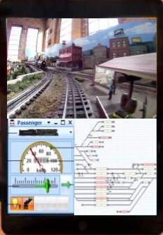
- Control a train from the perspective of the engineer. A tablet with the live video from the front of the engine, WIFI train control app and a map of the layout with control of the turnouts.
If 1 and 2 are accomplished a third goal would be to run a train as an engineer on my layout from anywhere in the world with fast internet. A test track to verify and debug the electronics to be used in a larger layout was built and electronics tested. The layout is an oval with two sidings shown in the figure.
There are 12 track blocks with labels starting with “B”. There are 12 3-aspect masts and 8 2-aspect masts with labels starting with “M”.
TMCC/Legacy and DCS engines can be controlled by traditional remotes, WIFI (cell phones and tablets) and by computers (Train Controller or JMRI). The layout and test track design for controlling engines is shown in the next figure.
The Dewenwils is a remote on/off switch for AC power to the track. An Antek An-6218-600VA 18V Toroidal transformer is used to convert the 120V AC to 18V AC. A single Antek transformer with 2 x 18V 8.3A outputs can supply 2 power inputs to a TIU. An Airpax 10A instant trip is used to help protect the TIU and engines. The DCS TIU receives commands from DCS remotes, DCS WIFI unit and the TMCC-to-DCS transmitter unit link. The DSC output is combined with the Legacy signal. A TVS is added for protection before the signals and power are distributed to the layout track. WIFI device apps communicate with the DCS WIFI unit, the LCS Legacy WiFI unit and the computer running Train Controller or JMRI. The Legacy base receives commands from the remote, the LCS WIFI and the computer through the LCS Serial. The Legacy output goes to the Legacy Booster and the TMCC-to-DCS unit. The WIFI tablet/cell phone can receive a live video feed from a FPV camera in the front of an engine.
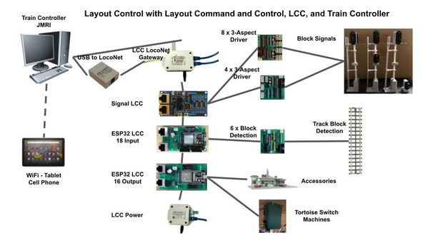
Random running of computer controlled trains requires block detection on most sections of track and control of the turnouts. The Train Controller app can randomly run trains on a layout with knowledge and control of the layout, trains location and ability to control the trains. An extensive signaling system can be implemented with the track block detection. The LCC network is used for block detection, signal logic, turnout and accessory control. The following figure shows the LCC network.
Train Controller communicates with the LCC network through a LCC/LocoNet Gateway because Train Controller does not yet support LCC (NMRA Standard). RR-CirKits Signal LCC, ESP32 LCC 18 Input and ESP32 16 Output are the nodes used in the LCC network. The ESP32 LCC nodes are my designs using modified versions of openmrnlite software. The LCC network and nodes are an example of edge computing where the Signal LCC node independently calculates the setting of the block signals and drives the LEDs. The control panels are all touch screen monitors or tablets. The video shows an engine going through several blocks and a 3-aspect and 3 over 2-aspect masts.
All the electronic functions were verified. The electronics and software shown are the basis to achieve these goals on a 30’ x 40’. I learned a lot from doing the test layout. I changed some of the design and learned how to make the assembly more efficient. Two important lessons are:
- Simplify as much as possible. The RR-CirKits Signal LCC can do complex signal logic to simulate prototype prototype rules and speed control. I used simple ABS rules.
- If you want items to stay glued together that have some stress use JB Weld epoxy. Various super glues and a UV cured glue did not hold consistently.
This post is an overview. Disclaimer - Some of the functions were tested in a subset of the electronics. Many ideas came from OGR posts. More information can be found in the following links.
LCC - http://www.rr-cirkits.com
The test track LCC network and costing - https://ogrforum.ogaugerr.com/...utomation-test-track
The TMCC to DCS transmitter - https://ogrforum.ogaugerr.com/...rom-train-controller
Description of the block signal drivers and the LCC forum. https://groups.io/g/layoutcomm...signal_cost_with_lcc
Carl


