I have come across a problem I have not seen before.  A buddy has had a PS1 E8 (don't know the stock #) converted to TMCC w/cruise and when it is advanced, (start it moving) it revs up to it's max, runs this way for 10 - 15 seconds, and then drops back to idle sounds while moving, all the time at the same speed.  There were no instructions sent back with the loco after the upgrade, so I am not sure what functions will reset it etc.. 


I did read this thread and can try it's reccomendations but thought I would also ask to see if anyone had any other ideas.  My buddy is bringing the loco over on Monday so I have some time to research and poke around looking for answers.


Thanks in advance for your help...

Original Post

Replies sorted oldest to newest

Years ago I bought an ICG gp-38 from weaver that had the same problem...sent it back and got it corrected.  I also had a tmcc lionel santa fe b unit with the same problem...I think I had this too corrected...but have not run this for years so I don't remember.  I think they both had the same kind of period sound units in them.

The Railsounds board requires a CAM signal to maintain the RPM level.  Probably the TMCC conversion process left the CAM out.  You can try to enter manual RPM mode by pressing the "6" key (RPM up),  The "3" key is the RPM down.  It may not hold the elevated RPM level however, only the ElectricRR upgrades had the ability to hold the manual RPM level without a CAM.  (We developed custom code for this feature.)


If the RPM won't hold in manual mode or the person does not want to use manual mode, you will need to add the CAM.  A reed switch can do the task.  Most upgrade boards have a CAM input.


Originally Posted by gunrunnerjohn:

Jon, don't thought some of the boards had a VCO that generated that signal.  The TAS EOB board I'm currently working on will vary the RPM with no cam input and any RS Audio board installed.  It also holds the higher speed as long as the motor is running at the same rate. 


The steam version has the external chuff input. 

John, true, EOB could generate a CAM signal.  Still, I believe that the missing CAM is the core issue for the failure. 


Since the EOB VCO was directly wired into the motherboard, I surmised this was not an EOB install because that wiring would be unlikely to fail.  Anyways, EOB or not, it needs a CAM to operate properly, or it will ramp down.  The RPM ramp down after motion is a dead giveaway it is missing the CAM signal.


Ok...  if this is the case, and by what you're saying it sounds very probable, can this be repaired by the original folks that did the install?  It was upgraded by Gary w/Weaver.  Is it possible that it was there and it has failed or disconnected?  I am not as familiar with these board sets as I am with MTH, so I'm not entirely sure what a "CAM", in this instance, is.

I finally got together with my buddy and tried the reset, no joy   So...  here are some pix of the innards of this engine.  If I understand the manual that Boxcar Bill linked to, this engine does not have the "VCO" connected.  My question is...  should it be or should these boards have the "CAM" that Jon wrote about?

IMG_1336

IMG_1337

IMG_1338

IMG_1339

Attachments

Images (4)
  • IMG_1336
  • IMG_1337
  • IMG_1338
  • IMG_1339

There's no downside to connecting the VCO to the motors, and it should solve the issue of the motor revs.


The curious thing is the RailSounds Commander in the pictures doesn't exactly match any of the ones I have installed or the manuals, including the one that Bill linked.  I wonder if that's just an older version of the RailSounds Commander?


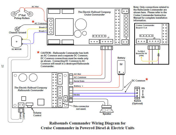
Here's the page that describes what I believe your configuration should be.  As you can see, there is no five pin connector, and the other connectors are not in the same positions.


Click on the picture to expand it.


rsc

Attachments

Images (1)
  • rsc

Cheryl


   The first pic in looks like a lionel sound mother board, 691PMB2A02.  In the first pic were is the red, black and gray wires connected , could you take a pic were the wires go to, I believe they are connected to a hall effect switch. If it they do go to the hall effect switch, the switch, wiring or the motherboard is bad. Try hooking the motherboard vco to the motors.


Bill

Last edited by Boxcar Bill
Originally Posted by Boxcar Bill:

Cheryl


   The first pic in looks like a lionel sound mother board, 691PMB2A02.  In the first pic were is the red, black and gray wires connected , could you take a pic. I believe they are connected to a hall effect switch. .


Bill

Bill, thanks again for your response and patience.  I'm at the shop now, will shoot the pix and post when I get home tonight. 

Cheryl, The VCO is a CAM pulse generator.  Try hooking up the VCO as suggested.  If you need a cable, email me with your address and I will ship one to you.


John, the pinout on the board you picture is the same as the ElectricRR upgrade board, with the following changes: The additional 3 pins by the speaker connectiosn are for the POT, as the POT is not installed.  The small 3 pin connection (lower left) is an additional input to the RS board for an "angle sensor"; used on the Vision rolling stock product; not active in the code on any other RS audio boards.


"Cheryl, The VCO is a CAM pulse generator.  Try hooking up the VCO as suggested.  If you need a cable, email me with your address and I will ship one to you."


Jon,


Thank you for the affirmation and the offer for the connector.  I do have some from various other engine projects that should work.  It appears to be the standard two pin connector found in most of the O Gauge train products.  Will post the results of my efforts later tonight.

Post

OGR Publishing, Inc., 1310 Eastside Centre Ct, Suite 6, Mountain Home, AR 72653
800-980-OGRR (6477)
www.ogaugerr.com

×
×
×
×
Link copied to your clipboard.
×
×