I am using an MTH Z4000 for power to my fixed channels on my MTH TIU. I will use both 20 volt outputs of the Z4000 to power my TIU track voltage. Since the Z4000 can deliver in excess of 10 amperes per output I have built a custom circuit breaker box which has a 10 ampere circuit breaker for each channel.


The circuit breaker box will be wired between the Z4000 and the TIU. The circuit breaker box also includes various lamps (LEDs) to indicate the condition of both channels.


Two green LEDS are wired across the inputs to the box. Another two red LEDs are wired across the outputs of the box.


In addition two large red LEDS are wired directly across the circuit breakers. These LEDs will be lighted in the event of a short. 


Note 1: Each of the LEDs also have a small diode in series to rectify the AC.


Note 2: I also have separate circuit breakers installed on the TIU outputs for additional protection.


All these circuit breakers are in addition to any circuit breakers and fuses already installed in the MTH equipment.

Original Post

Replies sorted oldest to newest

The trip limits of the Z 4000 seem to be between 7.5 and 10 amps and as mentioned very fast.  Please correct me if I'm wrong, the sum of both handles will shut the entire Z 4000 off, requiring reset of both the left and right handle.

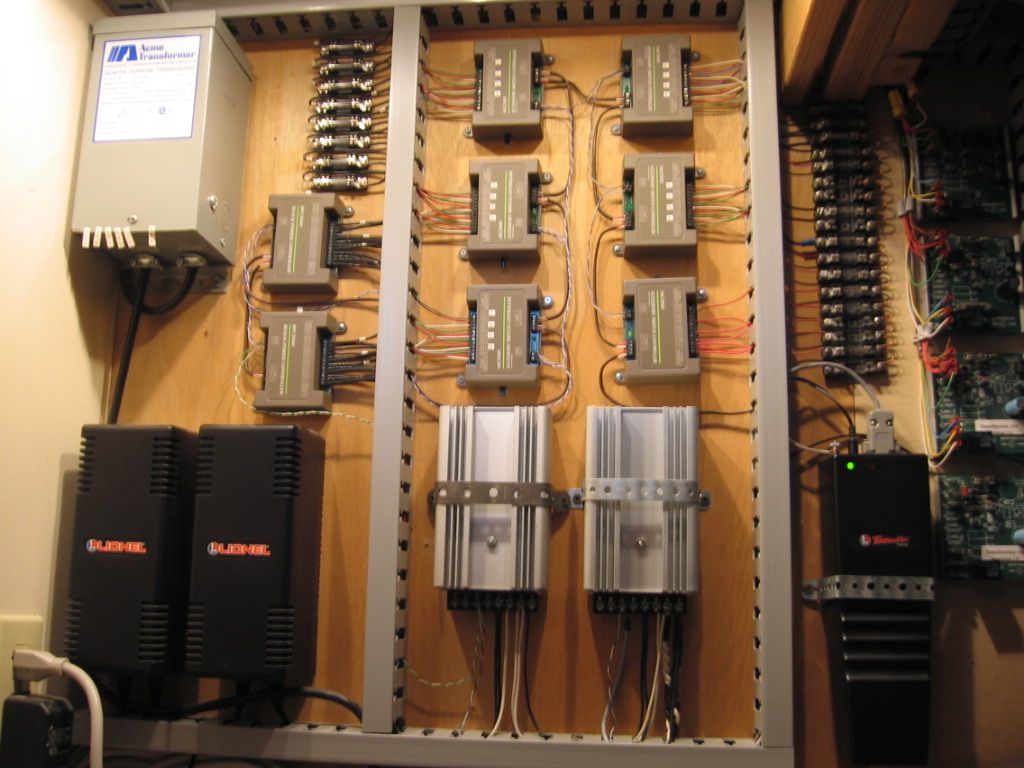
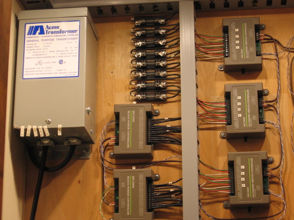
Parallel-ing bricks which may require the use of Track Power Controller (TPC) can apply easily 15 to 20 amps to a track circuit.  I distribute track power from Parallel PH135 via fuse blocks and fuses per track circuit at 7.5 amps.  Limits dead short derail arc and spark welding notice at 20 amps. IMO.

Track power fuses upper left.
  
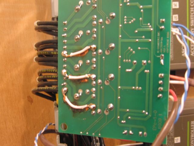
The 15 to 20 amps of current draw can also do damage to Block Power Controllers. (BPC's)  I had to replace burned traces on both the BPC's pictured.

Trace damage and repair of an IC Controls BPC.  Overload protection on the two PH 135's was 15 amps. 


Last edited by Mike CT

MIKE CT:


The Z4000 is rated at 180 watts per output.  With a voltage output from the Z4000 of 18 volts the Z4000 should be able to deliver 10 amperes continuously. The power box shown will disconnect power when the steady state current through the box is maintained at 10 amperes or above. In the event of a dead short the Z4000 would probably react before the external circuit breaker. At least the external breakers are there as a backup.


I also have separate individual circuit breakers for all my TIU outputs. These are 5 ampere circuit breakers.


Additionally I will also have individual 3 ampere circuit breakers for all individual  power feeds to the track. As a result a derailment (and short) at any one location on the track will NOT affect any other track feeds.


Emergency Shutdown control box

Not shown is my Emergency Shutdown control box.  This E-Stop box will contain high current relays.  I will have up to 4 "E-Stop" buttons available on my layout. If any one of these buttons is pressed all power from my Z4000 outputs will be disconnected and latched "off".  I will also have a reset button on the E-Stop control box to restore power.


MIKE CT:


Relay Board for controlling turnouts and track blocks


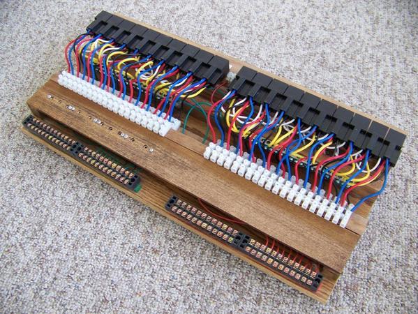
I have built a relay board to be used with my MTH AIU.  However this relay board is general purpose and could be used with the Lionel system or any other control system.


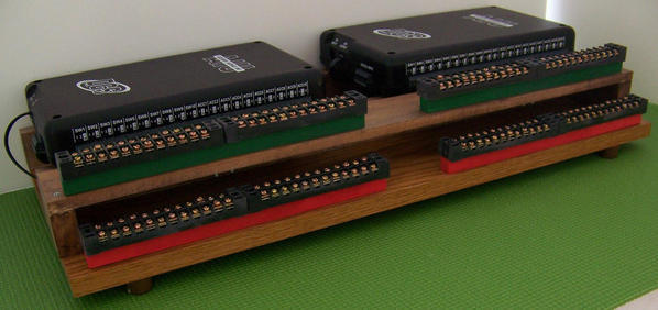
This relay board contains individual power relays.  See attachment.


The purpose of these separate relays is to limit the current through my MTH AIUs to about 1/2 ampere maximum. Therefore the current necessary to control a turnout or power a block is provided by the separate relay and NOT the AIU. The Relay Board is designed to connect to my AIU Patch Board. (See also attachment)


Note: Every relay "circuit" is protected by a combination of circuit breakers and fuses including all turnout solenoids. Each track "block circuit" is also individually protected in case of a short circuit or overload. This means that any individual fault anywhere on the layout will be detected and cleared without affecting any other circuit.


The second photo shows my AIU patch board.  It is a convenience termination board that interfaces with the relay board. Note: Two AIUs are shown. Each AIU can control up to 20 circuits.


relay board 2

AIU patchboard 4

Attachments

Images (2)
  • relay board 2
  • AIU patchboard 4
Post

OGR Publishing, Inc., 1310 Eastside Centre Ct, Suite 6, Mountain Home, AR 72653
800-980-OGRR (6477)
www.ogaugerr.com

×
×
×
×
Link copied to your clipboard.
×
×