Here is a fun project that I need help on....pictures would be great!! I'm about to install the Williams Reverse Board and True Blast Horn to one of my Lionel 2333 F3's. I'm looking for info on where & how to mount the reverse board on the A Unit. Look's like best area is over battery holder; Williams give you a metal 'L' bracket....attaching to the old e-unit screw mount looks like it my come loose so I'm thinking of drilling a small hole through the battery bottom that looks like a fuel tank from outside.

Also have Williams True Blast II Horn that will go in a B unit that I bpurchased on ebay that has a speaker grill where battery door would be.

Mark Brown
Original Post

Replies sorted oldest to newest

I decided to put this to the test. I have a 2333 that has no magnatraction and a 2344 which has magnatraction. Using a post war LW transformer, the 2333 A-A cruises at 2.5 amps and flashes to 6 amps on start up. The 2344 A-A cruises at 5 amps and flashes to 7 amps on start up. This is why Dallee says their standard 4 amp reverse board will not work with Post war engines I guess. I would follow what Dale and Chuck tell you.
Rob
Last edited by oldrob
Dale, Is only stating a method to run an AC motor on DC, not whether the board can handle it.

If the board is rated at 4 amps, sounds like they are using the similiar TIP transitors as on the Lionel 103 E-unit. Notorious for burning up when DC cans drew too much current.

Dale, I converted some AC Alco using the Rectifier method and a Lionel 103 E-unit meant for DC motors. It works, but it is not more efficient, and you do loose top end speed from the voltage drop.

Worth doing to replace a 2 position e-unit and more children friendly. G
Hi guys....thnaks for all the posts! I'm attaching a picture of the Williams Reverse Board #00247. It is a 6 amp unit. I've also posted the instructions with a schmatic picture at the bottme that may help one of you nail this challange.

My project here is that I bought and old Texas Special frame & motor to fit my postwar-reissue Canadiam Pacific shell(For A Unit and B Unit). I have cleaned up the frames and whells and repainted them falt black to match the shells. The Williams reverse board will replace the e-unit...hopefully, while I still retain the 'growl' of the motor. I have installed a Williams True Blast sound board & speaker in the 'B' unit...facing it up towards the roof screens for sound. It is a cool project and if I nail this reverse board or end going Dalle, then I will be happy!

Mark B.


quote:
Originally posted by oldrob:
I decided to put this to the test. I have a 2333 that has no magnatraction and a 2344 which has magnatraction. Using a post war LW transformer, the 2333 A-A cruises at 2.5 amps and flashes to 6 amps on start up. The 2344 A-A cruises at 5 amps and flashes to 7 amps on start up. This is why Dallee says their standard 4 amp reverse board will not work with Post war engines I guess. I would follow what Dale and Chuck tell you.
Rob


HI Rob....see my most recent post of a picture & schmatics of this 6 Amp Williams Reverse Board. Any of this help towards making this a go? Can I add something to the board to make it better/more compatible? Thanks!

Mark B.
quote:
Originally posted by broadythecableguy:
quote:
Originally posted by Dale Manquen:
You could make it work if you added a full-wave bridge to drive just the field coils. That would cost you about 1.5V of drop, but you would probably get that back with the extra efficiency of DC.

Aren't the 2333/2334 the non-Magnetraction versions?


the 2333/2333 are non-Magnetraction versions there wasn't a 2334

Scott


HI Scott, that sounds good and doable. Where would I place the FULL-WAVE BRIDGE? Between the Reverse Unit and the RED wire or the BLACK ground?

Mark B.

quote:
Originally posted by Mark B:
quote:
Originally posted by broadythecableguy:
quote:
Originally posted by Dale Manquen:
You could make it work if you added a full-wave bridge to drive just the field coils. That would cost you about 1.5V of drop, but you would probably get that back with the extra efficiency of DC.

Aren't the 2333/2334 the non-Magnetraction versions?


the 2333/2333 are non-Magnetraction versions there wasn't a 2334

Scott


HI Scott, that sounds good and doable. Where would I place the FULL-WAVE BRIDGE? Between the Reverse Unit and the RED wire or the BLACK ground? Here is a picture of a Graham Full Wage Bridge.

Mark B.

Here is a method to operate the AC motor with a DC board and rectifier.


Hot + DC wire from Reverse unit to one AC terminal of the bridge rectifier
The armature across the + and – of a Full Bridge Rectifier
The other AC terminal of the bridge to one of the field coil ends
The common point of the field coil to DC ground on the PC board.

What this does is always ensure DC current to the armature flows one direction because of the FBR, but the current through the field reverses with the DC Reverse unit changes. This reverses the direction of the motor.

If you have a volt meter/Current meter on you layout it would be nice to read the values in AC, then after the conversion. I think top end speed will drop off. G
In an earlier post I forgot that changing from a mechanical E-unit to a DC sequencer such as the Williams board actually adds 2 diode bridges into the picture - one on the board and one for the AC motor. There is maybe capacitor somewhere to get a bit of peak voltage off the AC waveform, but at full load you are looking at about 1 volt per diode for a total drop of 4 volts.

On a dual-motor engine you only need one bridge across the two armatures connected in parallel.

GGG's method is a bit easier than putting the bridge around the field winding since you would need to lift the ground leads of the fields of both motors to insert the bridge. The end result is the same.
quote:
Originally posted by Dale Manquen:
In an earlier post I forgot that changing from a mechanical E-unit to a DC sequencer such as the Williams board actually adds 2 diode bridges into the picture - one on the board and one for the AC motor. There is maybe capacitor somewhere to get a bit of peak voltage off the AC waveform, but at full load you are looking at about 1 volt per diode for a total drop of 4 volts.

On a dual-motor engine you only need one bridge across the two armatures connected in parallel.

GGG's method is a bit easier than putting the bridge around the field winding since you would need to lift the ground leads of the fields of both motors to insert the bridge. The end result is the same.


Dale, the 2333 that I have has 1 motor. Not sure if that changes things.

Mark B.
quote:
HI Rob....see my most recent post of a picture & schmatics of this 6 Amp Williams Reverse Board. Any of this help towards making this a go? Can I add something to the board to make it better/more compatible? Thanks!

Mark B.


If it were mine, and I am saying IF it were me, I would chuck the Williams board idea and do one of two things. Buy a Dallee board that is designed for AC motor operation and comes with instructions, or just wire it straight where you have forward only. Another idea might be to find a reverse board out of a late model Lionel AC pullmore motored engine and try that. These are my suggestions.
Rob
quote:
Originally posted by Dale Manquen:
Does your unit have a horizontal-shaft motor or a vertical shaft motor? A 2333 should have 2 horizontal-shaft motors. Where is your motor - front or rear? This is an F3, right? Not an Alco 2033?


Dale, the motor is in the back of the F3, which is a 2333-20. I purchased this last year....it was a Texas Special w/out the shell. For whatever reason, my Canadian Pacific shell would only fit this frame style and it had the clip mounts on the back.

Mark B.

Here is a shot of my motor that I just grabbed off of Ebay:

quote:
Originally posted by oldrob:
quote:
HI Rob....see my most recent post of a picture & schmatics of this 6 Amp Williams Reverse Board. Any of this help towards making this a go? Can I add something to the board to make it better/more compatible? Thanks!

Mark B.


If it were mine, and I am saying IF it were me, I would chuck the Williams board idea and do one of two things. Buy a Dallee board that is designed for AC motor operation and comes with instructions, or just wire it straight where you have forward only. Another idea might be to find a reverse board out of a late model Lionel AC pullmore motored engine and try that. These are my suggestions.
Rob


Hi Rob, that is a good idea and may be the best ending to all of this. I can either sell the Williams board on Ebay, or keep it for a Williams 'juner' project.

Mark
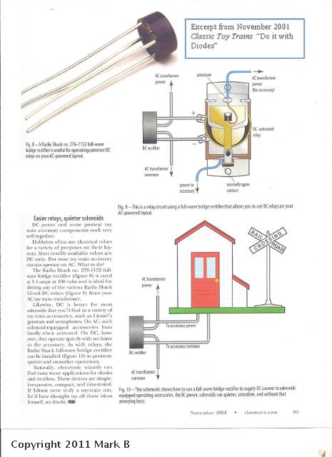
Hi all...per Rod's message it looks like this can be done as he had it done to a similar Lionel F-3 several years ago. I Googled Radio Schack 6AMP Bridge Rectifier and came up with the below photo using the RS BRidge Rectifier for a Lionel DC Relay(The paragraph on this phto states that this particular rectifier RS#276-1152 is rated at 1.4 AMPS.

Using this info...are we close to anyone figuring out I can do a similar hookup with the William's Reverse Board? I would think the conscep t is very similar if not alike and all I would need is , I think, a 6 or 8 AMP Bridge Rectifier and the map-schmatic to wire it up to the Williams Reverse Board.

Thanks! Mark B.

quote:
Originally posted by GGG:
Mark, Did you miss my post? Yes the 6 amp bridge will work. I gave a word description of how to wire it. G


G....thanks for the reminder. Your note is perfect for the 6 AMP Bridge Rectifier. I will pick one up at Radio Shack and wire things up. I just got a volt/amp meter and will get the numbers for you before & after the conversion. Once it's all together I'll post some pictures for you and other OGR members so that they will have a one stop solution for this project.

Mark B.
Mark, Just to clarify, you state you have a TS F3 frame. That is a 2245 number. The first year of this TS they used the single horizontal motor like the 2333. Since this is not magnetraction I think it will work fine.

I looked at my notes. I converted a 211 TS Alco with a 2 position reverse unit, Pul-mor and magnetraction. I used the Lionel 103E unit (4 amps) and a 4 amp FWBR. It runs fine and has not had problem pulling the lighted dummy A and a set of MPC modern Lionel cars.

Your engine will be a little heavier and a stronger motor. You also have a single wound field.

The e-units for these engines reversed the polarity thru the motor armature while keeping the same direction thru the field windings.

Here is my revised connections:

Power the E-unit normally with AC track power

Hot + DC from E-unit to either AC connector on the Bridge. The other AC terminal on bridge goes to one of the motor brushes and the other motor brush goes to the - DC from the e-unit.

Disconnect both field winding leads from any terminals (brushes) on the motor and/or frame (via a screw). One field lead goes to the +DC of the FWBR and the other lead goes to the -DC of the FWBR.

If the unit starts in reverse, just swap the field leads on the FWBR.

When the polarity of the DC output flips on the E-unit the current will flow in the opposite direction thru the motor armature, but the bridge rectifier keeps the current flow thru the field winding the same. Therefor the motor will switch directions. This mimicks the same process of the mechanical or electronic AC reverse units. Good Luck. G
quote:
Originally posted by GGG:
Mark, Just to clarify, you state you have a TS F3 frame. That is a 2245 number. The first year of this TS they used the single horizontal motor like the 2333. Since this is not magnetraction I think it will work fine.

I looked at my notes. I converted a 211 TS Alco with a 2 position reverse unit, Pul-mor and magnetraction. I used the Lionel 103E unit (4 amps) and a 4 amp FWBR. It runs fine and has not had problem pulling the lighted dummy A and a set of MPC modern Lionel cars.

Your engine will be a little heavier and a stronger motor. You also have a single wound field.

The e-units for these engines reversed the polarity thru the motor armature while keeping the same direction thru the field windings.

Here is my revised connections:

Power the E-unit normally with AC track power

Hot + DC from E-unit to either AC connector on the Bridge. The other AC terminal on bridge goes to one of the motor brushes and the other motor brush goes to the - DC from the e-unit.

Disconnect both field winding leads from any terminals (brushes) on the motor and/or frame (via a screw). One field lead goes to the +DC of the FWBR and the other lead goes to the -DC of the FWBR.

If the unit starts in reverse, just swap the field leads on the FWBR.

When the polarity of the DC output flips on the E-unit the current will flow in the opposite direction thru the motor armature, but the bridge rectifier keeps the current flow thru the field winding the same. Therefor the motor will switch directions. This mimicks the same process of the mechanical or electronic AC reverse units. Good Luck. G


Thanks G for the detail. Here is some final background before ai take off on this>>>>THanks for your patience and knowledge!!! The frame I have is stamped 2333-30. It has a single motor which is same type that you find in the dual motor 2343's. Per Greenberg's that does not seem correct, but who knows what happend on that particular procuction run or over the past 5 decades! I'm still learning all things postwar as I go along. How do I determine if it is magnetraction? A small drill bit is pulled by the wheels, so it appears to have magnetration....correct? Luckily, I took a picture of the unit prior t o taking it apart to paint flat balck for my Canadian Pacific shell.

quote:
Originally posted by Dale Manquen:
The 2333-30 is the part number of the casting, not the specific locomotive. That same casting was used on all the horizontal motor F3 versions.


Thanks Dale. I checked out your attic layout. Very cool use of space. I have a similar sized attic and have thought of doing the same.

mark B.
I didn't check GB, but the PW repair manual talks to the early TS having the horizontal motor, before they switched to vertical.

That is a nice original frame. You painted it what!!! Red Face Smile

You will remove the horn, battery bracket/relay, and e-unit to make room I assume? Ensure you insulate under the Williams board before mounting to frame. Double side thick tape works. G
quote:
Originally posted by GGG:
I didn't check GB, but the PW repair manual talks to the early TS having the horizontal motor, before they switched to vertical.

That is a nice original frame. You painted it what!!! Red Face Smile

You will remove the horn, battery bracket/relay, and e-unit to make room I assume? Ensure you insulate under the Williams board before mounting to frame. Double side thick tape works. G


Thanks G. Yes I did paint it in a moment of madness! Seriously though, I bought 2 beautiful postwar/new Candian Pacific shells A & b for this project and black was the way to go...flat black that is.

I've removed the hron and relay and installed a Williams True Blast horn in an an old B unit that I picked up that had roller poick ups and a speaker grill on the bottom. Interestingly, although it's Lionel, it was made in Mexico. It was a bit beat up but look's A-1 know with black paint. I will add the picture here shortly.

The Williams Reverse Unit will fit in the battery area of the A unit with some double stick tape.

Mark B.


Post

OGR Publishing, Inc., 1310 Eastside Centre Ct, Suite 6, Mountain Home, AR 72653
800-980-OGRR (6477)
www.ogaugerr.com

×
×
×
×
Link copied to your clipboard.
×
×