Is this feasible?


 I run three stop-and-go trolleys on a large loop.  Two are stopped at stations while the third runs over the insulated startup track section(s) and then it stops etc.  Everything works great but it would look much better if a trolley’s interior lights remained on when it stops.  


Idea:   1 – Remove interior bulb(s).   2 – Add a capacitor and LED lighting. 3 – Charge the capacitor with track power.  As the trolleys run, the capacitors come alive and lights remain on until the capacitor looses charge from power-off.  


 If this is doable, I would appreciate recommendations and/or a parts list. 


Thanks for reading,

 Paul


Long time with trains –First time on Forum  

Original Post

Replies sorted oldest to newest


 That's welcome news. Thanks.

1.  minute or two.

2. Cost shouldn't be an issue.
3. Have done of fine soldering, but not with diodes.
4. Trolley's are current MTH models but no Pics at moment.**

* A trolley travels an 80' track back and forth (160') between 2 reversing loops where others wait.
** This is a club layout. I'm going out of town and won't have access for a while.
 

Regards

Originally Posted by 1942guy:


 That's welcome news. Thanks.

1.  minute or two.

2. Cost shouldn't be an issue.
3. Have done of fine soldering, but not with diodes.
4. Trolley's are current MTH models but no Pics at moment.**

* A trolley travels an 80' track back and forth (160') between 2 reversing loops where others wait.
** This is a club layout. I'm going out of town and won't have access for a while.
 

Regards

Welcome,

Looks like you've almost got this sorted on your own "42"


#1 being answered as close as possible will get a very exact part out of Stan to get you what you want.  I don't think two minutes is going to be hard. No longer than that?

 FYI -You have attracted some of the best help you can get with John and Stan.


 Soldering an electronic components leg off a board, is very much like soldering wire, but pre-tinning it can normally be skipped. Pliers as a heat sink at the leg base if you are really having to heat the job hard. Like anything, sometimes it will go better than others. But its normally easy. On boards you just fit the leg in the hole. Heat the tip and trace as you fill it. 

 Even with too much heat, you wont burn the components nearly as often as you'd first cook traces till they peel off a board.

 Plumbing solder, will only make you curse. Use electrical solder.

Flux is for "dirty" things, and old wire. It really helps too. Its a cleaner.(remove excess) 


Good luck!


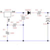
Install constant voltage lighting using LEDs. Here are 2 different ways


LINK1


LINK2


This will give constant intensity lighting from about 5 volts up. Using multiple  1 farad super capacitors in link 2, added to the regulated 5 volt end,the lights will stay on when power is removed for 30 seconds or more. I use five,  1 farad button type,they mount easily to the fish paper linked. I do this on passenger cars and they stay lighted fairly well for up to 2 minutes,gradually fading. They still glow very faintly after an hour or more.


Or


 insert a diode string in series to the motor(s). Enough diodes so the trolley motor stalls at 5 volts input. Instead of cutting power completely to the trolley during a stop,leave on 5 volts instead. This can be accomplished with a relay spdt where the 5 volts is inputed into the NO contacts.


The diode string is shown here.

If the trolley only runs one direction you only need a single string.  for a trolley 3 amp or even 1 amp diodes are OK sometimes depending on the trolley


LINK3


Dale H

Last edited by Dale H
Originally Posted by 1942guy:
1.  minute or two.
2. Cost shouldn't be an issue.
3. Have done of fine soldering, but not with diodes.
4. Trolley's are current MTH models but no Pics at moment.**

* A trolley travels an 80' track back and forth (160') between 2 reversing loops where others wait.

As others point out, the 2 minute specification makes this very interesting. 


A few more follow-up questions.


5. So a trolley stops/waits on a reversing loop with no track power for up to 2 minutes. When a trolley runs on powered track, a) what is the minimum "guaranteed" track voltage and b) for how long will that trolley be on powered track before stopping?  This line of questioning goes to the ratio of charging vs. discharging time which applies if using some kind of energy storage device (capacitor, battery, momentum flywheel, whatever).


6. What are the MTH stock numbers of these trolleys? There's a rechargeable battery in the MTH Protosound 2 variants if that's what you mean by "current" models.  That said, is OK to tap into this battery as a source of backup power?  I'm not asking how-to, but as a logistical matter - for example, you may have taken out the PS2 electronics and put in a barebones motor controller. 


7. If using stock PS2 electronics, are the trolleys operating conventional-mode (track voltage controls speed) "locked" in forward direction?


8. Read Dale H's method of lowering the voltage to just the motor while keeping a higher voltage available to the PS electronics to keep the lights running.  So rather than turning off track voltage to a stop block/section, you would reduce it.  You have to think about it for a while and read his linked info.  Along the same lines, if you are using stock MTH electronics in conventional-mode with factory-default speed-control turned "on", note there is a small-zone of track voltage where the electronics is ON (lights, sounds, etc.) but the trolley is stopped.  It's around 6-8 V on the track.  Did you already try this?  For example, rather than turning OFF power to the station stop blocks/sections you would apply, say, 7V.  The trolley would stop moving but the electronics (lights/sounds) would be active.  Variants of this idea may include switching over to DC track power as it might be easier to generate the correct "stop" voltage with DC than AC as current MTH electronics can operate on either.


Last edited by stan2004

One thing about using a superCAP or several of them to add capacity.  You can charge them far faster than they discharge, unlike traditional rechargeable batteries. 


I just connected two 2.5F 5.5 volt superCAPs to a 39 ohm resistor and three parallel LED's.  Feeding that I have a diode (to block reverse flow to the power source).  I feed the network with 5.5 volts.  The caps easily charged up from a 1A current limited supply in about 25 seconds, and the LED's were burning brightly.  I killed the input power and the three LED's burned for over three minutes at a nice brightness.  At the two minute mark, I still had over 4 volts across the superCAP bank and the LED's were burning brightly.


The caps are $4/ea, a regulated power supply is $3-4, and you just have to wire up the LED's.


If you want more LED's, you could add another cap or two.


Originally Posted by BillP:

Suppose you wanted to drive 6 LEDs, headlight,  three overhead interior lights, two red tail lights.  


What at would be a good circuit?  What would be the function for computing light time from the capacitance?

A back-of-envelope engineered-design would convert your lighting power requirement into energy.  Energy (in Joules) = Power (in Watts) x Time (in seconds).


Let's say each LEDs is 3 Volts drawing 0.02 Amps (20 milliamps).  Power (Watts) = Voltage (in Volts) x Current (in Amps).  So each LED requires 0.06 Watts.  Now say you want to power your 6 LEDs for 10 seconds.  The energy needed is 6 x 0.06 Watts x 10 seconds = 3.6 Joules. 


The theoretical energy stored in a capacitor is 1/2 x Capacitance (in Farads) x Voltage x Voltage (in Volts).  So a 1 Farad capacitor (a typical supercap value that runs about $5) charged up to 5 Volts stored 1/2 x 1 Farad x 5 Volts x 5 Volts = 12.5 Joules.


So that supercap, fully-charged, has enough energy to power the LEDs for 10 seconds.


Then you start dealing with practical issues such as you can't really squeeze all the energy out of the supercap.  For example, as the supercap discharges, its voltage drops.  At some point the voltage drops below 3V (or whatever the LEDs need to operate) and the stored energy is for naught.  Then you design a circuit to boost that low voltage up above 3V to squeeze out the last ounce of energy.  Or you play with the variables (add another supercap to have more energy to begin with).  Or, and so on.


There are other design considerations - for example, on the charging side there are practical issues of how fast you can charge a supercap.


Originally Posted by gunrunnerjohn:

With six LEDs, I'll bet three of the 2.5F caps will get it done for two minutes.   Even if they get a bit dimmer, they're still light, and the slow decay would probably not be that noticeable.  It's simple and fairly cheap to build.


I stand ready to throw darts at any circuit you propose!


In your previous example of the supercap dropping to 4V, I calculated an approximate drop of 30-40% in LED brightness.  This is occurring over many tens of seconds you so probably don't notice it.  And it does make for a simple circuit.  But if the OP wants constant-brightness, then additional regulation is required.


However, I'm curious how you make a simple and cheap rapid charging circuit.  A 1 Amp constant-current charger that cuts off when the supercap(s) reaches 5V is "easy" if you have a bench power-supply.  But a hand-built circuit? 


Also, when the supercap is charging for tens of seconds, I'd think you want full-brightness on the LEDs.  Or maybe not?  If so you need a bypass circuit - could be as simple as diode OR'ing - to power the LEDs to full-brightness whenever track power is available.


The 1A supply is actually easier than it sounds.  You just need the 5.5 V adjustable supply, the diode, and a low value resistor.  I'd consider a 5-6 ohm to start.  Dropping 5V across the 6 ohm during the initial charging state is possible and it ends up less than an amp surge current.  It actually charges the caps pretty quickly, and remember that we're not ever totally discharging them, we just want to run 2 minutes and then we'll have the "charger" working again.  When we're running under power, the few ohms of the series resistor is insignificant in lighting the LED's. 


The only time you'd ever notice the caps charging is on initial power on, after that they should already be charged to a reasonable level.


It's the KISS method.  No switching, just a 1A adjustable supply, a diode, and a couple of selected resistors.


Fire those darts, be make sure you hit the target.


Now, if he's anal about truly constant intensity, you'd probably have to add some complexity.  Truthfully, I think this would do the trick and nobody that didn't know the secret would realize that the intensity changes some during the power off cycle.


Originally Posted by stan2004:
Let's say each LEDs is 3 Volts drawing 0.02 Amps (20 milliamps).  Power (Watts) = Voltage (in Volts) x Current (in Amps).  So each LED requires 0.06 Watts.  Now say you want to power your 6 LEDs for 10 seconds.  The energy needed is 6 x 0.06 Watts x 10 seconds = 3.6 Joules. 


The theoretical energy stored in a capacitor is 1/2 x Capacitance (in Farads) x Voltage x Voltage (in Volts).  So a 1 Farad capacitor (a typical supercap value that runs about $5) charged up to 5 Volts stored 1/2 x 1 Farad x 5 Volts x 5 Volts = 12.5 Joules.


So that supercap, fully-charged, has enough energy to power the LEDs for 10 seconds.


Then you start dealing with practical issues such as you can't really squeeze all the energy out of the supercap.  For example, as the supercap discharges, its voltage drops.  At some point the voltage drops below 3V (or whatever the LEDs need to operate) and the stored energy is for naught.  Then you design a circuit to boost that low voltage up above 3V to squeeze out the last ounce of energy.  Or you play with the variables (add another supercap to have more energy to begin with).  Or, and so on.


There are other design considerations - for example, on the charging side there are practical issues of how fast you can charge a supercap.


I question the calculations here.


The energy needed to light the LED's for 10 seconds is 3.6 Joules.

The fully charged capacitor has 12.5 Joules of stored energy.


Why can it only light the LED's for 10 seconds?  I know you can't squeeze all the energy out, but surely you can do better than less than 30%.


What am I missing?

Originally Posted by gunrunnerjohn:

The 1A supply is actually easier than it sounds.  You just need the 5.5 V adjustable supply, the diode, and a low value resistor.  I'd consider a 5-6 ohm to start.  Dropping 5V across the 6 ohm during the initial charging state is possible and it ends up less than an amp surge current.  It actually charges the caps pretty quickly, and remember that we're not ever totally discharging them, we just want to run 2 minutes and then we'll have the "charger" working again.  When we're running under power, the few ohms of the series resistor is insignificant in lighting the LED's. 


The only time you'd ever notice the caps charging is on initial power on, after that they should already be charged to a reasonable level.


It's the KISS method.  No switching, just a 1A adjustable supply, a diode, and a couple of selected resistors.


Fire those darts, be make sure you hit the target.


Now, if he's anal about truly constant intensity, you'd probably have to add some complexity.  Truthfully, I think this would do the trick and nobody that didn't know the secret would realize that the intensity changes some during the power off cycle.


KISS is fine, but a fixed-value resistor is a very slooow way to charge a supercap.  So when you say 5 ohm resistor, that is a peak current of 1 Amp if from a 5V source and only occurs if the supercap starts totally discharged.  When the supercap reaches 3V, the charging current drops to 0.4 Amps.  When the supercap reaches 4V, the charging current drops to 0.2 amps.  And the current keeps dropping.  Basically you have the so-called RC time-constant which is the product of R and C, or in this case 5 ohms times 2.5 Farads which is 12.5 seconds.  Starting from a discharged cap, it takes about 4 time constants or 50 seconds to charge up the cap to 99%.  OTOH, if you had a constant-current charger which is what you'd find in engineered rapid-charger circuits (more complex), a 1 Amp charger would fully charge the cap 4 times faster.


So with your basic KISS circuit, the LEDs would slooowly dim over a minute or whatever when no power is available, and then slooowly get brighter over a minute or whatever when power is restored.  It's not a question of right or wrong but just need to be clear on the alternatives.

Originally Posted by gunrunnerjohn:
Originally Posted by stan2004:
So that supercap, fully-charged, has enough energy to power the LEDs for 10 seconds.

I question the calculations here.


The energy needed to light the LED's for 10 seconds is 3.6 Joules.

The fully charged capacitor has 12.5 Joules of stored energy.


Why can it only light the LED's for 10 seconds?  I know you can't squeeze all the energy out, but surely you can do better than less than 30%.


What am I missing?

You're missing nothing.  Just semantics.  If you're going to buy me a beer that costs $5 and you have a $20 bill, then your $20 bill will pay for the beer.


For hobby purposes, when all's said and done, when you do the back-of-envelope calculations on how many Farads you need, or how many seconds you'll run for, etc. then double/halve the calculation to be conservative.  In other words, you might be able to recover 50% of the theoretical stored energy. If you're engineering the circuit using power management devices such as step-up or step-down switchmode devices,  an aggressive design (which comes at a cost) might shoot for recovering 80-90% of the stored energy.

You fellas are blowing me away. Even experimenting?  I'm really amazed at everyone's abilities and appreciate all the interest and time.


Feel obligated to get into the club tomorrow, run the trolleys and get some actual times. Also take a few pics. All Trolleys are similar to MTH #30-2545 (Not PS 2.0).


I confess, some of the technical information is overwhelming but I understand the concepts.


Thanks again.

Stan, the 50 seconds doesn't appear to be an issue with the lighting, so I don't see the problem.  In actual bench tests with three LEDs and two 2.5F supercaps it looked great.  I had two minutes off and one minute on, and the dimming of the LED's was noticeable but not that significant.  The fact that it happens slowly is a bonus IMO as it lessens the impact of any intensity change.


It's up to 1942guy to say if this is sufficient.   It's simple and cheap...


GRJ, OK by me. Let's call your design the baseline.  What is the parts list?  And did you happen to note the voltage of the LED and supercap at the start and end?  Presumably you just have a resistor between the supercap and LEDs so the voltage measurements will also give us start and end current.


Separately, I was thinking about how geeky using Joules is.  I figure kW-hr as a measure of energy is more familiar since that's how you pay your electric bill.  OK, so here's the math. 1 kW-hr is 1000 Watts for 3600 seconds.  That's 3.6 million Joules! 


So here we're talking about, say, 50 Joules of energy going in and out of the supercap for each lighting cycle.  That's about 0.00001 kW-Hrs.  With electricity costing about 10 cents per kW-Hr from a utility, we're talking 0.0001 cents!


Boy, if you can get electricity for 10 cents KW/HR, you're doing a lot better then I am!  I live in PECO country, it's around 15 cents.


I didn't actually take all the measurements and log them, but I was taking a few.  At the 2 minute mark the voltage was 3.6V across the caps.  When "fully" charged after a minute, the voltage was 4.95V across the caps.  That was from a full discharge, I didn't do any additional measurements.  The lights remained on slowly dimming for over five minutes.  The resistor I was using was a 39 ohm, but I think I'd cut that to the 33 ohm for the "production" version.


If you have three LEDs, the parts list is one 5 ohm 1W resistor, one 1N4003 diode, two 2.5F 5.5V supercaps, and a 33 ohm 1/4W resistor.  You'll need the adjustable 5.5VDC 1A power supply to provide the power.  Since the peak power is only for a short time, you could do this with an LM317T, diode, cap, and a 22uh choke for DCS compatibility.  You can also do it with the canned power supplies we routinely point out on eBay.


Like I say, this isn't a "perfect" solution, but IMO it looks pretty good, it's dirt simple, and pretty inexpensive as well.  For more LEDs, you can add a couple more super-caps.  Obviously, that will extend the "full" charging time, if you have a reasonable charging time between the station stops, I think it should work out.


My advice would be to do a test run with one set of components and see if the results are satisfactory.


Times:


I made it to the layout this afternoon.   It was a good thing.  My guesses were definitely off.  I timed the trolleys using a Z4000 at 12 volts and each stopped for 34 seconds and ran for 23 seconds in turn repeatedly.


Not being schooled in the technical aspect of this project, I’m indeed fortunate to have this forum and those who are good at it.  At the risk of stating the obvious or sounding Blonde, all I can deuce from these numbers is that whatever type, size or quantity of capacitors, they must charge faster than they fade.  Do I hear a Duh?


Fortunately, one of my best railroad buddies has experience with these type of parts. There are other men in the club that understand them too.


I have a good feeling about all this. Thank you!  


Photos of open trolley and layout stops:

There appears to be plenty room in these trolleys.


Will be gone Friday to Thursday.  

View 1


Station 1

Station 2

Attachments

Images (4)
  • View 1
  • View 2
  • Station 1
  • Station 2

John and Stan - as usual, your electrical/electronics musings are very educational - if not entertaining - and way beyond expectations in terms of helping out a fellow modeler.  I do have a question - originally posed 'a while back' by Bobby Ogage - which is why not use a battery and a charging circuit instead of a capacitor-based design.  Doesn't a battery approach provide greater flexibility in terms of how the system is operated (especially if the run time is shorter than the stop time)?

Not really. A cap, or super caps are ideally suited for this application time wise.

A trip to Radio Shack & I can get 4 grains of wheat to light for 30 seconds with normal caps in the supply, and it all could still be smaller than a aa battery.

Size and longevity? They win. Charge cycle ability, they win.

It will also be an automatic on and off, no power switch to forget about, or charge to keep up. It will outlast most batteries.

 Now these guys have a shorter time to work with, it especially suits the need.

Any nitpicking is an attempt at "the perfect circuit", time, ease, expense, etc. There is more than one path here.

Once done, he may never need to touch it again, ever. 

Last edited by Adriatic

The battery charges much slower than it would discharge, so IMO would not be an ideal candidate for this job.  The superCAP seems a perfect fit, you can fast charge it in a short time, and it'll keep the lights on for plenty of time.  Seeing the size of the trolleys, I'd say that the three LED's inside would be plenty, I'd use some wide-angle ones to spread the light. 


As far as room, the superCAP and associated components are pretty small, so that won't be an issue in almost any environment.  Here is the 2.5F 5V superCAP I spoke of.  Diodes and resistors can be had at the same site. 

Originally Posted by 1942guy:

Will be gone Friday to Thursday.  


Let me sneak a few more questions in before you go.  You have answered all my questions to date (and thank you for that).  So continuing on to the proverbial "20 questions"


9. I see these trolleys have directional lighting - appear to be LEDs.  You previously mentioned only the interior lights need to stay on at the stop.  So it's OK to turn off directional headlights while stopped?


10. Roughly how long is the trolley car?  I'm thinking you might be able to use LED lighting strips often discussed for passenger cars.  They come in increments of 2 inches.  They may need to be modified, but I think might result in a net-positive wrt easy-of-assembly.


11. How do you stop trolleys at the stations?  Are there relays that cut power to each station block?  I still have not given up on a variant of Dale H's notion of keeping some variant of track power applied at a station stop.

Originally Posted by richs09:

...Doesn't a battery approach provide greater flexibility in terms of how the system is operated (especially if the run time is shorter than the stop time)?

Adriatic and GRJ pretty much say it all but here's a couple additional comments:


1. A 9V style NiMH might be rated, say, 8.4V 120 mA-Hr.  So let's do the back-of-envelope math.  That's 8.4V x 0.12 Amps x 3600 sec = 3629 Joules.  So clearly a charged battery can store a whopping amount of energy relative to a supercap and relative to the task at hand (maybe 50 Joules or so).  So it's not that it won't work!


2.While maybe apples-oranges comparison, it's interestingthat MTH initially started with rechargeable batteries in their PS2 electronics, which an aftermarket company then made a supercap (BCR) alternative for those batteries, and then now MTH uses supercaps in their PS3 electronics.  Yes, a lot has been going in terms of improving the supercap technology and cost during that period but again just an observation.


Gunrunnnerjohn:


I have someMTH ‘proto sound’ engines and have replaced the batteries with 9V-Nimh rechargeable batteries.  I actually had these in mind when thinking about this issue.  Yet, I knew the charging time was definitely too long.  I’ve also had some rechargeable batteries that failed.  For those reasons, I joined the O Gauge Forum.   I knew it was the right place to find a solution and I’m greatly pleased.


John, I agree with your solution.  You nailed it.  It’s exactly what I need.  I do want to keep the headlights as they are.  Three wide -angle LED lights sounds perfect.  Are they attached together or separated?   


 A parts list and schematic will be greatly appreciated.  I’ll gladly take it from there.  


Big thanks everyone!  It’s been a trip.

Originally Posted by gunrunnerjohn:

Stan still wants to make this complicated.


Point taken.  I think the supercap solution as proposed will work so I agree "case-closed."  So test is over, put down your #2 pencils, and hand in your papers.


But as a discussion forum, there are two comments.


1. From an assembly point of view, I think the 12V LED strips are economical (pennies per LED) and easy to work with for wide-angle car lighting.  That said, you can get low-cost $2 (or so) eBay modules to step-up the 5V supercap output to effect constant-brightness lighting using these strips.  It is more complicated.


2. I think the lowest cost solution is to use a derivative of Dale H's ideas  That is, rather than remove track voltage at the station stops, you could send rectified AC track voltage via a diode to each station stop section.  Such a diode would cost maybe 25 cents.  So when running, the stations get regular 12V AC (or whatever) from the Z4000.  When stopped, the stations get 12V AC thru a rectifier...or just the + cycles of the AC waveform.  In each trolley you install a DC detector circuit.  When DC is detected, it cuts off power to the motor.  When AC is detected it allows power to the motor.  DC detectors are used for whistle or bell triggering in conventional control and cost maybe 25 cents in parts.  Then add a $1-2 relay.  No supercaps, no batteries, etc.  Since we're only powering LEDs, the rectified 12V AC track voltage has enough power to keep the LEDs on.  There is something ironic that here you have a trolley physically in contact with a track with virtually unlimited power available but it can't be had!


The problem with the 12V strips, which I did consider, was that you need a higher voltage to drive them, hence you need at least three supercaps.  With my scheme, you can probably get away with one supercap, though I show two.  Given the new information of 35-40 second endurance, I suspect one of them would do the job. 


I don't know about the lowest cost, but that solution seems a whole lot more work that the simple circuit and wiring of the LED's.  I have no doubt that can be made to work, but I think the KISS principle would certainly apply here, at least IMO.  I'm not seeing a downside to just lighting the LED's and leaving all the track wiring, motor wiring, DC detection, etc. at the door.  If the costs differ, it's only by a dollar or two.  I figure my circuit is $7-8 in parts if you use one supercap, all the other parts are dirt cheap generic parts.  You don't need the 22uf choke if you aren't worried about DCS compatibility, which I suspect is not an issue on these tracks.


1942guy now has a couple of options to choose from.


Originally Posted by 1942guy:
...I do want to keep the headlights as they are

Just to be clear, they can turn OFF when stopped as they do now?


OTOH, if you want them to stay ON like the interior lights, GRJ will have to modify his schematic a bit.  Hard to tell from photos but it appears the headlight LEDs go thru the bump direction slide switch.  So the circuit needs consideration to maintain the correct headlight LED.  Additionally it appears 1K (?) resistors are used for the headlight LEDs to run at track voltage so these resistors would need adjustment to operate from the ~5V supercap.

We only want LED overhead lighting.  The Headlights going on and off is okay and preferable to us.  Our club consists of seniors of various talents and abilities.  Think about it.  There is a slight advantage to this.  Maybe it's not a huge advantage but we like it. 


Appreciate your being thorough.  Got to pack now.  Have a good weekend.

Add Reply

Post

OGR Publishing, Inc., 1310 Eastside Centre Ct, Suite 6, Mountain Home, AR 72653
800-980-OGRR (6477)
www.ogaugerr.com

×
×
×
×
Link copied to your clipboard.
×
×