
Hi all, I need some advice on an easy limit switch. Here is the deal, I plan on building a somewhat draw bridge with the Atlas Pratt bridge I just built. I plan on using a 12 dc motor , some pully's and cable to raise and lower it. But I want some kind of kill switch for when it reaches the top and lower position. Any advice would be great, also just so you know where I and eletrial components stand it's like me being a ROCK and trying to teach me how to swim! lol Just be honest.

Original Post

Replies sorted oldest to newest

Your toggle switch will have three wires. Hot, and through the contacts power for both up and down. You will need two normally closed limit switches. One each for end of travel up and down. Wire each toggle toggle switch position (up/down) in series with each of the two limit switches. When the bridge reaches an end of travel, the limit switch activates to open the circuit to the motor.

OK, that's as basic as I can make it. You need to make sure the contact rating on the limit switch(es) is adequate to carry the load of your motor.

But , you are ok with mechanical problems. First, determine where the contact area will be. Next, think about how to best mount a switch in that location.

I am only familiar with a switch to kill approaching track power when a bridge is lifted out. You'll need something similar.

here is the link to Digikey to get the switches. There are multiple contact types and multiple switch types. Use the filters then select apply.

Hopefully, Stan will design a schematic for you.

Are you sure that you want it motorized? Why not a mechanical hand lift assisted by an auto hood support to carry the weight.

You were in this thread - don't like Rich's design with a hood support? it didn't have to be as heavy as he built it, but the hood supports can assist a lot of weight. trunk supports for shorter lengths.


Last edited by Moonman

Hi Carl, I just thought it would be something cool to build, I still plan on using Rich's design as he gave me permission. Just thought it would be cool automated. I am just not sure what switch to use and how to wire them. It's something that keeps me going till I can get my building built for a layout.

mike g. posted:

I plan on using a up on down off toggle switch as I have about a dozen just laying around.

So do these switches have only 2 connections to them (so-called SPST or single-pole single-throw)? 

What is your 12V DC motor (part number, link)?

What is your power supply (presumably 12V DC)?

I believe the trick to using a single control switch (vs. two) will be a so-called DPDT relay which performs the polarity reversal to reverse direction to the DC motor.  These are only a few dollars on eBay and come with screw terminals so no soldering is required.  I will draw a diagram upon confirmation of above questions.

Separately, another electrical technique for motor drives is a stall detect circuit in case some mechanical obstruction blocks the motor between the end-of-travel kill switches.  Basically these detect a sustained high-current (for, say, 5 seconds) and also kills the motor drive. Obviously if you're always observing the mechanism you can kill power to the system yourself.  But that said, consider this fault condition wrt the idea of using a single control switch.


stan2004 posted:
mike g. posted:

I plan on using a up on down off toggle switch as I have about a dozen just laying around.

So do these switches have only 2 connections to them (so-called SPST or single-pole single-throw)? 

What is your 12V DC motor (part number, link)?

What is your power supply (presumably 12V DC)?

I believe the trick to using a single control switch (vs. two) will be a so-called DPDT relay which performs the polarity reversal to reverse direction to the DC motor.  These are only a few dollars on eBay and come with screw terminals so no soldering is required.  I will draw a diagram upon confirmation of above questions.

Separately, another electrical technique for motor drives is a stall detect circuit in case some mechanical obstruction blocks the motor between the end-of-travel kill switches.  Basically these detect a sustained high-current (for, say, 5 seconds) and also kills the motor drive. Obviously if you're always observing the mechanism you can kill power to the system yourself.  But that said, consider this fault condition wrt the idea of using a single control switch.


Hi Stan the switch has an off in the middle, with on in both directions, and has 6 connections on the back.

The motor is a 12V DC motor out of an old cordless drill I had with a broken chuck. I tested the motor with my 12DV power supply for my old HO train set and it works fine with the crisscross wiring on the back of the switch and the power to the center conections.

The Bridge is for a door opening and will be up when no one is in there and down when I want to run trains or work on the future layout.

Bingo!  If your switch has 6 terminals you already have the so-called DPDT (double-pole double-throw) electrical function needed to reverse polarity to a DC motor.  And since you mention crisscross wiring you obviously understand the "why."

So here's my suggestion:

dpdt bridge drive with limit switches

Limit Switches of the type being discussed typically have 3 terminals which are probably labeled C (Common), NC (Normally Closed), NO (Normally Open) at the terminals.  If you don't have the quick connect/disconnect or Faston connectors, ask Elliot.   No need to buy a bag of 100 or whatever when you only need 4.

limit switch labeled

DPDT switches may or may not be labeled but since you apparently already hooked one up and confirmed functionality you're good to go.  Sounds like your DPDT switch is of the ON-OFF-ON type (center position is OFF) so that allows you to kill power to the motor at any time irrespective of the Limit Switches.


Attachments

Images (2)
  • dpdt bridge drive with limit switches
  • limit switch labeled
Last edited by stan2004

Hi Stan,

You are right, the switch is on at both ends and off in the center. I hate to be a bother, but do you have a real picture on how that would hook up to the switch? I am guessing from your diagram the power is put threw the limit switches first, then to the DPDT switch. If I am wrong please correct me!

Thanks again!

Mike,

As I described it, the power was going through the switch first. You are correct that Stan's drawing shows the power going through the limit switch first. Electrically, it makes no difference. From the perspective of building a control panel, control power typically runs from the panel to the field devices. At the end of the day, it is 6 of one, 1/2 a dozen of the other.

I use SPDT microswitches to stop my electromagnetic crane as it moves along.  Picture and schematic (.pdf) attached.  Ignore the rest of the schematic:  just refer to the "track motor" wiring.  To control the crane, I use thin leads that activate relays at the crane; that's why all the relays are there.  If anyone wants more info on the crane circuits, just ask.


 crane microswitch

Attachments

Images (1)
  • crane microswitch
Files (1)
Last edited by RJR

I don't use any DPDT switch.  At the bottom of the schematic are 2 dots labeled track motor.  These are feeds from the controller, which simply activate a relay.  When a limit switch is activated, that button no longer has any effect---it can no longer pull in its relay.  The 2 SPDT relays are wired with the centers to the motor poles, NC's both to negative; NO's both to positive. 

No difference between bridge and crane.  Both are to stop at end.  Only difference is I only want crane to move when button is being pressed, and you presumably want to hit a button and bridge will move all the way by itself.  Correct?  If you study my schematic and Stan's, you'll see both are essentially similar.  The trick is to remember that the motor terminals are connected to the center terminals, not the other terminals, of the switch (Stan's) or relays (mine). 

A switch like NY Transits would not be appropriate for Stan's circuit because it connects terminals 1 & 4, which would bypass the limit switches.

mike g. posted:
...but do you have a real picture on how that would hook up to the switch? I am guessing from your diagram the power is put threw the limit switches first, then to the DPDT switch...

dpdt-on-off-on jpg

Here are some "real" photos of DPDT switches.  Perhaps one of them matches your switch.  Usually there will be a matrix of 2 x 3 contacts.  I attempted to draw a schematic of this matrix in my original suggested wiring.  Just match the number 1,2,3,4,5,6 to the wiring diagram.

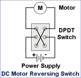
You are correct that I have the limit switches BEFORE the DPDT switch.  I may be misunderstanding what Gilly is saying but I think the limit switches cannot be AFTER the DPDT switch.  If a limit switch is placed AFTER the switch, there would be no way to apply power to the motor to go in the reverse direction.  That is, say you're going UP and the UP limit switch is reached and cut power to the motor.  You reverse the voltage polarity using the DPDT but the UP limit switch is still cutting power to the motor so there no path for the reverse voltage to drive the motor in the other direction.  Again, I may be misunderstanding Gilly's wiring so he can elaborate.

RJR implements the "DPDT" criss-cross or motor polarity reversal using 2 SPDT relays.  That is, 2 SPDT (single-pole-double-throw) relays is equivalent to a  DPDT (double-pole-double-throw).   So in essence he is using relays to perform what your DPDT switch does.  An interesting behavior of his particular wiring is it will short the motor windings in the "OFF" position.  This is referred to as dynamic braking which will instantly stop the motor from spinning.  This is usually not a problem in a geared motor (which I assume your motor is for a bridge lifter) mechanism.  But for a rapidly spinning motor, dynamically braking a motor can cause the mechanism to violently lurch; for example if you dynamically brake (short the windings) a DC geared motor in a modern engine, the engine will come to a violent stop and throw the trailing cars off the rails!  Again, for a highly geared bridge lifter motor, stopping the motor instantly (by shorting the windings) is probably not an issue.


Attachments

Images (1)
  • dpdt-on-off-on jpg
Last edited by stan2004
Big_Boy_4005 posted:

Mike, I have a whole drawer full of those switches. They don't have the little roller at the end of the arm, but you don't really need that anyway. I'll do a whole lot better than $9 a pop. Email me.

Hi Elliot, I received the switches today, Thank you so very much. Once we get past this storm I will get back to the bridge build.

Add Reply

Post

OGR Publishing, Inc., 1310 Eastside Centre Ct, Suite 6, Mountain Home, AR 72653
800-980-OGRR (6477)
www.ogaugerr.com

×
×
×
×
Link copied to your clipboard.
×
×