
Hi,

I have a Lionel JLC, GG1.  It was serviced earlier this year and a new smoke unit was installed.  The fan runs all the time now and when the smoke unit is activated, the smoke resistor turns on and the stream of smoke comes out.  The effect is the same as when the engine was new, but the fan is supposed to be off until the smoke unit is activated, then the fan comes on and blows smoke from the smoke unit since the resistor has been kept warm and ready to go.  Does anyone have a wiring diagram of how the smoke unit should be wired?

Thanks,

Lonnie

Original Post

Replies sorted oldest to newest

I tried to find a JLC GG1 so hoping this lines up to your actual product number.

https://www.lionelsupport.com/...-Stripe-4876-6-18355

The "why" is simple. The smoke unit PCB connects with a 3 wire harness. In that, one wire is for the smoke heat, and the OTHER wire is for the fan, however, SOME OF THESE tied the outer 2 pins of the input together such that fan was powered by the smoke heat power.

So, someone may have put in the WRONG STYLE and thus why the heater is heating- and so the fan is running. Again, Lionel made common smoke unit housings and thus the PCBs might fit and look very similar, but electrically they are different.

Attachments

Images (2)
  • mceclip0
  • mceclip1

I'm thinking the way this works, the AC smoke regulator was supposed to regulate a lower effective voltage/current for the resistor, and then the smoke fan might be controlled of the smoke TRIAC output of the R2LC. If an incorrect smoke unit PCB was installed, then the fan would see the power from the smoke resistor via the AC regulator, however, when the R2LC TRIAC is turned on, you are then getting that higher voltage. If they put in a new smoke unit, it also might be the 27 Ohm version, so the AC regulator is not putting enough heat/power/voltage into the resistor for full smoke, but then the smoke TRIAC of the R2LC was designed to run the 27 Ohm style anyway, so the fan is already running and this increased power then heats the resistor?

I'm just trying to tie the 2 events together- replacing the smoke unit- and then the problem kicking in. So it kinda sorta works, but does not function correctly.

Agreem the best test is a continuity test between the outer pins in the off state with the connector unplugged. That said, from the picture it looks like that is the correct smoke unit PCB and they should not be in common.

So- that does point more in the direction of programming- specific type code for the R2LC function.

https://www.lionelsupport.com/...ents/71-8354-250.pdf

According to this manual, that is type 8.

page 31

TrainMaster Command Control operations
Reprogramming your locomotive to restore features
If your locomotive is unresponsive to your commands in the TrainMaster Command Control
environment, we recommend that you follow this procedure to reset your locomotive.
1. Slide the Command reverse unit switch to the PROG position.
2. Plug in and connect your Command Base.
3. Place your locomotive on the track, then power up the track.
4. Press ENG and enter the locomotive’s ID#.
5. Press SET.
6. Press ENG and enter the locomotive’s ID# again.
7. Press AUX1.
8. Enter 8 for this particular locomotive.
8. Turn off track power and wait ten seconds.
10. Slide the Command reverse unit switch back to the RUN position.
At this point, your locomotive has been reset. Restore power to the track and operate the
locomotive as usual. Be sure to use the ID# entered in Step 4

Actually, reading the manual, without even seeing a wiring diagram, I think I get how this works.

The smoke unit resistor is powered via the AC smoke regulator.

The fan is driven from the R2LC smoke TRIAC, using a single diode and capacitor to rectify, and then a 5V regulator for the fan motor.

But here is where the magic comes in. We know that normally the smoke output of the TRIAC on the R2LC is not full wave. However, when you press and hold 9- that is often called "boost" and switches the TRIAC more on full wave. So, to exploit this, they wired the diode in such a way that the normal what we expect half wave is not charging up and thus the fan does not run. The fan does run when the 9 boost is pressed, because again, this is changing how the TRIAC fires, and that condition aligns to charging the capacitor and thus providing the regulator and fan with sufficient voltage and current to run. Releasing 9, even though to an AC meter, the TRIAC is conducting, it's more DC offset than AC and in the wrong direction to be rectified and power the fan.

Choosing the wrong or correct feature code determines how the smoke TRIAC of the R2LC behaves.

Again page 23 of the manual gives us these subtle clues.

Attachments

Images (1)
  • mceclip0

Actually, reading the manual, without even seeing a wiring diagram, I think I get how this works.

The smoke unit resistor is powered via the AC smoke regulator.

The fan is driven from the R2LC smoke TRIAC, using a single diode and capacitor to rectify, and then a 5V regulator for the fan motor.

But here is where the magic comes in. We know that normally the smoke output of the TRIAC on the R2LC is not full wave. However, when you press and hold 9- that is often called "boost" and switches the TRIAC more on full wave. So, to exploit this, they wired the diode in such a way that the normal what we expect half wave is not charging up and thus the fan does not run. The fan does run when the 9 boost is pressed, because again, this is changing how the TRIAC fires, and that condition aligns to charging the capacitor and thus providing the regulator and fan with sufficient voltage and current to run. Releasing 9, even though to an AC meter, the TRIAC is conducting, it's more DC offset than AC and in the wrong direction to be rectified and power the fan.

Choosing the wrong or correct feature code determines how the smoke TRIAC of the R2LC behaves.

Again page 23 of the manual gives us these subtle clues.

I want to know how they accomplish this trick since there is no timing element that I see in the picture.   This is on page 9 of the manual. Noting that the engine code of 8 is the standard diesel engine type, there's no timing happening that I know of with the R2LC...

Attachments

Images (1)
  • mceclip0

You probably have a point there, they could be using the motherboard and a second microprocessor on that board (update, now betting it's the railsounds board)  to perform the function.

The GG1 did have a special motherboard and we don't get to see the component backside.

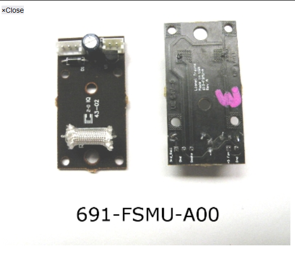
Another thought, the Railsounds 5 board appear unique with an added diode on the back????

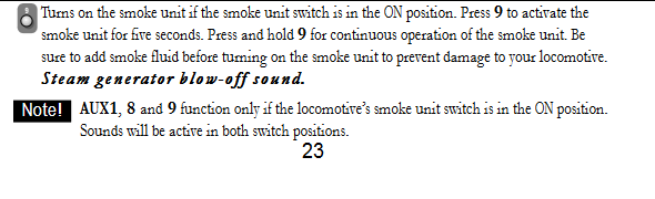
And the manual mentioning that for it to smoke in neutral, a 9V battery would be installed and that powers the railsounds board.

So does that imply the function is then off the railsounds board specific to the fan?

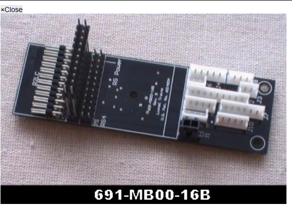
The smoke fan wiring harness clearly plugs into the motherboard on the 4 pin connector.

Again, 3 pin side goes to the smoke unit, center pin is frame ground, the other open spot in the socket is the smoke regulator wire making this blue wire the fan source.

Again, since we say this is timing based, so a microprocessor- and the Railsounds 5 did have a TRIAC onboard that can trigger and activate things. In this case, I think they used that to then fire the fan off, meanwhile the smoke resistor is heated and powered via the AC smoke regulator.

Attachments

Images (4)
  • mceclip0
  • mceclip1
  • mceclip2
  • mceclip3

Add Reply

Post
This forum is sponsored by Lionel, LLC

OGR Publishing, Inc., 1310 Eastside Centre Ct, Suite 6, Mountain Home, AR 72653
800-980-OGRR (6477)
www.ogaugerr.com

×
×
×
×
Link copied to your clipboard.
×
×