I picked up a speeder and there is no power to it when i put on track...

Does anyone know where the wiring - and + wires would go on this speeder power supply board?

The brown and black were connected to the center rail?  i am not sure where + and - wires should go...does any one have any idea?

Canadian-National-Railroad-Speeder-6-18468

thanks

Attachments

Images (1)
  • mceclip0
Original Post

Replies sorted oldest to newest

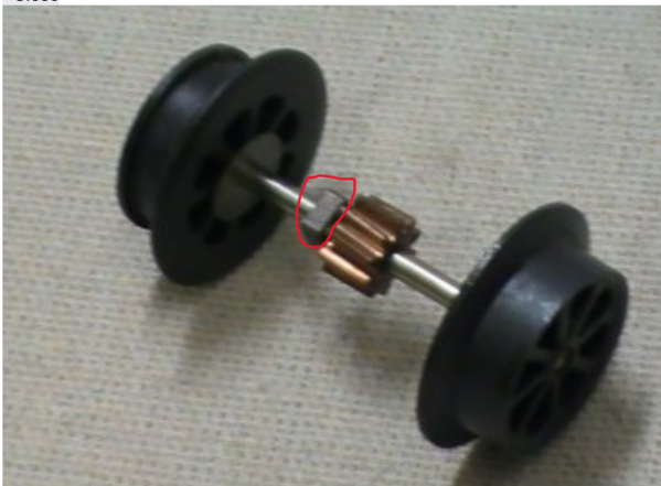
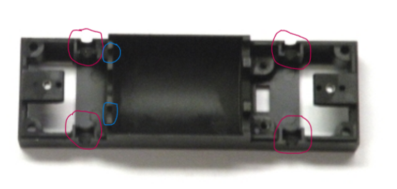
I'm very sorry to be so confused after @gunrunnerjohn gave me some great help, but I don't think the Lionel stuff is the same.  I've attached pics of the Lionel speeder body and wheel set.  There is no screw on the Lionel body that I can see like the one on the Kline.  On the car body, the wheels set in slots that are circled in red.  Those slots, and the entire body are metal.  Each wheel assembly has 2 square metal holders/bolts (?), circled in red, that fit securely into the slots in the body (note that the holder in the picture isn't in the right spot).  Those holders are not electrical conductors, they isolate the body from the outsider track rails.  When I test the continuity from the wheels to frame, I get nothing.  GRJ said to use the screws that secure the motor to the body as ground.  Those 2 holders are circled in blue, and that's what I plan to do.  I'm waiting for parts to finish this, so I can't check anything out right now.  I'll post something when I do, perhaps late next week.

I made the post in order to see what the OP, @davido1224, found out in his experience with the Lionel speeder.

I do appreciate the suggestions.


Screenshot 2024-03-22 113231
x

Attachments

Images (2)
  • x
  • Screenshot 2024-03-22 113231

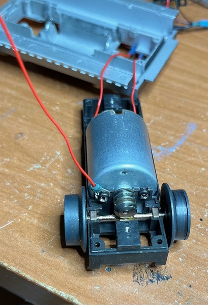
As can be guessed, @gunrunnerjohn was correct in what he told me.  The screws that hold the motor in the frame are great ground points.  While the bolt-type things that hold the wheel assembly into the frame isolate the body from the outside rail, the worm gear on the wheel axle contacts the motor worm gear and provides a pathway.  I soldered an eyelet onto some wire, screwed it into the motor mount, and verified that that connection does go to ground.  I suspect that when I did my previous post, that was without the motor being mounted into the frame.  Once that's done the entire frame should be able to be a ground contact.

I'm still waiting on some parts to finish this, so more in a few days.

IMG_5287

Attachments

Images (1)
  • IMG_5287

Add Reply

Post
This forum is sponsored by Lionel, LLC

OGR Publishing, Inc., 1310 Eastside Centre Ct, Suite 6, Mountain Home, AR 72653
800-980-OGRR (6477)
www.ogaugerr.com

×
×
×
×
Link copied to your clipboard.
×
×