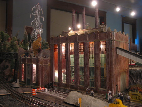
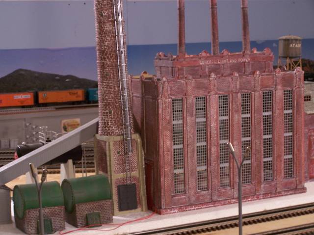
Just completed my Korber General Power & Light kit and would like to add transformers and whatever else would complement that kit.
Any picture would be helpful as well!
Thanks in advance,
Cesar
Original Post


|
|
Replies sorted oldest to newest
quote:Well it didn't work I'll try again later
 /Users/richardseaney/Pictures/iPhoto Library/Originals/2007/my_pix/0807070907.jpg
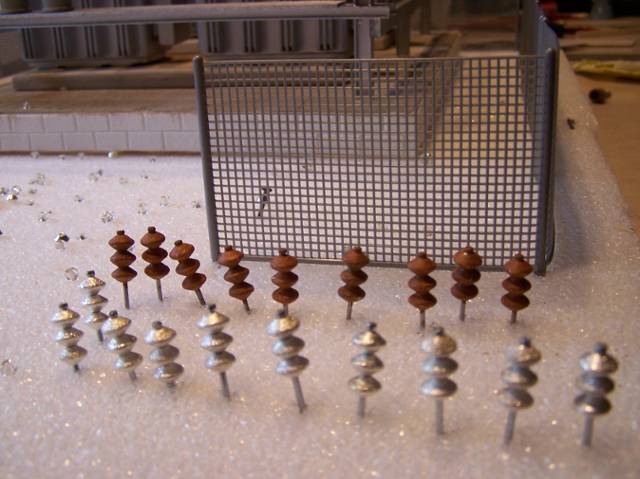
quote:C'mon, Cesar, You can easily make some, using pill containers, styrene and the threaded ends of drywall screws.
quote:The insulators should be brown or battleship gray (Gloss) leave the tip silver to simulate metal
quote:Originally posted by FatBoy:quote:C'mon, Cesar, You can easily make some, using pill containers, styrene and the threaded ends of drywall screws.
Dave, I actually have all these item and some but not sure how it all comes together i.e. where cables\wire go from and to. Kind of how a substation is configured. Tried doing some searches but cannot find what I'm really looking for. Thanks for the comments.quote:The insulators should be brown or battleship gray (Gloss) leave the tip silver to simulate metal
Thanks for the info, David. These are the things that I am not aware of as far as detailing.
Any prototype photos would be helpful as well.
Cesar
quote:Just google power substations i'm sure you'll get plenty of pics .If you going with modern era stuff they're gray and 1950's and before brown
quote:Cesar,
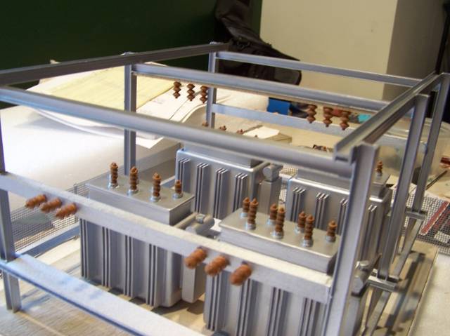
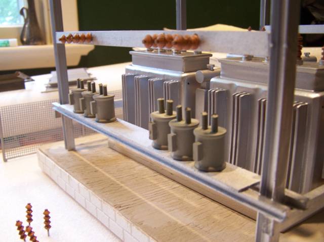
That first pic in the first row is a good example of the insulators
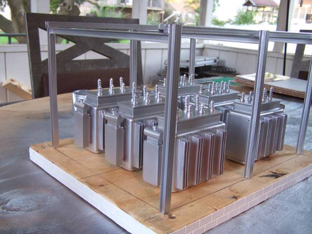
The steel frame work is a Buss.This allows them to branch off different lines in various directions .the buss work also has disconnects so they can turn off a particular circuit without interruption to the others.In other words one transformer would feed 3 or 4 -3 phase circuits a 3 phase circuit is Cross arm on top 3 wires on top one wire below those.
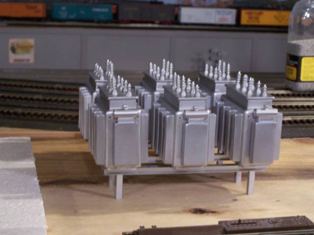
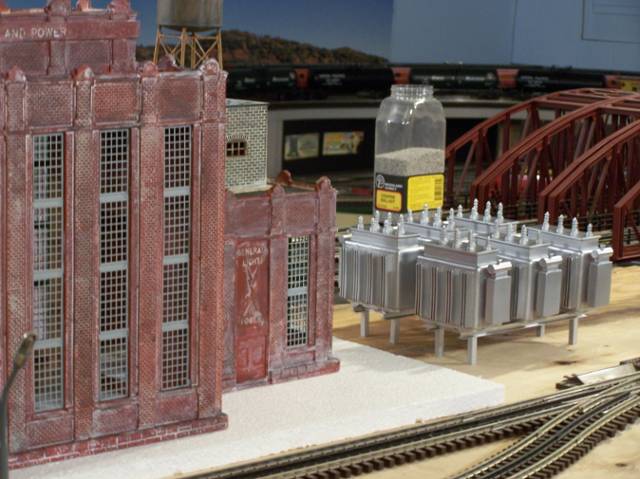
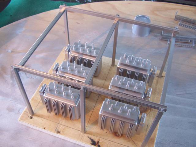
quote:You have 3 wires going in the XFMR and 4 coming out .The 3 taller Bushings or insulators are off the buss work and the 3 smaller are for the wires going out to the poles with one of the 4 being a ground(Simulate a ground rod driven in the earth.
quote:XFMR's are very heavy(We're talking about in Tons) It's not uncommon for a substation XFMR to weigh 30 or 40 tons so I think you should close in your rack and try to make it look more like concrete since in total weight you'd have several hundred thousand pounds there although you got them raised and that's the way they are in the real world for flooding and to keep them out of arms reach
quote:Originally posted by VaGolfer1950:
http://token3rail.blogspot.com...tric-substation.html
quote:Originally posted by DPC:
close but no We"o"
quote:Originally posted by Avanti:quote:Originally posted by DPC:
close but no We"o"
I've GOT to be the only one on the list who understands the above reference.
quote:http://token3rail.blogspot.com...tric-substation.html
quote:I'll take my camera to work and get some good photos with detail for you to work with. I'll try to have them posted tomorrow after I get home.
quote:Originally posted by FatBoy:
Chip,
Thanks for taking the time in providing those pictures, they are very helpful. I have a much better idea of how it will be layed out.
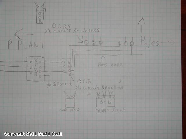
David,
Thanks for the sketch, it's all starting to make sense now. The only question I have is: Does each OCR support 1 buss coming off the OCB? I see you have it illustrated that there are 3 OCR's coming off the OCB. Just wanted to confirm.
Thanks for everyones input, gonna start on this project today. Pictures to follow....
Cesar
quote:Originally posted by FatBoy:
Thanks David for all your efforts and information.
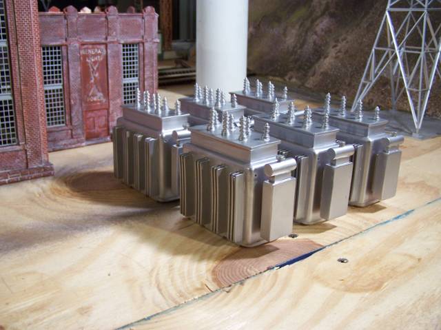
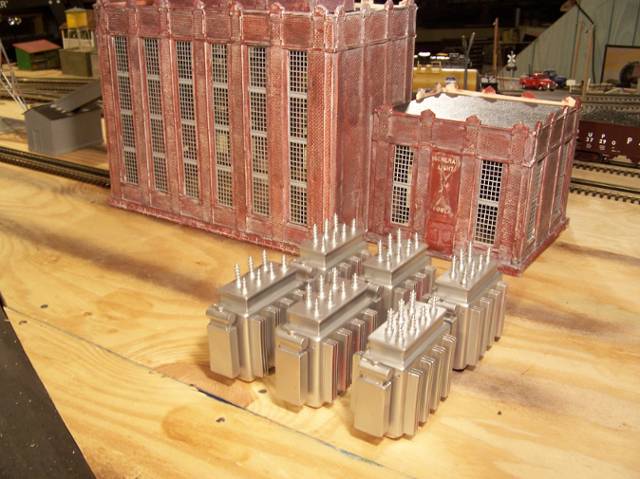
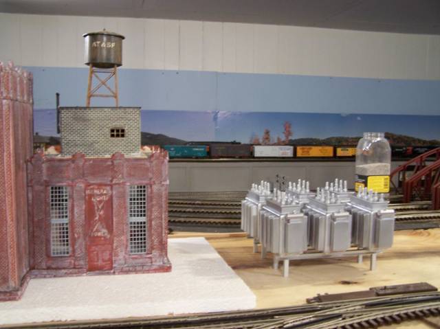
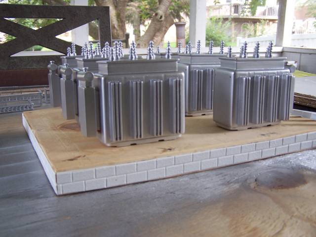
I began my project today and this is what i have so far.
I made a cinder block base for the transformers.(not painted yet)
Cesar


Access to this requires an OGR Forum Supporting Membership
