I have learned that my Marx accessories will not work from track power without drastic slowdown of the train. I have adequate power from the transformer accessory side. Can accessories powered from accessory side of transformer be activated automatically by the train?
Replies sorted oldest to newest
I'd say the 3 most common methods are:
1) Pressure plate - where the weight of the train presses together 2 metal contacts to effect an electrical switch
2) Isolated outer-rail - where the metal axles of the passing train electrically connects the two outer rails to effect an electrical switch
3) Infrared detector - where an invisible (infrared) light beam is aimed across the track and the passing train reflects the beam. The reflection triggers an electrical relay which becomes the electrical switch
Method 2) is probably the most common but can be impractical to implement - especially after the fact if, for example, you have to pull-up meticulously ballasted track. If you tell us what kind of track you have, there may be off-the-shelf solutions.
Thank you, Stan2004. Very simple layout: Marx track is on felt fastened to plywood. I know how to make an isolated rail. Will that method work if the accessory I need to activate is connected to the accessory side of the transformer? I sure appreciate your help. Ray
What transformer do you have?
The idea is the accessory "hot" goes direct to accessory and the isolated rail provides the common connection when wheels are on the section. Many but not all transformers internally connect the track power common to accessory common for you...hence question about transformer.
Oh my! Thank you, STAN2004. I have two Marx transformers. One reads catalogue 1669, 100 watts, to acces 15 volts. The other reads catalogue 1249, 50 watts and to acces 13 volts. There is no indication of hot or ground. I really appreciate your help. Ray
BabyRay posted:I have learned that my Marx accessories will not work from track power without drastic slowdown of the train. I have adequate power from the transformer accessory side. Can accessories powered from accessory side of transformer be activated automatically by the train?
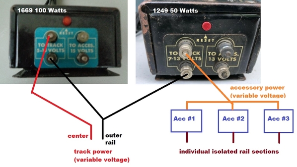
If you have 2 transformers, why not use one for train power and the other for accessory power. The idea is to isolate/insulate the goings-on of the train with the goings-on of the accessories.
For all train transformers I'm aware of that have both track and accessory outputs, when they say 100 Watts, or 50 Watts, or whatever Watts, that is the total combined power. If you dedicate the 1669 to provide JUST train power, then the 1249 can power JUST accessories. This means changing the speed of the train (using the 1669) will not affect the voltage going to the accessories. Additionally, if you use the variable (track) output of the 1249 so you can fine-tune the accessory performance (brightness, vibration, whatever).
The "trick" is to tie together one side of each transformer to the outer-rail as illustrated above with the black connection. Then, when a wheel axle(s) passes over the isolated rail, it closes the circuit and the corresponding accessory receives power from the 1249.
I just cut-paste the above photos from the web; I did not readily find the internal wiring diagrams for these transformers to see if/how these transformers share terminals. But when you say you have 2 transformers, this becomes moot. Since the 2 transformer outputs are isolated from each other, you can define "common" side shown as the lower terminal in this case.
Attachments
Stan. thank you so much for taking a lot of time helping me. I am anxious to utilize your suggestions. Appreciate your time and expertise. Best. Ray


