
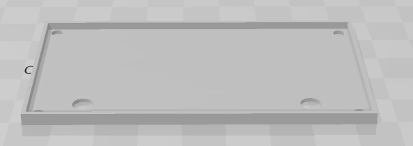
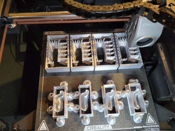
I thought this was an interesting look inside all the supports required to print these two piece trackside cabinets for the ultrasonic sensor boards.  About 25% of the material I used for the printing is used for supports!

Attachments

Images (2)
  • mceclip0
  • mceclip1
Original Post

Replies sorted oldest to newest

Well, this is Rod Stewart's design, I just did a few tweaks on it.  I have the ultrasonic boards so I though I'd make some cabinets.  I'm printing them with silver silk, it really looks like metal.

I'm creating a base to locate them now.  You screw this down, set the PCB on it, and feed the wires through the two holes.  That way the cabinet isn't going to wander around and you can lift it off to get to the innards.

Attachments

Images (1)
  • mceclip0
Last edited by Rich Melvin
@Rod Stewart posted:

Nice work John; they are looking good!

Thanks,

I decided that it would be handy to have a base under these so they have a place to be positioned.  I attached the 3D file to this post.  It has 3mm holes for mounting to the platform and larger holes for the wires at each end of the board.

Untrasonic Enclosure sub-base

Trackside Cabinet Mounting Base.stl

Attachments

@Rod Stewart posted:

That base looks good John. Just curious about the inside dimensions? If you are using your final R1.4 pcb design they should fit fine of course, being only 38 x 51 mm (1.5 x 2"). The boards I have used exclusively so far are my own layout; 76 x 43 mm. Just wondering if they will fit inside the raised perimeter of that base?

The older boards may not fit, but I only have the later R1.4 boards here, so they'll work fine.  I ordered a big batch of the R1.4 boards from JLCPCB, so I built for that form-factor.

The internal size inside the rim is 42mm x 77mm, so your boards wouldn't quite fit inside the rim.

It was suggested that the base cabinet should really be concrete, so I printed a couple in gray, I think they may be a better match.  Here's a contrast...

Not totally happy with the lines, but it was cheap filament that I don't think likes the speed I'm printing at, even though I slowed it down to half speed.

Ultrasonic Sensor Trackside Cabinets

I like the concrete look; mind you I may be kind of partial! And the lines look fine when you realize that concrete in the real world is rarely perfectly smooth, just saying.......

@Darrell posted:

You can try adjusting the plate temperature,  or print with a brim to help adhesion.

I can't imagine a brim would help, the supports cover a broad base.  If that ain't gonna' stick, I doubt a few more lines of filament would havechanged it.  I never had this problem printing with the Creality Hyper-PLA, it's this cheap filament that is different.  Live and learn, don't buy cheap filament.

Attachments

Images (1)
  • mceclip0

That print definitely had enough surface area touching the build plate and should not have moved.

Until very recently FDM printers were printing anywhere from 50-150mm/s.  John's printer can do 600mm/s (it can probably do 800mm/s).  At half speed... 300mm/s it's 2-6 times faster than most FDM printers.  Not all filament producers have formulated their filaments to handle these new printing speeds.  If you get one of these new 'speedy' printers be aware that not all of the filaments on the market can meet these new printing standards.

Last edited by Dennis-LaRock

Add Reply

Post

OGR Publishing, Inc., 1310 Eastside Centre Ct, Suite 6, Mountain Home, AR 72653
800-980-OGRR (6477)
www.ogaugerr.com

×
×
×
×
Link copied to your clipboard.
×
×